2005 NISSAN NAVARA ignition
[x] Cancel search: ignitionPage 1324 of 3171
EC-344
PNP SWITCH
Diagnostic Procedure
EBS01KMV
A/T MODELS
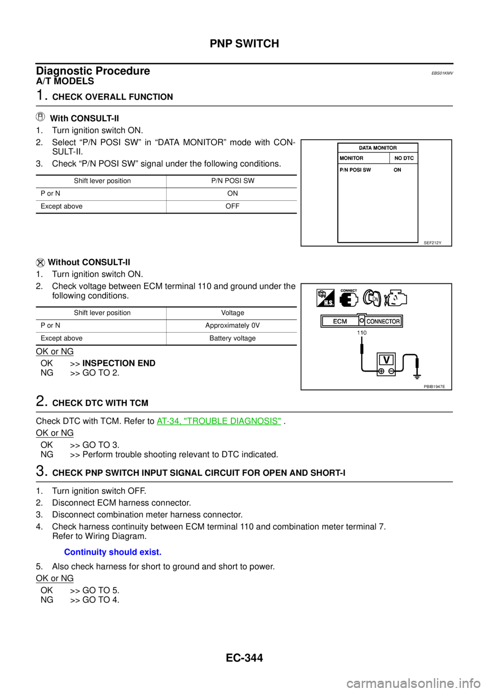
1.CHECK OVERALL FUNCTION
With CONSULT-II
1. Turn ignition switch ON.
2. Select “P/N POSI SW” in “DATA MONITOR” mode with CON-
SULT-II.
3. Check “P/N POSI SW” signal under the following conditions.
Without CONSULT-II
1. Turn ignition switch ON.
2. Check voltage between ECM terminal 110 and ground under the
following conditions.
OK or NG
OK >>INSPECTION END
NG >> GO TO 2.
2.CHECK DTC WITH TCM
Check DTC with TCM. Refer toAT-34, "
TROUBLE DIAGNOSIS".
OK or NG
OK >> GO TO 3.
NG >> Perform trouble shooting relevant to DTC indicated.
3.CHECK PNP SWITCH INPUT SIGNAL CIRCUIT FOR OPEN AND SHORT-I
1. Turn ignition switch OFF.
2. Disconnect ECM harness connector.
3. Disconnect combination meter harness connector.
4. Check harness continuity between ECM terminal 110 and combination meter terminal 7.
Refer to Wiring Diagram.
5. Also check harness for short to ground and short to power.
OK or NG
OK >> GO TO 5.
NG >> GO TO 4.
Shift lever position P/N POSI SW
PorN ON
Except above OFF
SEF212Y
Shift lever position Voltage
P or N Approximately 0V
Except above Battery voltage
PBIB1947E
Continuity should exist.
Page 1326 of 3171
EC-346
PNP SWITCH
M/T MODELS
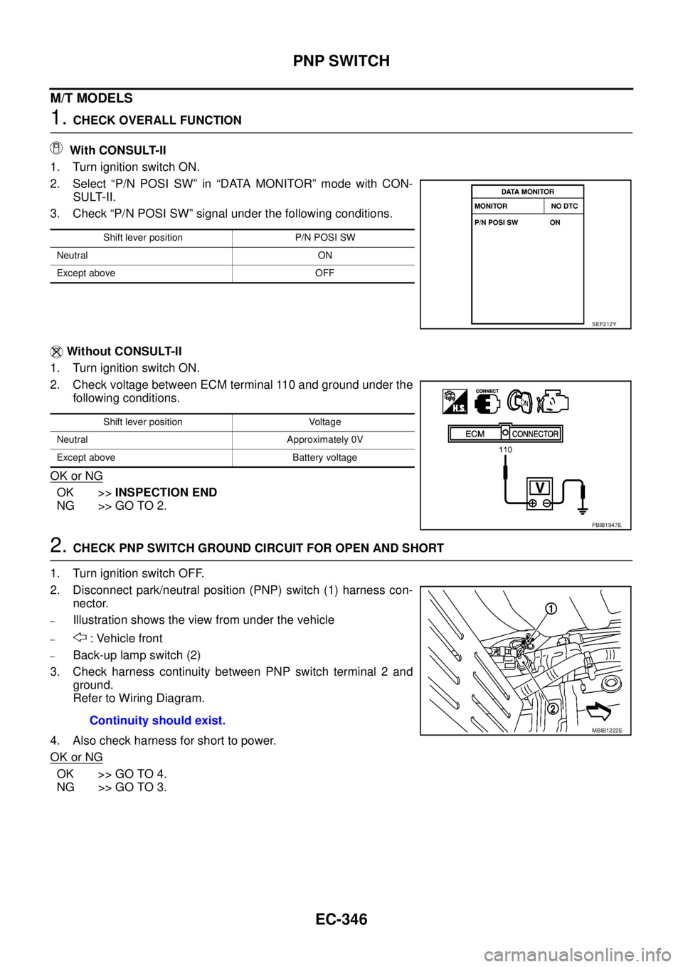
1.CHECK OVERALL FUNCTION
With CONSULT-II
1. Turn ignition switch ON.
2. Select “P/N POSI SW” in “DATA MONITOR” mode with CON-
SULT-II.
3. Check “P/N POSI SW” signal under the following conditions.
Without CONSULT-II
1. Turn ignition switch ON.
2. Check voltage between ECM terminal 110 and ground under the
following conditions.
OK or NG
OK >>INSPECTION END
NG >> GO TO 2.
2.CHECK PNP SWITCH GROUND CIRCUIT FOR OPEN AND SHORT
1. Turn ignition switch OFF.
2. Disconnect park/neutral position (PNP) switch (1) harness con-
nector.
–Illustration shows the view from under the vehicle
–: Vehicle front
–Back-up lamp switch (2)
3. Check harness continuity between PNP switch terminal 2 and
ground.
Refer to Wiring Diagram.
4. Also check harness for short to power.
OK or NG
OK >> GO TO 4.
NG >> GO TO 3.
Shift lever position P/N POSI SW
Neutral ON
Except above OFF
SEF212Y
Shift lever position Voltage
Neutral Approximately 0V
Except above Battery voltage
PBIB1947E
Continuity should exist.MBIB1222E
Page 1329 of 3171
START SIGNAL
EC-349
C
D
E
F
G
H
I
J
K
L
MA
EC
Diagnostic ProcedureEBS01KMX
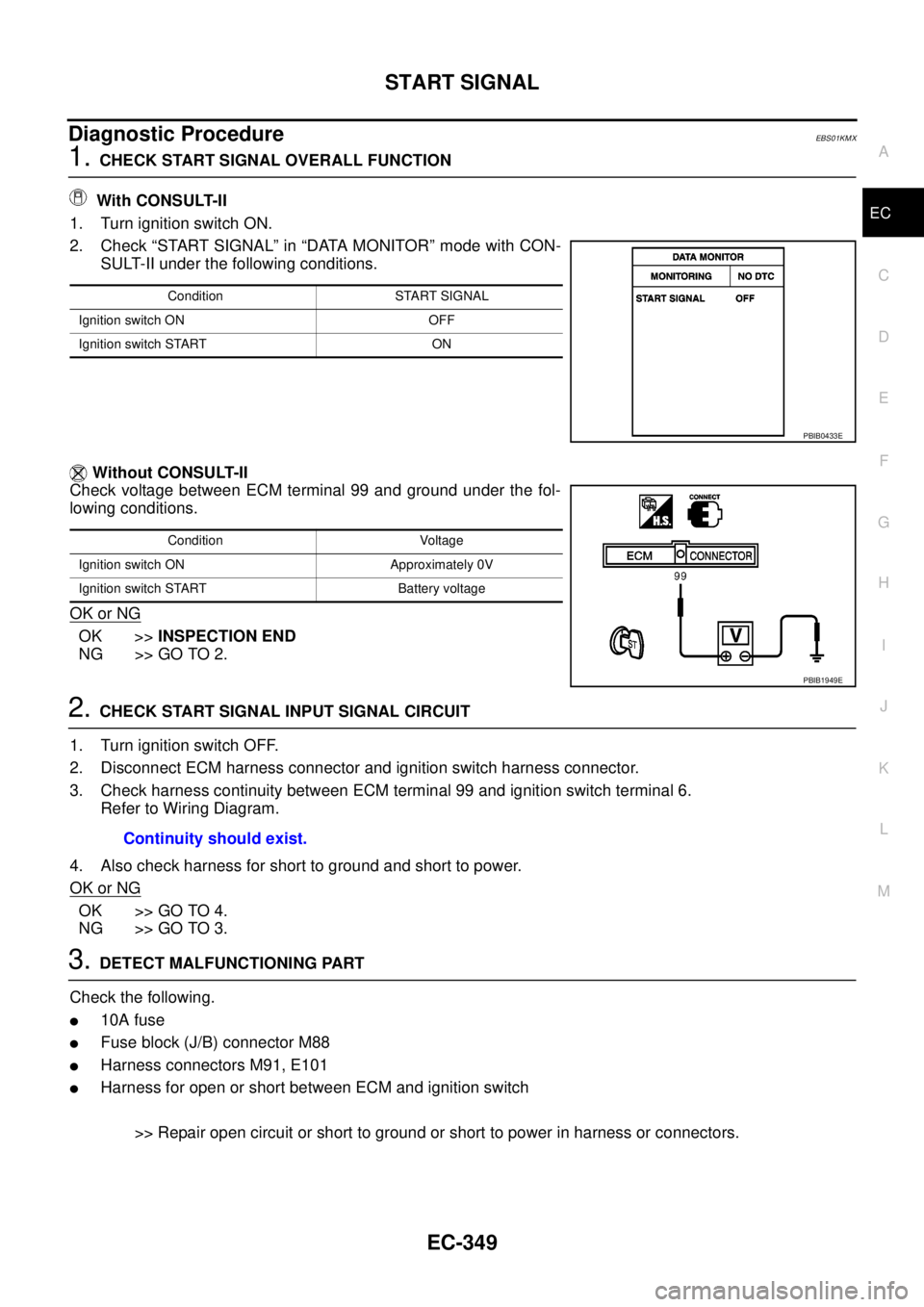
1.CHECK START SIGNAL OVERALL FUNCTION
With CONSULT-II
1. Turn ignition switch ON.
2. Check “START SIGNAL” in “DATA MONITOR” mode with CON-
SULT-II under the following conditions.
Without CONSULT-II
Check voltage between ECM terminal 99 and ground under the fol-
lowing conditions.
OK or NG
OK >>INSPECTION END
NG >> GO TO 2.
2.CHECK START SIGNAL INPUT SIGNAL CIRCUIT
1. Turn ignition switch OFF.
2. Disconnect ECM harness connector and ignition switch harness connector.
3. Check harness continuity between ECM terminal 99 and ignition switch terminal 6.
Refer to Wiring Diagram.
4. Also check harness for short to ground and short to power.
OK or NG
OK >> GO TO 4.
NG >> GO TO 3.
3.DETECT MALFUNCTIONING PART
Check the following.
l10A fuse
lFuse block (J/B) connector M88
lHarness connectors M91, E101
lHarness for open or short between ECM and ignition switch
>> Repair open circuit or short to ground or short to power in harness or connectors.
Condition START SIGNAL
Ignition switch ON OFF
Ignition switch START ON
PBIB0433E
Condition Voltage
Ignition switch ON Approximately 0V
Ignition switch START Battery voltage
PBIB1949E
Continuity should exist.
Page 1333 of 3171
ASCD INDICATOR
EC-353
C
D
E
F
G
H
I
J
K
L
MA
EC
Diagnostic ProcedureEBS01KN0
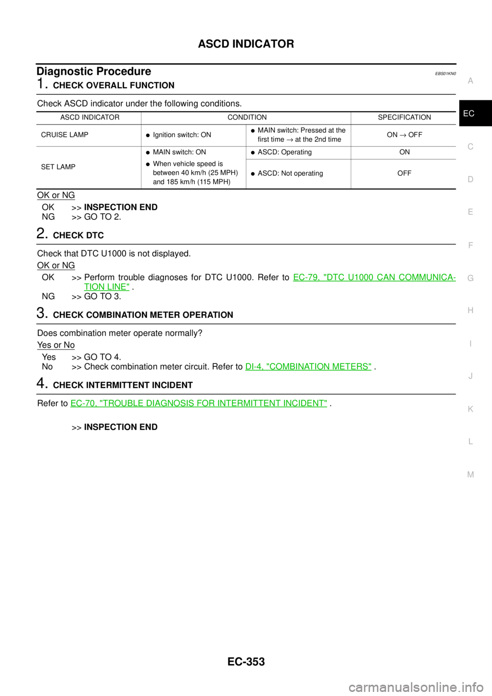
1.CHECK OVERALL FUNCTION
Check ASCD indicator under the following conditions.
OK or NG
OK >>INSPECTION END
NG >> GO TO 2.
2.CHECK DTC
Check that DTC U1000 is not displayed.
OK or NG
OK >> Perform trouble diagnoses for DTC U1000. Refer toEC-79, "DTC U1000 CAN COMMUNICA-
TION LINE".
NG >> GO TO 3.
3.CHECK COMBINATION METER OPERATION
Does combination meter operate normally?
Ye s o r N o
Ye s > > G O T O 4 .
No >> Check combination meter circuit. Refer toDI-4, "
COMBINATION METERS".
4.CHECK INTERMITTENT INCIDENT
Refer toEC-70, "
TROUBLE DIAGNOSIS FOR INTERMITTENT INCIDENT".
>>INSPECTION END
ASCD INDICATOR CONDITION SPECIFICATION
CRUISE LAMP
lIgnition switch: ONlMAIN switch: Pressed at the
first time®at the 2nd timeON®OFF
SET LAMP
lMAIN switch: ON
lWhen vehicle speed is
between 40 km/h (25 MPH)
and185km/h(115MPH)
lASCD: Operating ON
lASCD: Not operating OFF
Page 1337 of 3171
SERVICE DATA AND SPECIFICATIONS (SDS)
EC-357
C
D
E
F
G
H
I
J
K
L
MA
EC
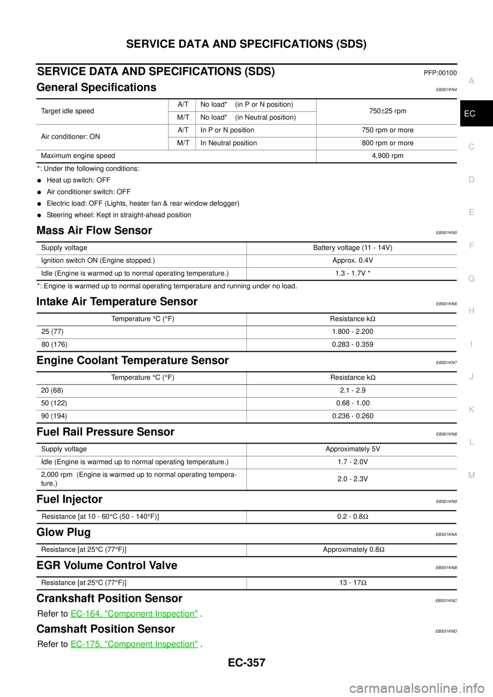
SERVICE DATA AND SPECIFICATIONS (SDS)PFP:00100
General SpecificationsEBS01KN4
*: Under the following conditions:
lHeat up switch: OFF
lAir conditioner switch: OFF
lElectric load: OFF (Lights, heater fan & rear window defogger)
lSteering wheel: Kept in straight-ahead position
Mass Air Flow SensorEBS01KN5
*: Engine is warmed up to normal operating temperature and running under no load.
Intake Air Temperature SensorEBS01KN6
Engine Coolant Temperature SensorEBS01KN7
Fuel Rail Pressure SensorEBS01KN8
Fuel InjectorEBS01KN9
Glow PlugEBS01KNA
EGR Volume Control ValveEBS01KNB
Crankshaft Position SensorEBS01KNC
Refer toEC-164, "Component Inspection".
Camshaft Position SensorEBS01KND
Refer toEC-175, "Component Inspection".
Target idle speedA/T No load* (in P or N position)
750±25 rpm
M/T No load* (in Neutral position)
Air conditioner: ONA/T In P or N position 750 rpm or more
M/T In Neutral position 800 rpm or more
Maximum engine speed4,900 rpm
Supply voltageBattery voltage (11 - 14V)
Ignition switch ON (Engine stopped.) Approx. 0.4V
Idle (Engine is warmed up to normal operating temperature.) 1.3 - 1.7V *
Temperature°C(°F) Resistance kW
25 (77)1.800 - 2.200
80 (176)0.283 - 0.359
Temperature°C(°F) Resistance kW
20 (68)2.1 - 2.9
50 (122)0.68 - 1.00
90 (194)0.236 - 0.260
Supply voltageApproximately 5V
Idle (Engine is warmed up to normal operating temperature.) 1.7 - 2.0V
2,000 rpm (Engine is warmed up to normal operating tempera-
ture.)2.0 - 2.3V
Resistance [at 10 - 60°C (50 - 140°F)] 0.2 - 0.8W
Resistance [at 25°C(77°F)] Approximately 0.8W
Resistance [at 25°C(77°F)] 13 - 17W
Page 1341 of 3171
PRECAUTIONS
EI-3
C
D
E
F
G
H
J
K
L
MA
B
EI
PRECAUTIONSPFP:00001
Service NoticeEIS00DY1
lWhen removing or installing various parts, place a cloth or padding on the vehicle body to prevent
scratches.
lHandle trim, molding, instruments, grille, etc. carefully during removing or installing. Be careful not to soil
or damage them.
lApply sealing compound where necessary when installing parts.
lWhen applying sealing compound, be careful that the sealing compound does not protrude from parts.
lWhen replacing any metal parts (for example body outer panel, members, etc.), be sure to take rust pre-
vention measures.
Precautions for Supplemental Restraint System (SRS) “AIR BAG” and “SEAT
BELT PRE-TENSIONER”
EIS00DZ5
The Supplemental Restraint System such as “AIR BAG” and “SEAT BELT PRE-TENSIONER”, used along
with a front seat belt, helps to reduce the risk or severity of injury to the driver and front passenger for certain
types of collision. Information necessary to service the system safely is included in the SRS and SB section of
this Service Manual.
WARNING:
lTo avoid rendering the SRS inoperative, which could increase the risk of personal injury or death
in the event of a collision which would result in air bag inflation, all maintenance must be per-
formed by an authorized NISSAN/INFINITI dealer.
lImproper maintenance, including incorrect removal and installation of the SRS, can lead to per-
sonal injury caused by unintentional activation of the system. For removal of Spiral Cable and Air
Bag Module, see the SRS section.
lDo not use electrical test equipment on any circuit related to the SRS unless instructed to in this
Service Manual. SRS wiring harnesses can be identified by yellow and/or orange harnesses or
harness connectors.
Precautions for SRS “AIR BAG” and “SEAT BELT PRE-TENSIONER” ServiceEIS00DZ2
lDo not use electrical test equipment to check SRS circuits unless instructed to in this Service Manual.
lBefore servicing the SRS, turn ignition switch OFF, disconnect both battery cables and wait at least 3 min-
utes.
For approximately 3 minutes after the cables are removed, it is still possible for the air bag and seat belt
pre-tensioner to deploy. Therefore, do not work on any SRS connectors or wires until at least 3 minutes
have passed.
lThe air bag diagnosis sensor unit must always be installed with the arrow marks “Ü” pointing toward the
front of the vehicle for proper operation. Also check the air bag diagnosis sensor unit for cracks, deformi-
ties or rust before installation and replace as required.
lThe spiral cable must be aligned with the neutral position since its rotations are limited. Do not attempt to
turn steering wheel or column after removal of steering gear.
lHandle air bag module carefully. Always place driver and front passenger air bag modules with the pad
side facing upward and seat mounted front side air bag module standing with the stud bolt side facing
down.
lConduct self-diagnosis to check entire SRS for proper function after replacing any components.
lAfter air bag inflates, the front instrument panel assembly should be replaced if damaged.
Page 1447 of 3171
CAMSHAFT
EM-65
C
D
E
F
G
H
I
J
K
L
MA
EM
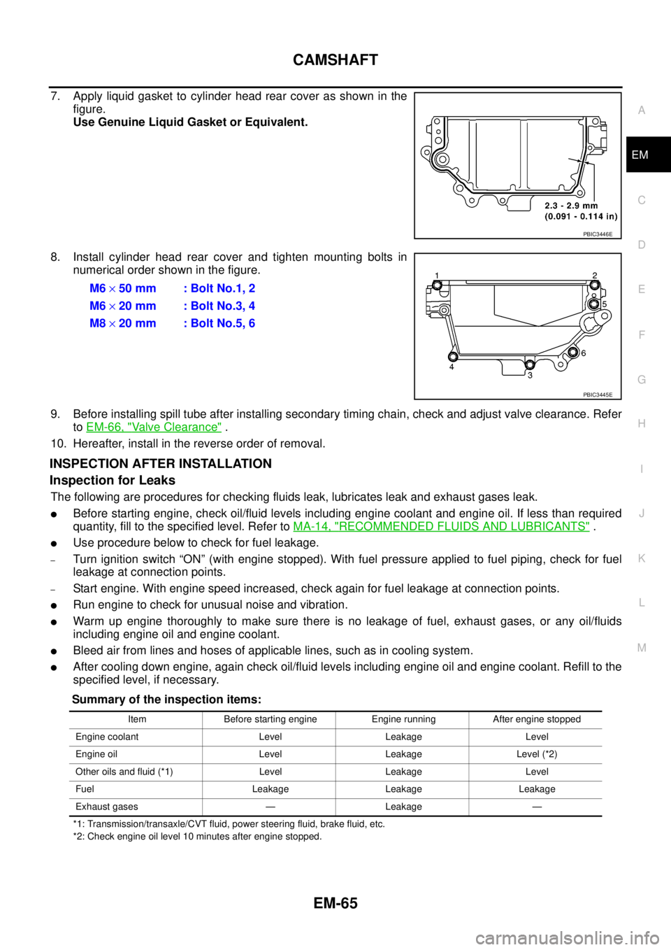
7. Apply liquid gasket to cylinder head rear cover as shown in the
figure.
Use Genuine Liquid Gasket or Equivalent.
8. Install cylinder head rear cover and tighten mounting bolts in
numerical order shown in the figure.
9. Before installing spill tube after installing secondary timing chain, check and adjust valve clearance. Refer
toEM-66, "
Valve Clearance".
10. Hereafter, install in the reverse order of removal.
INSPECTION AFTER INSTALLATION
Inspection for Leaks
The following are procedures for checking fluids leak, lubricates leak and exhaust gases leak.
lBefore starting engine, check oil/fluid levels including engine coolant and engine oil. If less than required
quantity, fill to the specified level. Refer toMA-14, "
RECOMMENDED FLUIDS AND LUBRICANTS".
lUse procedure below to check for fuel leakage.
–Turn ignition switch “ON” (with engine stopped). With fuel pressure applied to fuel piping, check for fuel
leakage at connection points.
–Start engine. With engine speed increased, check again for fuel leakage at connection points.
lRun engine to check for unusual noise and vibration.
lWarm up engine thoroughly to make sure there is no leakage of fuel, exhaust gases, or any oil/fluids
including engine oil and engine coolant.
lBleed air from lines and hoses of applicable lines, such as in cooling system.
lAfter cooling down engine, again check oil/fluid levels including engine oil and engine coolant. Refill to the
specified level, if necessary.
Summary of the inspection items:
*1: Transmission/transaxle/CVT fluid, power steering fluid, brake fluid, etc.
*2: Check engine oil level 10 minutes after engine stopped.
PBIC3446E
M6´50 mm : Bolt No.1, 2
M6´20 mm : Bolt No.3, 4
M8´20 mm : Bolt No.5, 6
PBIC3445E
Item Before starting engine Engine running After engine stopped
Engine coolant Level Leakage Level
Engine oil Level Leakage Level (*2)
Other oils and fluid (*1) Level Leakage Level
Fuel Leakage Leakage Leakage
Exhaust gases — Leakage —
Page 1459 of 3171
SECONDARY TIMING CHAIN
EM-77
C
D
E
F
G
H
I
J
K
L
MA
EM
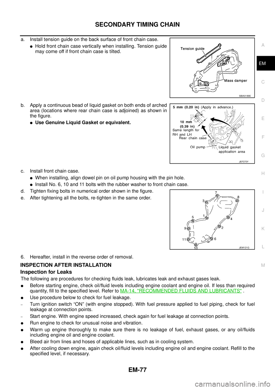
a. Install tension guide on the back surface of front chain case.
lHold front chain case vertically when installing. Tension guide
may come off if front chain case is tilted.
b. Apply a continuous bead of liquid gasket on both ends of arched
area (locations where rear chain case is adjoined) as shown in
the figure.
lUse Genuine Liquid Gasket or equivalent.
c. Install front chain case.
lWhen installing, align dowel pin on oil pump housing with the pin hole.
lInstall No. 6, 10 and 11 bolts with the rubber washer to front chain case.
d. Tighten fixing bolts in numerical order shown in the figure.
e. After tightening all the bolts, re-tighten in the same order.
6. Hereafter, install in the reverse order of removal.
INSPECTION AFTER INSTALLATION
Inspection for Leaks
The following are procedures for checking fluids leak, lubricates leak and exhaust gases leak.
lBefore starting engine, check oil/fluid levels including engine coolant and engine oil. If less than required
quantity, fill to the specified level. Refer toMA-14, "
RECOMMENDED FLUIDS AND LUBRICANTS".
lUse procedure below to check for fuel leakage.
–Turn ignition switch “ON” (with engine stopped). With fuel pressure applied to fuel piping, check for fuel
leakage at connection points.
–Start engine. With engine speed increased, check again for fuel leakage at connection points.
lRun engine to check for unusual noise and vibration.
lWarm up engine thoroughly to make sure there is no leakage of fuel, exhaust gases, or any oil/fluids
including engine oil and engine coolant.
lBleed air from lines and hoses of applicable lines, such as in cooling system.
lAfter cooling down engine, again check oil/fluid levels including engine oil and engine coolant. Refill to the
specified level, if necessary.
SBIA0189E
JEF370Y
JEM121G