2005 NISSAN NAVARA ignition
[x] Cancel search: ignitionPage 1633 of 3171
HOW TO USE THIS MANUAL
GI-11
C
D
E
F
G
H
I
J
K
L
MB
GI
How to Follow Trouble DiagnosesEAS001GX
DESCRIPTION
NOTICE:
Trouble diagnoses indicate work procedures required to diagnose problems effectively. Observe the following
instructions before diagnosing.
1.Before performing trouble diagnoses, read the “Preliminary Check”, the “Symptom Chart” or the
“Work Flow”.
2.After repairs, re-check that the problem has been completely eliminated.
3.Refer to Component Parts and Harness Connector Location for the Systems described in each
section for identification/location of components and harness connectors.
4.Refer to the Circuit Diagram for quick pinpoint check.
If you need to check circuit continuity between harness connectors in more detail, such as when a
sub-harness is used, refer to Wiring Diagram in each individual section and Harness Layout in PG
section for identification of harness connectors.
5.When checking circuit continuity, ignition switch should be OFF.
6.Before checking voltage at connectors, check battery voltage.
7.After accomplishing the Diagnostic Procedures and Electrical Components Inspection, make sure
that all harness connectors are reconnected as they were.
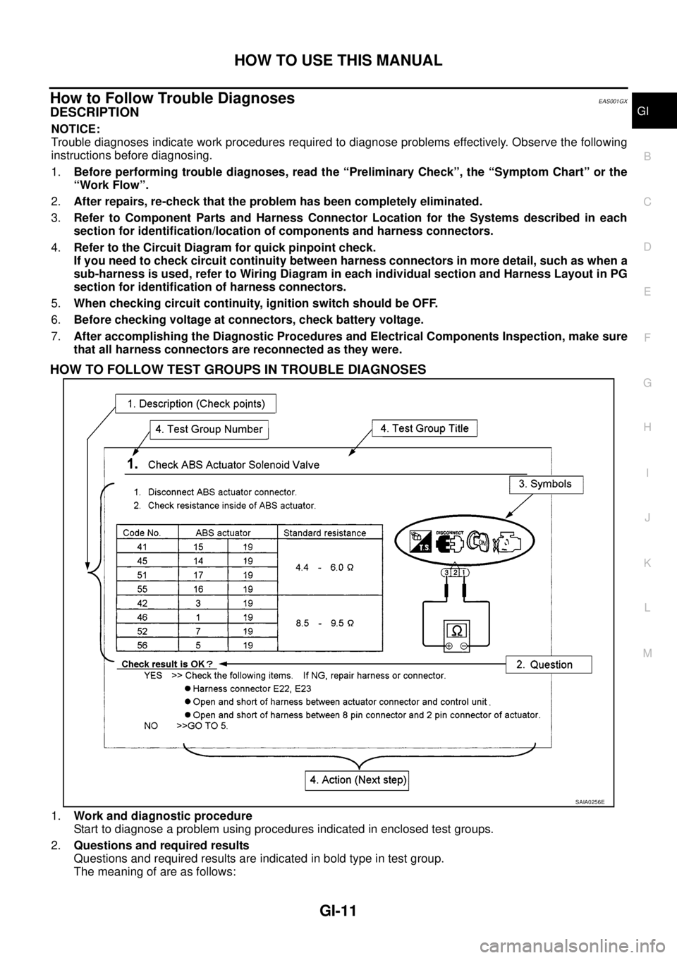
HOW TO FOLLOW TEST GROUPS IN TROUBLE DIAGNOSES
1.Work and diagnostic procedure
Start to diagnose a problem using procedures indicated in enclosed test groups.
2.Questions and required results
Questions and required results are indicated in bold type in test group.
The meaning of are as follows:
SAIA0256E
Page 1641 of 3171
HOW TO USE THIS MANUAL
GI-19
C
D
E
F
G
H
I
J
K
L
MB
GI
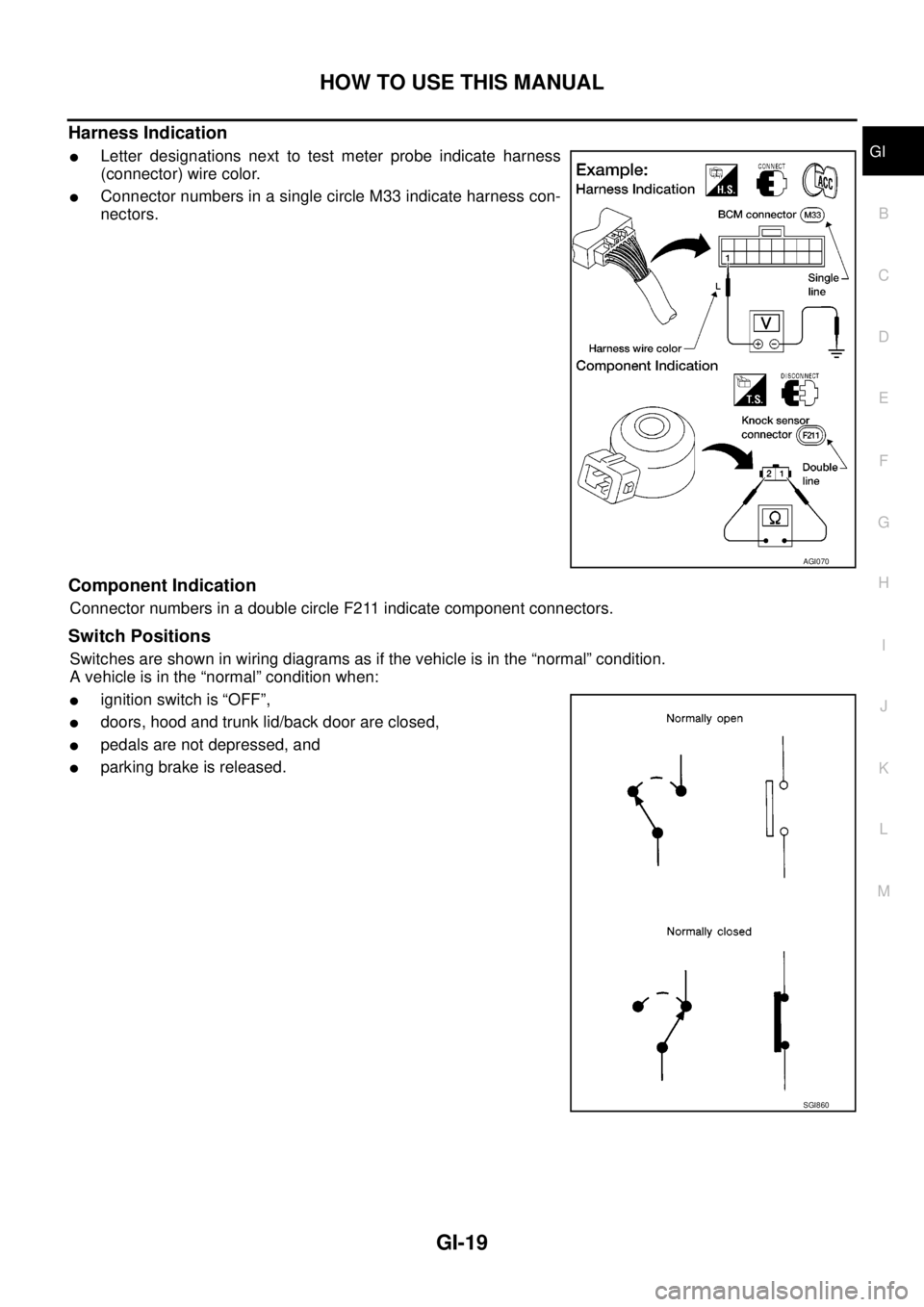
Harness Indication
lLetter designations next to test meter probe indicate harness
(connector) wire color.
lConnector numbers in a single circle M33 indicate harness con-
nectors.
Component Indication
Connector numbers in a double circle F211 indicate component connectors.
Switch Positions
Switches are shown in wiring diagrams as if the vehicle is in the “normal” condition.
A vehicle is in the “normal” condition when:
lignition switch is “OFF”,
ldoors, hood and trunk lid/back door are closed,
lpedals are not depressed, and
lparking brake is released.
AGI070
SGI860
Page 1650 of 3171
GI-28
SERVICE INFORMATION FOR ELECTRICAL INCIDENT
VOLTAGE CHECK METHOD
To help in understanding the diagnosis of open circuits please refer to the previous schematic.
In any powered circuit, an open can be found by methodically checking the system for the presence of voltage.
This is done by switching the DMM to the voltage function.
lConnect one probe of the DMM to a known good ground.
lBegin probing at one end of the circuit and work your way to the other end.
lWith SW1 open, probe at SW1 to check for voltage.
voltage; open is further down the circuit than SW1.
no voltage; open is between fuse block and SW1 (point A).
lClose SW1 and probe at relay.
voltage; open is further down the circuit than the relay.
no voltage; open is between SW1 and relay (point B).
lClose the relay and probe at the solenoid.
voltage; open is further down the circuit than the solenoid.
no voltage; open is between relay and solenoid (point C).
Any powered circuit can be diagnosed using the approach in the previous example.
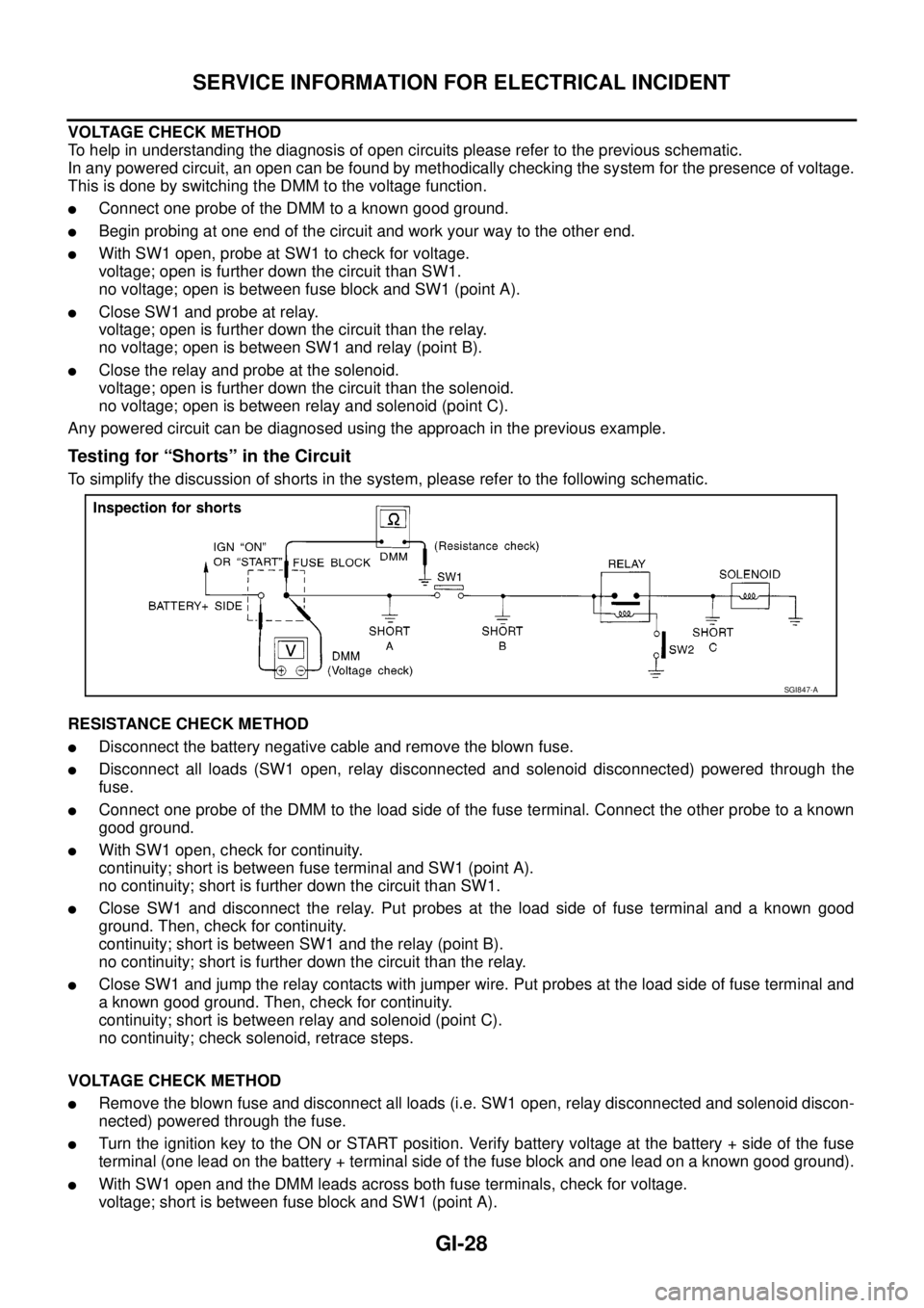
Testing for “Shorts” in the Circuit
To simplify the discussion of shorts in the system, please refer to the following schematic.
RESISTANCE CHECK METHOD
lDisconnect the battery negative cable and remove the blown fuse.
lDisconnect all loads (SW1 open, relay disconnected and solenoid disconnected) powered through the
fuse.
lConnect one probe of the DMM to the load side of the fuse terminal. Connect the other probe to a known
good ground.
lWith SW1 open, check for continuity.
continuity; short is between fuse terminal and SW1 (point A).
no continuity; short is further down the circuit than SW1.
lClose SW1 and disconnect the relay. Put probes at the load side of fuse terminal and a known good
ground. Then, check for continuity.
continuity; short is between SW1 and the relay (point B).
no continuity; short is further down the circuit than the relay.
lClose SW1 and jump the relay contacts with jumper wire. Put probes at the load side of fuse terminal and
a known good ground. Then, check for continuity.
continuity; short is between relay and solenoid (point C).
no continuity; check solenoid, retrace steps.
VOLTAGE CHECK METHOD
lRemove the blown fuse and disconnect all loads (i.e. SW1 open, relay disconnected and solenoid discon-
nected) powered through the fuse.
lTurn the ignition key to the ON or START position. Verify battery voltage at the battery + side of the fuse
terminal (one lead on the battery + terminal side of the fuse block and one lead on a known good ground).
lWith SW1 open and the DMM leads across both fuse terminals, check for voltage.
voltage; short is between fuse block and SW1 (point A).
SGI847-A
Page 1658 of 3171

GI-36
CONTROL UNIT CONFIGURATION PROCEDURE
Work Procedure
EAS001HB
NOTE:
The configuration procedure may differ according to the replaced unit, those always use the work item code to
determinate a appropriate procedure.
Work item code Confirmation procedure Refer page
A1.“Configuration” on CONSULT-II. (At ignition switch LOCK position.)GI-37, "
Configuration (BCM)"
2. Turn ignition switch ON with mechanical key. —
3. “C/U INITIALIZATION” on CONSULT-II. CONSULT-II operation manual NATS.
4. “REGIST I-KEY ID” on CONSULT-II. CONSULT-II operation manual NATS.
B1. “Configuration” on CONSULT-II. (At ignition switch LOCK position.)GI-37, "
Configuration (BCM)"
2. “STEERING LOCK RELEASE” on CONSULT-II. CONSULT-II operation manual NATS.
3. Turn ignition switch ON with mechanical key. —
4. “C/U INITIALIZATION” on CONSULT-II. CONSULT-II operation manual NATS.
5. “REGIST I-KEY ID” on CONSULT-II. CONSULT-II operation manual NATS.
C1. “Configuration” on CONSULT-II. (At ignition switch LOCK position.)GI-37, "
Configuration (BCM)"
2. “STEERING LOCK RELEASE” on CONSULT-II. CONSULT-II operation manual NATS.
3. Turn ignition switch ON with mechanical key. —
4. “C/U INITIALIZATION” on CONSULT-II. CONSULT-II operation manual NATS.
D1. “STEERING LOCK RELEASE” on CONSULT-II. CONSULT-II operation manual NATS.
2. Turn ignition switch ON with mechanical key. —
3. “C/U INITIALIZATION” on CONSULT-II. CONSULT-II operation manual NATS.
4. “REGIST I-KEY ID” on CONSULT-II. CONSULT-II operation manual NATS.
E1. Turn ignition switch ON with mechanical key. —
2. “REGIST I-KEY ID” on CONSULT-II. CONSULT-II operation manual NATS.
F Turn ignition switch ON with mechanical key. —
G1. “Configuration” on CONSULT-II.GI-37, "
Configuration (BCM)"
2. Turn ignition switch ON with mechanical key. —
3. “C/U INITIALIZATION” on CONSULT-II. CONSULT-II operation manual NATS.
H1. “STEERING LOCK RELEASE” on CONSULT-II. CONSULT-II operation manual NATS.
2. “C/U INITIALIZATION” on CONSULT-II. CONSULT-II operation manual NATS.
3. “REGIST I-KEY ID” on CONSULT-II. CONSULT-II operation manual NATS.
J1.“Configuration” on CONSULT-II. (At ignition switch ON position.)GI-37, "
Configuration (BCM)"
2. Erase the DTC (P1612) using CONSULT-II —
I “Configuration” on CONSULT-II. (At ignition switch ON position.)GI-37, "
Configuration (BCM)"
K Turn ignition switch ON with ignition key. —
Page 1659 of 3171
CONTROL UNIT CONFIGURATION PROCEDURE
GI-37
C
D
E
F
G
H
I
J
K
L
MB
GI
Configuration (BCM)EAS001Q6
DESCRIPTION
CONFIGURATION has two functions as follows:
lREAD CONFIGURATION is the function to confirm vehicle configuration of current BCM.
lWRITE CONFIGURATION is the function to write vehicle configuration on BCM.
CAUTION:
lWhen replacing BCM, you must perform WRITE CONFIGURATION with CONSULT-II.
lComplete the procedure of WRITE CONFIGURATION in order.
lIf you set incorrect WRITE CONFIGURATION, incidents will occur.
lConfiguration is different for each vehicle model. Confirm configuration of each vehicle model.
READ CONFIGURATION PROCEDURE
CAUTION:
If CONSULT-II is used with no connection of CONSULT-II CONVERTER, malfunctions might be
detected in self-diagnosis depending on control unit which carry out CAN communication.
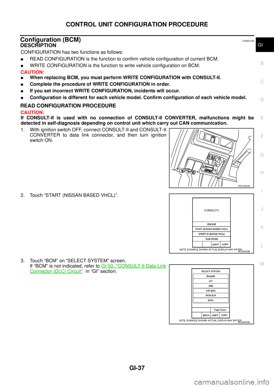
1. With ignition switch OFF, connect CONSULT-II and CONSULT-II
CONVERTER to data link connector, and then turn ignition
switch ON.
2. Touch “START (NISSAN BASED VHCL)”.
3. Touch “BCM” on “SELECT SYSTEM” screen.
If “BCM” is not indicated, refer toGI-50, "
CONSULT-II Data Link
Connector (DLC) Circuit"in “GI” section.
PKIC0644E
BCIA0029E
BCIA0030E
Page 1663 of 3171
CONTROL UNIT CONFIGURATION PROCEDURE
GI-41
C
D
E
F
G
H
I
J
K
L
MB
GI
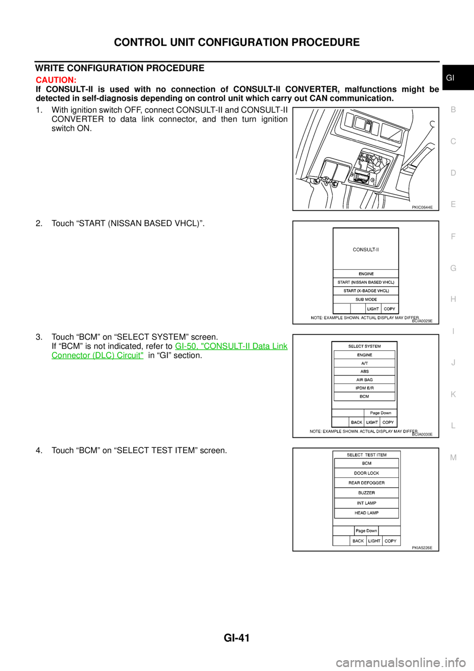
WRITE CONFIGURATION PROCEDURE
CAUTION:
If CONSULT-II is used with no connection of CONSULT-II CONVERTER, malfunctions might be
detected in self-diagnosis depending on control unit which carry out CAN communication.
1. With ignition switch OFF, connect CONSULT-II and CONSULT-II
CONVERTER to data link connector, and then turn ignition
switch ON.
2. Touch “START (NISSAN BASED VHCL)”.
3. Touch “BCM” on “SELECT SYSTEM” screen.
If “BCM” is not indicated, refer toGI-50, "
CONSULT-II Data Link
Connector (DLC) Circuit"in “GI” section.
4. Touch “BCM” on “SELECT TEST ITEM” screen.
PKIC0644E
BCIA0029E
BCIA0030E
PKIA5226E
Page 1669 of 3171

CONSULT-II CHECKING SYSTEM
GI-47
C
D
E
F
G
H
I
J
K
L
MB
GI
CONSULT-II CHECKING SYSTEMPFP:00000
DescriptionEAS001H2
lCONSULT-II is a hand-held type tester. When it is connected with a diagnostic connector equipped on the
vehicle side, it will communicate with the control unit equipped in the vehicle and then enable various
kinds of diagnostic tests.
lRefer to “CONSULT-II Software Operation Manual” for more information.
Function and System ApplicationEAS001H3
x: Applicable
*: Nissan Anti-Theft SystemDiagnostic test
modeFunction
ENGINE
A/T
AIR BAG
ABS
ALL MODE AWD/4WD
BCM
IPDM E/R
MULTI AV
METER
NATS *
Work supportThis mode enables a technician to adjust some devices
faster and more accurately by following the indications
on CONSULT-II.x---´´--- -
Self-diagnostic
resultsSelf-diagnostic results can be read and erased quickly. x x x x x´´´´x
Trouble diagnostic
recordCurrent self-diagnostic results and all trouble diagnostic
records previously stored can be read.--x------ -
Data monitor Input/Output data in the ECU can be read. x x - x x´´´´-
CAN diagnosis
support monitorThe communication condition of CAN communication
line can be indicated.xx - xx´´´´-
Active testDiagnostic Test Mode in which CONSULT-II drives some
actuators apart from the ECU and also shifts some
parameters in a specified range.x- -x-´´-- -
DTC confirmationThe results of SRT (System Readiness Test) and the
self-diagnosis status/result can be confirmed.x----- - -- -
DTC work supportThe operating condition to confirm Diagnosis Trouble
Codes can be selected.-x------- -
ECM (ECU/TCM)
part numberECM (ECU/TCM) part number can be read. x x - x x´-´--
ECU discrimi-
nated No.Classification number of a replacement ECU can be read
to prevent an incorrect ECU from being installed.--x------ -
Function testThis mode can show results of self-diagnosis of ECU
with either “OK” or “NG”. For engines, more practical
tests regarding sensor/switches and/or actuators are
available.xxxx-- - - - -
Control unit initial-
izationAll registered ignition key IDs in NATS components can
be initialized and new IDs can be registered.------ - -- x
AV C O M M m o n i t o rIndicates the communication condition of AV communi-
cation.- ----- -´--
ConfigurationThe vehicle configuration can be read and written on
brand-new ECU- ----´--- -
Page 1671 of 3171
CONSULT-II CHECKING SYSTEM
GI-49
C
D
E
F
G
H
I
J
K
L
MB
GI
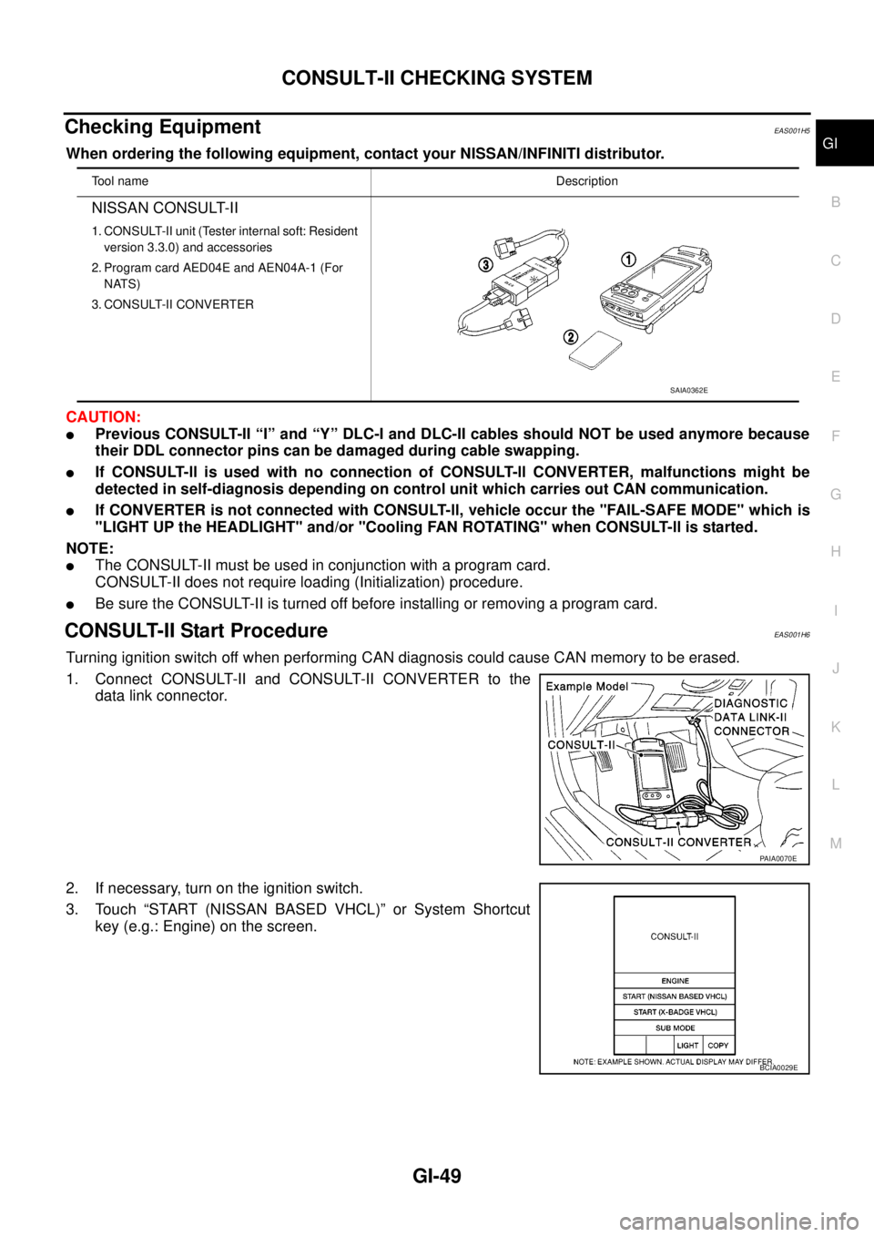
Checking EquipmentEAS001H5
When ordering the following equipment, contact your NISSAN/INFINITI distributor.
CAUTION:
lPrevious CONSULT-II “I” and “Y” DLC-I and DLC-II cables should NOT be used anymore because
their DDL connector pins can be damaged during cable swapping.
lIf CONSULT-ll is used with no connection of CONSULT-ll CONVERTER, malfunctions might be
detected in self-diagnosis depending on control unit which carries out CAN communication.
lIf CONVERTER is not connected with CONSULT-ll, vehicle occur the "FAIL-SAFE MODE" which is
"LIGHT UP the HEADLIGHT" and/or "Cooling FAN ROTATING" when CONSULT-ll is started.
NOTE:
lThe CONSULT-II must be used in conjunction with a program card.
CONSULT-II does not require loading (Initialization) procedure.
lBe sure the CONSULT-II is turned off before installing or removing a program card.
CONSULT-II Start ProcedureEAS001H6
Turning ignition switch off when performing CAN diagnosis could cause CAN memory to be erased.
1. Connect CONSULT-II and CONSULT-II CONVERTER to the
data link connector.
2. If necessary, turn on the ignition switch.
3. Touch “START (NISSAN BASED VHCL)” or System Shortcut
key (e.g.: Engine) on the screen.
Tool nameDescription
NISSAN CONSULT-II
1. CONSULT-II unit (Tester internal soft: Resident
version 3.3.0) and accessories
2. Program card AED04E and AEN04A-1 (For
NATS)
3. CONSULT-II CONVERTER
SAIA0362E
PAIA0070E
BCIA0029E