2005 NISSAN NAVARA ignition
[x] Cancel search: ignitionPage 1745 of 3171
REAR WINDOW DEFOGGER
GW-59
C
D
E
F
G
H
J
K
L
MA
B
GW
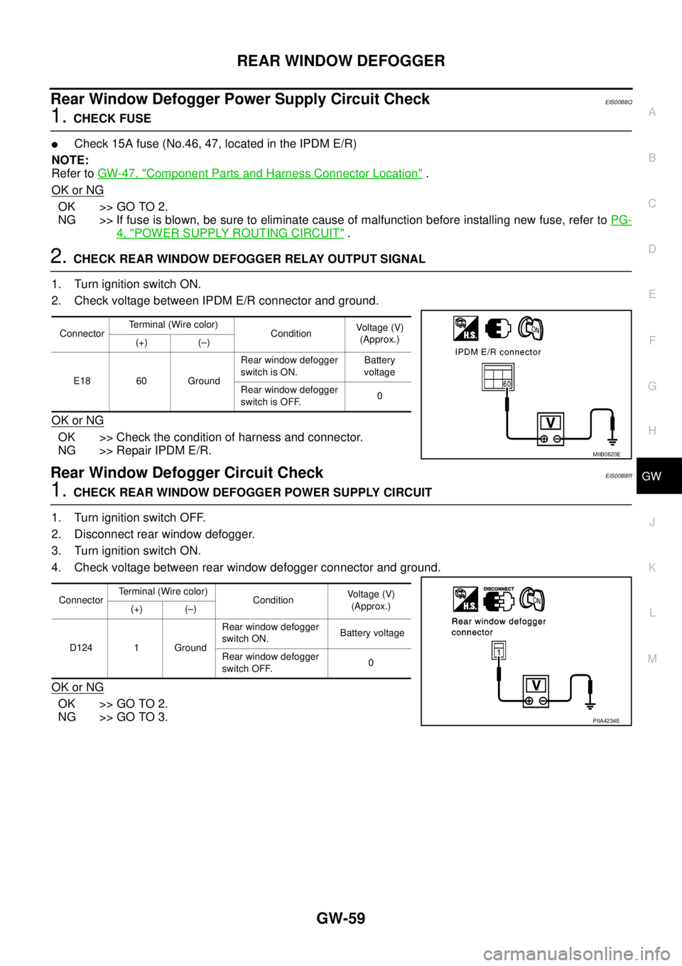
Rear Window Defogger Power Supply Circuit CheckEIS00B8Q
1.CHECK FUSE
lCheck 15A fuse (No.46, 47, located in the IPDM E/R)
NOTE:
Refer toGW-47, "
Component Parts and Harness Connector Location".
OK or NG
OK >> GO TO 2.
NG >> If fuse is blown, be sure to eliminate cause of malfunction before installing new fuse, refer toPG-
4, "POWER SUPPLY ROUTING CIRCUIT".
2.CHECK REAR WINDOW DEFOGGER RELAY OUTPUT SIGNAL
1. Turn ignition switch ON.
2. Check voltage between IPDM E/R connector and ground.
OK or NG
OK >> Check the condition of harness and connector.
NG >> Repair IPDM E/R.
Rear Window Defogger Circuit CheckEIS00B8R
1.CHECK REAR WINDOW DEFOGGER POWER SUPPLY CIRCUIT
1. Turn ignition switch OFF.
2. Disconnect rear window defogger.
3. Turn ignition switch ON.
4. Check voltage between rear window defogger connector and ground.
OK or NG
OK >> GO TO 2.
NG >> GO TO 3.
ConnectorTerminal (Wire color)
ConditionVoltag e (V)
(Approx.)
(+) (–)
E18 60 GroundRear window defogger
switch is ON.Battery
voltage
Rear window defogger
switch is OFF.0
MIIB0620E
ConnectorTerminal (Wire color)
ConditionVo l ta g e (V )
(Approx.)
(+) (–)
D124 1 GroundRear window defogger
switch ON.Battery voltage
Rear window defogger
switch OFF.0
PIIA4234E
Page 1746 of 3171
GW-60
REAR WINDOW DEFOGGER
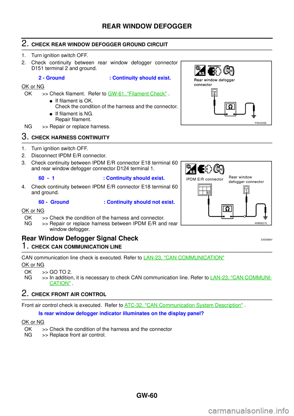
2.CHECK REAR WINDOW DEFOGGER GROUND CIRCUIT
1. Turn ignition switch OFF.
2. Check continuity between rear window defogger connector
D151 terminal 2 and ground.
OK or NG
OK >> Check filament. Refer toGW-61, "Filament Check".
lIf filament is OK.
Check the condition of the harness and the connector.
lIf filament is NG.
Repair filament.
NG >> Repair or replace harness.
3.CHECK HARNESS CONTINUITY
1. Turn ignition switch OFF.
2. Disconnect IPDM E/R connector.
3. Check continuity between IPDM E/R connector E18 terminal 60
and rear window defogger connector D124 terminal 1.
4. Check continuity between IPDM E/R connector E18 terminal 60
and ground.
OK or NG
OK >> Check the condition of the harness and connector.
NG >> Repair or replace harness between IPDM E/R and rear
window defogger.
Rear Window Defogger Signal CheckEIS00B8V
1.CHECK CAN COMMUNICATION LINE
CAN communication line check is executed. Refer toLAN-23, "
CAN COMMUNICATION"
OK or NG
OK >> GO TO 2.
NG >> In addition, it is necessary to check CAN communication line. Refer toLAN-23, "
CAN COMMUNI-
CATION".
2.CHECK FRONT AIR CONTROL
Front air control check is executed. Refer toAT C - 3 2 , "
CAN Communication System Description".
OK or NG
OK >> Check the condition of the harness and the connector
NG >> Replace front air control.2 - Ground : Continuity should exist.
PIIA4235E
60 - 1 : Continuity should exist.
60 - Ground : Continuity should not exist.
MIIB0621E
Is rear window defogger indicator illuminates on the display panel?
Page 1757 of 3171
IDX-5
A
C
D
E
F
G
H
I
J
K
L B
IDX
ALPHABETICAL INDEX
HSEAT - Wiring diagram .......................SE-14,SE-17
I
IATS - Wiring diagram .....................................EC-100
Identification plate ...............................................GI-57
Idle speed ..........................................................EC-38
Ignition key hole illumination .............................LT-145
ILL - Wiring diagram .........................................LT-166
Illumination .......................................................LT-162
In vehicle sensor ...........................ATC-108,ATC-118
INJE/PW - Wiring diagram ...............................EC-284
INJECT - Wiring diagram .....EC-128,EC-240,EC-289
Injection nozzle .......EM-44,EC-123,EC-125,EC-237
Injector adjustment value ...................EC-271,EC-273
Injector adjustment value registration ................EC-25
Input clutch solenoid valve .................AT-132,AT-134
Instrument panel ..................................................IP-10
INT/V - Wiring diagram ....................................EC-315
Intake air control valve control solenoid valve .EC-314
Intake air temperature sensor ............................EC-98
Intake door control linkage adjustment ............ATC-79
Intake door motor ..........ATC-77,ATC-129,MTC-109
Intake manifold ..................................................EM-20
Intake sensor ..ATC-114,ATC-120,MTC-95,MTC-99
Interior .................................................................EI-33
Interior lamp ......................................................LT-145
Interior lamp on-off control ................................LT-145
IPDM (Intelligent power distribution module engine
room) .................................................................PG-14
ISO 15031-2 Terminology ..................................GI-61
J
Jacking points .....................................................GI-52
K
Key illumination ................................................LT-145
KEYLES - Wiring diagram ..................................BL-93
L
Leaf spring (rear) ..............................................RSU-7
Length (Dimensions) ..........................................GI-60
License lamp ....................................................LT-125
Lifting points .......................................................GI-52
Line pressure solenoid valve ...........................AT-114
Line pressure test (A/T) .....................................AT-44
Liquid gasket application ................EM-5,LU-2,CO-2
Location of electrical units .................................PG-71
Low coast brake solenoid valve ..........AT-152,AT-154
Lubricant (R134a) A/C ......................ATC-24,MTC-24
Lubricants ..........................................................MA-14
Lubrication circuit (engine) ..................................LU-4
Lubrication oil A/C ............................ATC-24,MTC-24
Lubrication-locks, hinges and hood latches .......MA-39
M
MAFS - Wiring diagram .....................................EC-94
Magnet clutch .ATC-87,ATC-143,MTC-79,MTC-123
MAIN - Wiring diagram ......................................EC-72
Main drive gear (M/T) ........................................MT-21
Mainshaft (M/T) ..................................................MT-21
Major overhaul (Final drive)FFD-17,RFD-15,RFD-82
Major overhaul (Transfer) ................................TF-112
Malfunction indicator (MI) ..................................EC-28
Map lamp ..........................................................LT-145
Mass air flow sensor (MAFS) .............................EC-92
Master cylinder (brake) ......................................BR-17
Master cylinder (clutch) ........................................CL-9
Meter .....................................................................DI-4
METER - Wiring diagram ....................................DI-10
MI & data link connectors circuit ......................EC-354
MIL/DL - Wiring diagram ..................................EC-354
Mode door control linkage adjustment ............ATC-65,
MTC-59
Mode door motor ............ATC-63,ATC-130,MTC-58,
MTC-110
Model variation ...................................................GI-56
Multiport fuel injection precautions .......................GI-6
N
NATS - Wiring diagram ....................................BL-173
NATS (Nissan anti-theft system) precautions .......GI-3
NVH troubleshooting (AX) .................................FAX-4
NVH troubleshooting (BR) ...................................BR-5
NVH troubleshooting (EM) ................................EM-10
NVH troubleshooting (Final drive) ........FFD-6,RFD-7,
RFD-39
NVH troubleshooting (M/T) ..................................MT-6
NVH troubleshooting (Propeller shaft) .................PR-2
NVH troubleshooting (ST) ....................................PS-5
NVH troubleshooting (Transfer) .........................TF-11
NVH troubleshooting (WT)NVH troubleshooting (WT) .
WT-2
O
Oil cooler (engine) .............................................LU-11
Oil filter .................................................................LU-8
Oil pan (engine) ................................................EM-36
Oil pressure (engine) ...........................................LU-5
Oil pump (A/T) .................................................AT-281
Oil pump (engine) ..............................................LU-14
Oil seal replacement (engine) ...........................EM-70
Oil seal replacement (front of final drive) ...........FFD-9
Oil seal replacement (side of final drive) ..........FFD-13
On board diagnostic system ..............................EC-27
Operating cylinder (clutch) .................................CL-11
Overheat ..........................................................EC-132
Oversize piston ...............................................EM-129
Page 1761 of 3171
IP-2
PRECAUTIONS
PRECAUTIONS
PFP:00001
Precautions for Supplemental Restraint System (SRS) “AIR BAG” and “SEAT
BELT PRE-TENSIONER”
EIS00DZ8
The Supplemental Restraint System such as “AIR BAG” and “SEAT BELT PRE-TENSIONER”, used along
with a front seat belt, helps to reduce the risk or severity of injury to the driver and front passenger for certain
types of collision. Information necessary to service the system safely is included in the SRS and SB section of
this Service Manual.
WARNING:
lTo avoid rendering the SRS inoperative, which could increase the risk of personal injury or death
in the event of a collision which would result in air bag inflation, all maintenance must be per-
formed by an authorized NISSAN/INFINITI dealer.
lImproper maintenance, including incorrect removal and installation of the SRS, can lead to per-
sonal injury caused by unintentional activation of the system. For removal of Spiral Cable and Air
Bag Module, see the SRS section.
lDo not use electrical test equipment on any circuit related to the SRS unless instructed to in this
Service Manual. SRS wiring harnesses can be identified by yellow and/or orange harnesses or
harness connectors.
Precautions for SRS “AIR BAG” and “SEAT BELT PRE-TENSIONER” ServiceEIS00DZ4
lDo not use electrical test equipment to check SRS circuits unless instructed to in this Service Manual.
lBefore servicing the SRS, turn ignition switch OFF, disconnect both battery cables and wait at least 3 min-
utes.
For approximately 3 minutes after the cables are removed, it is still possible for the air bag and seat belt
pre-tensioner to deploy. Therefore, do not work on any SRS connectors or wires until at least 3 minutes
have passed.
lThe air bag diagnosis sensor unit must always be installed with the arrow marks “Ü” pointing toward the
front of the vehicle for proper operation. Also check the air bag diagnosis sensor unit for cracks, deformi-
ties or rust before installation and replace as required.
lThe spiral cable must be aligned with the neutral position since its rotations are limited. Do not attempt to
turn steering wheel or column after removal of steering gear.
lHandle air bag module carefully. Always place driver and front passenger air bag modules with the pad
side facing upward and seat mounted front side air bag module standing with the stud bolt side facing
down.
lConduct self-diagnosis to check entire SRS for proper function after replacing any components.
lAfter air bag inflates, the front instrument panel assembly should be replaced if damaged.
Page 1772 of 3171
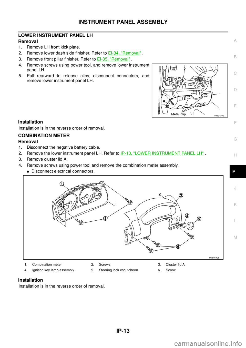
INSTRUMENT PANEL ASSEMBLY
IP-13
C
D
E
F
G
H
J
K
L
MA
B
IP
LOWER INSTRUMENT PANEL LH
Removal
1. Remove LH front kick plate.
2. Remove lower dash side finisher. Refer toEI-34, "
Removal".
3. Remove front pillar finisher. Refer toEI-35, "
Removal".
4. Remove screws using power tool, and remove lower instrument
panel LH.
5. Pull rearward to release clips, disconnect connectors, and
remove lower instrument panel LH.
Installation
Installation is in the reverse order of removal.
COMBINATION METER
Removal
1. Disconnect the negative battery cable.
2. Remove the lower instrument panel LH. Refer toIP-13, "
LOWER INSTRUMENT PANEL LH".
3. Remove cluster lid A.
4. Remove screws using power tool and remove the combination meter assembly.
lDisconnect electrical connectors.
Installation
Installation is in the reverse order of removal.
MIIB9139E
1. Combination meter 2. Screws 3. Cluster lid A
4. Ignition key lamp assembly 5. Steering lock escutcheon 6. Screw
MIIB9140E
Page 1779 of 3171

LAN-2
Wiring Diagram — CAN — ..................................... 82
Check Sheet ........................................................... 83
CHECK SHEET RESULTS (EXAMPLE) ............. 85
CAN SYSTEM (TYPE 5) ........................................... 96
Component Parts and Harness Connector Location... 96
Schematic ............................................................... 96
Wiring Diagram — CAN — ..................................... 96
Check Sheet ........................................................... 97
CHECK SHEET RESULTS (EXAMPLE) ............. 99
CAN SYSTEM (TYPE 6) .........................................112
Component Parts and Harness Connector Location.112
Schematic .............................................................112
Wiring Diagram — CAN — ...................................112
Check Sheet .........................................................113
CHECK SHEET RESULTS (EXAMPLE) ...........115
CAN SYSTEM (TYPE 7) .........................................125
Component Parts and Harness Connector Location.125
Schematic .............................................................125
Wiring Diagram — CAN — ...................................125
Check Sheet .........................................................126
CHECK SHEET RESULTS (EXAMPLE) ...........128
CAN SYSTEM (TYPE 8) .........................................139
Component Parts and Harness Connector Location.139
Schematic .............................................................139
Wiring Diagram — CAN — ...................................139
Check Sheet .........................................................140
CHECK SHEET RESULTS (EXAMPLE) ...........142
CAN SYSTEM (TYPE 9) .........................................152
Component Parts and Harness Connector Location.152
Schematic .............................................................152
Wiring Diagram — CAN — ...................................152
Check Sheet .........................................................153
CHECK SHEET RESULTS (EXAMPLE) ...........155
CAN SYSTEM (TYPE 10) .......................................166
Component Parts and Harness Connector Location.166
Schematic .............................................................166
Wiring Diagram — CAN — ...................................166
Check Sheet .........................................................167
CHECK SHEET RESULTS (EXAMPLE) ...........169
CAN SYSTEM (TYPE 11) ........................................181
Component Parts and Harness Connector Location.181
Schematic .............................................................181
Wiring Diagram — CAN — ...................................181
Check Sheet .........................................................182
CHECK SHEET RESULTS (EXAMPLE) ...........185
CAN SYSTEM (TYPE 12) .......................................198
Component Parts and Harness Connector Location.198
Schematic .............................................................198
Wiring Diagram — CAN — ...................................198
Check Sheet .........................................................199
CHECK SHEET RESULTS (EXAMPLE) ...........201
CAN SYSTEM (TYPE 13) .......................................213
Component Parts and Harness Connector Location.213Schematic .............................................................213
Wiring Diagram — CAN — ...................................213
Check Sheet .........................................................214
CHECK SHEET RESULTS (EXAMPLE) ............217
CAN SYSTEM (TYPE 14) ........................................230
Component Parts and Harness Connector Location.230
Schematic .............................................................230
Wiring Diagram — CAN — ...................................230
Check Sheet .........................................................231
CHECK SHEET RESULTS (EXAMPLE) ............234
CAN SYSTEM (TYPE 15) ........................................248
Component Parts and Harness Connector Location.248
Schematic .............................................................248
Wiring Diagram — CAN — ...................................248
Check Sheet .........................................................249
CHECK SHEET RESULTS (EXAMPLE) ............252
CAN SYSTEM (TYPE 16) ........................................267
Component Parts and Harness Connector Location.267
Schematic .............................................................267
Wiring Diagram — CAN — ...................................267
Check Sheet .........................................................268
CHECK SHEET RESULTS (EXAMPLE) ............270
CAN SYSTEM (TYPE 17) ........................................279
Component Parts and Harness Connector Location.279
Schematic .............................................................279
Wiring Diagram — CAN — ...................................279
Check Sheet .........................................................280
CHECK SHEET RESULTS (EXAMPLE) ............282
TROUBLE DIAGNOSIS FOR SYSTEM ..................292
Inspection Between TCM and Data Link Connector
Circuit ....................................................................292
Inspection Between TCM and NAVI Control Unit Cir-
cuit ........................................................................293
Inspection Between NAVI Control Unit and Data
Link Connector Circuit ...........................................295
Inspection Between Data Link Connector and ABS
Actuator and Electric Unit (Control Unit) Circuit ....296
ECM Circuit Inspection for M/T Models ................297
ECM Circuit Inspection for A/T Models .................298
TCM Circuit Inspection ..........................................298
NAVI Control Unit Circuit Inspection .....................299
Differential Lock Control Unit Circuit Inspection ....299
Front Air Control Circuit Inspection .......................300
Data Link Connector Circuit Inspection .................300
BCM Circuit Inspection .........................................301
Combination Meter Circuit Inspection ...................301
Transfer Control Unit Circuit Inspection ................302
ABS Actuator and Electric Unit (Control Unit) Circuit
Inspection ..............................................................302
IPDM E/R Circuit Inspection .................................303
CAN Communication Circuit Inspection ................303
IPDM E/R Ignition Relay Circuit Inspection ...........304
Page 1780 of 3171
![NISSAN NAVARA 2005 Repair Workshop Manual PRECAUTIONS
LAN-3
[CAN]
C
D
E
F
G
H
I
J
L
MA
B
LAN
[CAN]PRECAUTIONSPFP:00001
Precautions for Supplemental Restraint System (SRS) “AIR BAG” and “SEAT
BELT PRE-TENSIONER”
EKS00Q9Y
The Supplement NISSAN NAVARA 2005 Repair Workshop Manual PRECAUTIONS
LAN-3
[CAN]
C
D
E
F
G
H
I
J
L
MA
B
LAN
[CAN]PRECAUTIONSPFP:00001
Precautions for Supplemental Restraint System (SRS) “AIR BAG” and “SEAT
BELT PRE-TENSIONER”
EKS00Q9Y
The Supplement](/manual-img/5/57362/w960_57362-1779.png)
PRECAUTIONS
LAN-3
[CAN]
C
D
E
F
G
H
I
J
L
MA
B
LAN
[CAN]PRECAUTIONSPFP:00001
Precautions for Supplemental Restraint System (SRS) “AIR BAG” and “SEAT
BELT PRE-TENSIONER”
EKS00Q9Y
The Supplemental Restraint System such as “AIR BAG” and “SEAT BELT PRE-TENSIONER”, used along
with a front seat belt, helps to reduce the risk or severity of injury to the driver and front passenger for certain
types of collision. Information necessary to service the system safely is included in the SRS and SB section of
this Service Manual.
WARNING:
lTo avoid rendering the SRS inoperative, which could increase the risk of personal injury or death
in the event of a collision which would result in air bag inflation, all maintenance must be per-
formed by an authorized NISSAN/INFINITI dealer.
lImproper maintenance, including incorrect removal and installation of the SRS, can lead to per-
sonal injury caused by unintentional activation of the system. For removal of Spiral Cable and Air
Bag Module, see the SRS section.
lDo not use electrical test equipment on any circuit related to the SRS unless instructed to in this
Service Manual. SRS wiring harnesses can be identified by yellow and/or orange harnesses or
harness connectors.
Precautions When Using CONSULT-IIEKS00LBE
When connecting CONSULT-II to data link connector, connect them through CONSULT-II CONVERTER.
CAUTION:
If CONSULT-II is used with no connection of CONSULT-II CONVERTER, malfunctions might be
detected in self-diagnosis depending on control unit which carry out CAN communication.
CHECK POINTS FOR USING CONSULT-II
1. Has CONSULT-II been used without connecting CONSULT-II CONVERTER on this vehicle?
–If YES, GO TO 2.
–If NO, GO TO 5.
2. Is there any indication other than indications relating to CAN communication system in the self-diagnosis
results?
–If YES, GO TO 3.
–If NO, GO TO 4.
3. Based on self-diagnosis results unrelated to CAN communication, carry out the inspection.
4. Malfunctions may be detected in self-diagnosis depending on control units carrying out CAN communica-
tion. Therefore, erase the self-diagnosis results.
5. Diagnose CAN communication system. Refer toLAN-5, "
TROUBLE DIAGNOSES WORK FLOW".
Precautions For Trouble DiagnosisEKS00LBF
CAN SYSTEM
lDo not apply voltage of 7.0 V or higher to the measurement terminals.
lUse the tester with its open terminal voltage being 7.0 V or less.
lBe sure to turn ignition switch off and disconnect negative battery terminal before checking the circuit.
Precautions For Harness RepairEKS00LBG
CAN SYSTEM
lSolder the repaired parts, and wrap with tape. [Frays of twisted
line must be within 110 mm (4.33 in).]
PKIA0306E
Page 1832 of 3171
![NISSAN NAVARA 2005 Repair Workshop Manual CAN SYSTEM (TYPE 1)
LAN-55
[CAN]
C
D
E
F
G
H
I
J
L
MA
B
LAN
Case 10
Check IPDM E/R ignition relay circuit continuously sticks “OFF”. Refer toLAN-304, "IPDM E/R Ignition Relay
Circuit Inspection".
NISSAN NAVARA 2005 Repair Workshop Manual CAN SYSTEM (TYPE 1)
LAN-55
[CAN]
C
D
E
F
G
H
I
J
L
MA
B
LAN
Case 10
Check IPDM E/R ignition relay circuit continuously sticks “OFF”. Refer toLAN-304, "IPDM E/R Ignition Relay
Circuit Inspection".](/manual-img/5/57362/w960_57362-1831.png)
CAN SYSTEM (TYPE 1)
LAN-55
[CAN]
C
D
E
F
G
H
I
J
L
MA
B
LAN
Case 10
Check IPDM E/R ignition relay circuit continuously sticks “OFF”. Refer toLAN-304, "IPDM E/R Ignition Relay
Circuit Inspection".
Case 11
Check IPDM E/R ignition relay circuit continuously sticks “ON”. Refer toLAN-304, "IPDM E/R Ignition Relay
Circuit Inspection".
PKIC1736E
PKIC1737E