2005 NISSAN NAVARA ignition
[x] Cancel search: ignitionPage 1473 of 3171
PRIMARY TIMING CHAIN
EM-91
C
D
E
F
G
H
I
J
K
L
MA
EM
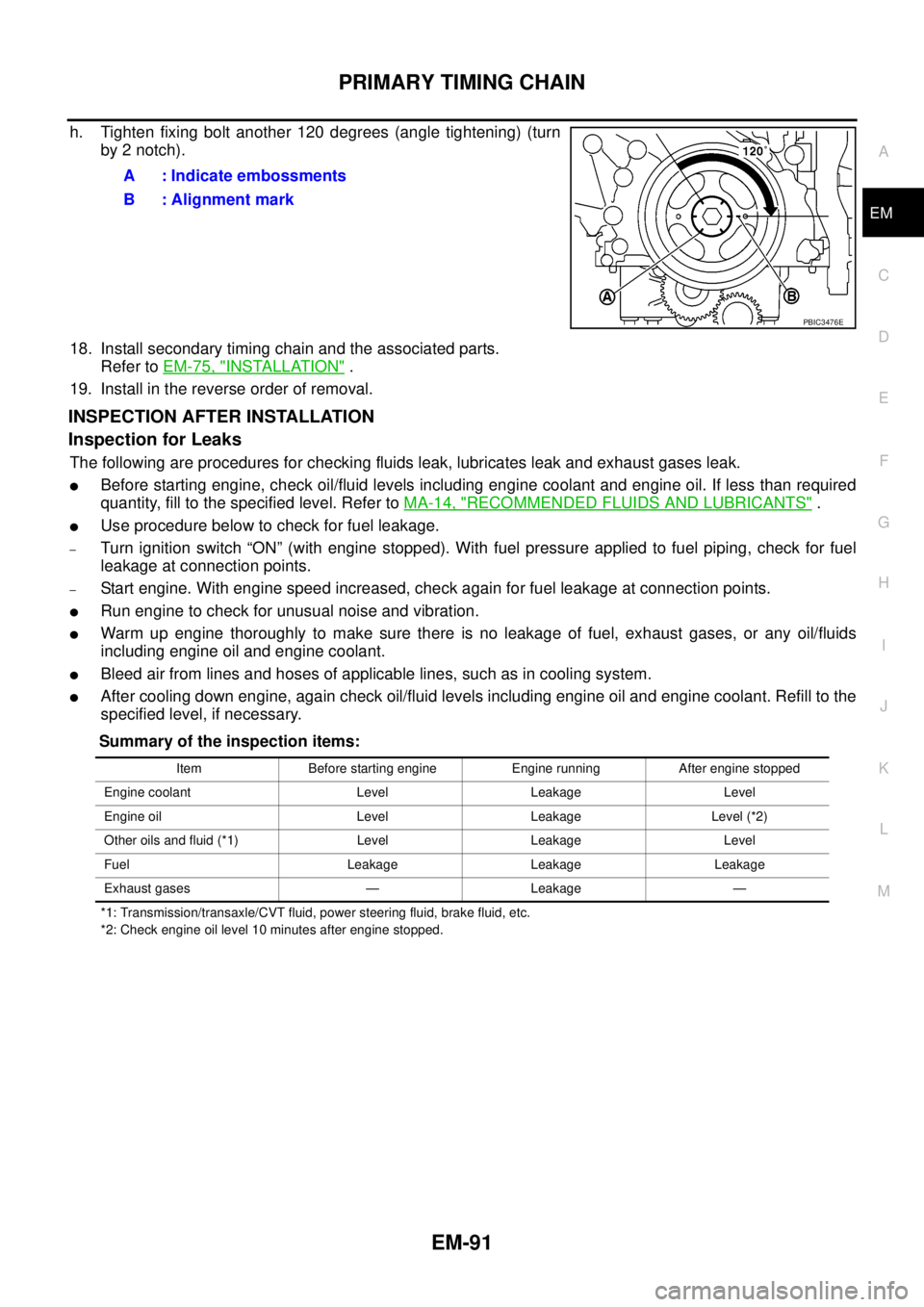
h. Tighten fixing bolt another 120 degrees (angle tightening) (turn
by 2 notch).
18. Install secondary timing chain and the associated parts.
Refer toEM-75, "
INSTALLATION".
19. Install in the reverse order of removal.
INSPECTION AFTER INSTALLATION
Inspection for Leaks
The following are procedures for checking fluids leak, lubricates leak and exhaust gases leak.
lBefore starting engine, check oil/fluid levels including engine coolant and engine oil. If less than required
quantity, fill to the specified level. Refer toMA-14, "
RECOMMENDED FLUIDS AND LUBRICANTS".
lUse procedure below to check for fuel leakage.
–Turn ignition switch “ON” (with engine stopped). With fuel pressure applied to fuel piping, check for fuel
leakage at connection points.
–Start engine. With engine speed increased, check again for fuel leakage at connection points.
lRun engine to check for unusual noise and vibration.
lWarm up engine thoroughly to make sure there is no leakage of fuel, exhaust gases, or any oil/fluids
including engine oil and engine coolant.
lBleed air from lines and hoses of applicable lines, such as in cooling system.
lAfter cooling down engine, again check oil/fluid levels including engine oil and engine coolant. Refill to the
specified level, if necessary.
Summary of the inspection items:
*1: Transmission/transaxle/CVT fluid, power steering fluid, brake fluid, etc.
*2: Check engine oil level 10 minutes after engine stopped.
A : Indicate embossments
B : Alignment mark
PBIC3476E
Item Before starting engine Engine running After engine stopped
Engine coolant Level Leakage Level
Engine oil Level Leakage Level (*2)
Other oils and fluid (*1) Level Leakage Level
Fuel Leakage Leakage Leakage
Exhaust gases — Leakage —
Page 1474 of 3171
EM-92
CYLINDER HEAD
CYLINDER HEAD
PFP:11041
On-Vehicle ServiceEBS01E6A
CHECKING COMPRESSION PRESSURE
1. Warm up engine thoroughly. Then, stop it.
2. Using CONSULT-II, make sure no error codes are indicated for self-diagnosis items. Refer toEC-38,
"Basic Inspection".
lDo not disconnect CONSULT-II until the end of this operation; it will be used to check engine rpm and
for error detection at the end of this operation.
3. Disconnect the battery cable from the negative terminal.
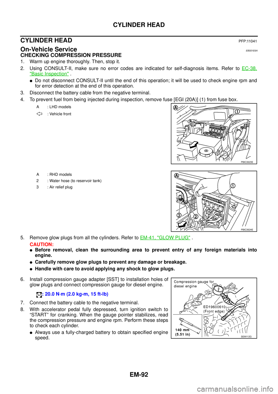
4. To prevent fuel from being injected during inspection, remove fuse [EGI (20A)] (1) from fuse box.
5. Remove glow plugs from all the cylinders. Refer toEM-41, "
GLOW PLUG".
CAUTION:
lBefore removal, clean the surrounding area to prevent entry of any foreign materials into
engine.
lCarefully remove glow plugs to prevent any damage or breakage.
lHandle with care to avoid applying any shock to glow plugs.
6. Install compression gauge adapter [SST] to installation holes of
glow plugs and connect compression gauge for diesel engine.
7. Connect the battery cable to the negative terminal.
8. With accelerator pedal fully depressed, turn ignition switch to
“START” for cranking. When the gauge pointer stabilizes, read
the compression pressure and engine rpm. Perform these steps
to check each cylinder.
lAlways use a fully-charged battery to obtain specified engine
speed.
A : LHD models
: Vehicle front
PBIC3623E
A : RHD models
2 : Water hose (to reservoir tank)
3:Airreliefplug
PBIC3624E
: 20.0 N·m (2.0 kg-m, 15 ft-lb)
SEM112G
Page 1475 of 3171
CYLINDER HEAD
EM-93
C
D
E
F
G
H
I
J
K
L
MA
EM
Compression pressure
Unit: kPa (bar, kg/cm2, psi)/rpm
lWhen engine rpm is out of the specified range, check the specific gravity of battery liquid. Measure
again under corrected conditions.
lIf engine rpm exceeds the limit, check valve clearance and combustion chamber components (valves,
valve seats, cylinder head gaskets, piston rings, pistons, cylinder bores, cylinder block upper and lower
surfaces) and measure again.
lIf compression pressure is low in some cylinders, apply engine oil from glow plug installation hole. Then
check pressure again.
–If compression pressure becomes normal after applying engine oil, piston ring may be worn or dam-
aged. Check piston ring for malfunction. If any, replace piston ring.
–If compression pressure is still low after applying engine oil, valve may be malfunctioning. Check valve
for malfunction. If contact malfunction is found, replace valve or valve seat.
lIf compression pressure in adjacent two cylinders is low after applying engine oil, pressure may be
leaking from gasket. In this case, replace cylinder head gasket.
9. Complete this operation as follows:
a. Turn the ignition switch to “OFF”.
b. Disconnect the battery cable from the negative terminal.
c. Install glow plug and install all the parts removed in step 4.
d. Install fuse [EGI (20A)].
e. Connect the battery cable to the negative terminal.
f. Using CONSULT-II make sure no DTC is indicated for items of self-diagnosis.
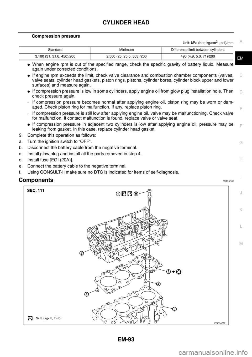
ComponentsEBS01EKC
Standard Minimum Difference limit between cylinders
3,100 (31, 31.6, 450)/200 2,500 (25, 25.5, 363)/200 490 (4.9, 5.0, 71)/200
PBIC3477E
Page 1480 of 3171

EM-98
CYLINDER HEAD
lBefore installing, remove carbon depositing on mounting hole of glow plug with a reamer.
6. Install engine coolant temperature sensor.
7. Install in the reverse order of removal.
INSPECTION AFTER INSTALLATION
Inspection for Leaks
The following are procedures for checking fluids leak, lubricates leak and exhaust gases leak.
lBefore starting engine, check oil/fluid levels including engine coolant and engine oil. If less than required
quantity, fill to the specified level. Refer toMA-14, "
RECOMMENDED FLUIDS AND LUBRICANTS".
lUse procedure below to check for fuel leakage.
–Turn ignition switch “ON” (with engine stopped). With fuel pressure applied to fuel piping, check for fuel
leakage at connection points.
–Start engine. With engine speed increased, check again for fuel leakage at connection points.
lRun engine to check for unusual noise and vibration.
lWarm up engine thoroughly to make sure there is no leakage of fuel, exhaust gases, or any oil/fluids
including engine oil and engine coolant.
lBleed air from lines and hoses of applicable lines, such as in cooling system.
lAfter cooling down engine, again check oil/fluid levels including engine oil and engine coolant. Refill to the
specified level, if necessary.
Summary of the inspection items:
*1: Transmission/transaxle/CVT fluid, power steering fluid, brake fluid, etc.
*2: Check engine oil level 10 minutes after engine stopped.Item Before starting engine Engine running After engine stopped
Engine coolant Level Leakage Level
Engine oil Level Leakage Level (*2)
Other oils and fluid (*1) Level Leakage Level
Fuel Leakage Leakage Leakage
Exhaust gases — Leakage —
Page 1625 of 3171
PRECAUTIONS
GI-3
C
D
E
F
G
H
I
J
K
L
MB
GI
PRECAUTIONSPFP:00001
DescriptionEAS001GG
Observe the following precautions to ensure safe and proper servicing. These precautions are not
described in each individual section.
Precautions for Supplemental Restraint System (SRS) “AIR BAG” and “SEAT
BELT PRE-TENSIONER”
EAS001GH
The Supplemental Restraint System such as “AIR BAG” and “SEAT BELT PRE-TENSIONER”, used along
with a front seat belt, helps to reduce the risk or severity of injury to the driver and front passenger for certain
types of collision. Information necessary to service the system safely is included in the SRS and SB section of
this Service Manual.
WARNING:
lTo avoid rendering the SRS inoperative, which could increase the risk of personal injury or death
in the event of a collision which would result in air bag inflation, all maintenance must be per-
formed by an authorized NISSAN/INFINITI dealer.
lImproper maintenance, including incorrect removal and installation of the SRS, can lead to per-
sonal injury caused by unintentional activation of the system. For removal of Spiral Cable and Air
Bag Module, see the SRS section.
lDo not use electrical test equipment on any circuit related to the SRS unless instructed to in this
Service Manual. SRS wiring harnesses can be identified by yellow and/or orange harnesses or
harness connectors.
Precautions for NATS (NISSAN ANTI-THEFT SYSTEM)EAS001GI
NATS will immobilize the engine if someone tries to start it without the registered key of NATS.
Both of the originally supplied ignition key IDs have been NATS registered.
The security indicator is located on the instrument panel. The indicator blinks when the immobilizer system is
functioning.
Therefore, NATS warns outsiders that the vehicle is equipped with the anti-theft system.
lWhen NATS detects trouble, the security indicator lamp lights up while ignition switch is in "ON" position.
This lighting up indicates that the anti-theft is not functioning, so prompt service is required.
lWhen servicing NATS (trouble diagnoses, system initialization and additional registration of other NATS
ignition key IDs), CONSULT-II hardware and CONSULT-II NATS software is necessary.
Regarding the procedures of NATS initialization and NATS ignition key ID registration, refer to CONSULT-
II operation manual, NATS.
Therefore, CONSULT-II NATS software (program card and operation manual) must be kept strictly con-
fidential to maintain the integrity of the anti-theft function.
lWhen servicing NATS (trouble diagnoses, system initialization and additional registration of other NATS
ignition key IDs), it may be necessary to re-register original key identification. Therefore, be sure to
receive all keys from vehicle owner. A maximum of four or five key IDs can be registered into NATS.
lWhen failing to start the engine first time using the key of NATS, start as follows.
1. Leave the ignition key in "ON" position for approximately 5 seconds.
2. Turn ignition key to "OFF" or "LOCK" position and wait approximately 5 seconds.
3. Repeat step 1 and 2 again.
4. Restart the engine while keeping the key separate from any others on key-chain.
Precautions Necessary for Steering Wheel Rotation After Battery DisconnectEAS001HY
NOTE:
lThis Procedure is applied only to models with Intelligent Key system and NATS (NISSAN ANTI-THEFT
SYSTEM).
lRemove and install all control units after disconnecting both battery cables with the ignition knob in the
²LOCK²position.
lAlways use CONSULT-II to perform self-diagnosis as a part of each function inspection after finishing
work. If DTC is detected, perform trouble diagnosis according to self-diagnostic results.
For models equipped with the Intelligent Key system and NATS, an electrically controlled steering lock mech-
anism is adopted on the key cylinder.
Page 1626 of 3171
GI-4
PRECAUTIONS
For this reason, if the battery is disconnected or if the battery is discharged, the steering wheel will lock and
steering wheel rotation will become impossible.
If steering wheel rotation is required when battery power is interrupted, follow the procedure below before
starting the repair operation.
OPERATION PROCEDURE
1. Connect both battery cables.
NOTE:
Supply power using jumper cables if battery is discharged.
2. Use the Intelligent Key or mechanical key to turn the ignition switch to the²ACC²position. At this time, the
steering lock will be released.
3. Disconnect both battery cables. The steering lock will remain released and the steering wheel can be
rotated.
4. Perform the necessary repair operation.
5. When the repair work is completed, return the ignition switch to the²LOCK²position before connecting
the battery cables. (At this time, the steering lock mechanism will engage.)
6. Perform a self-diagnosis check of all control units using CONSULT-II.
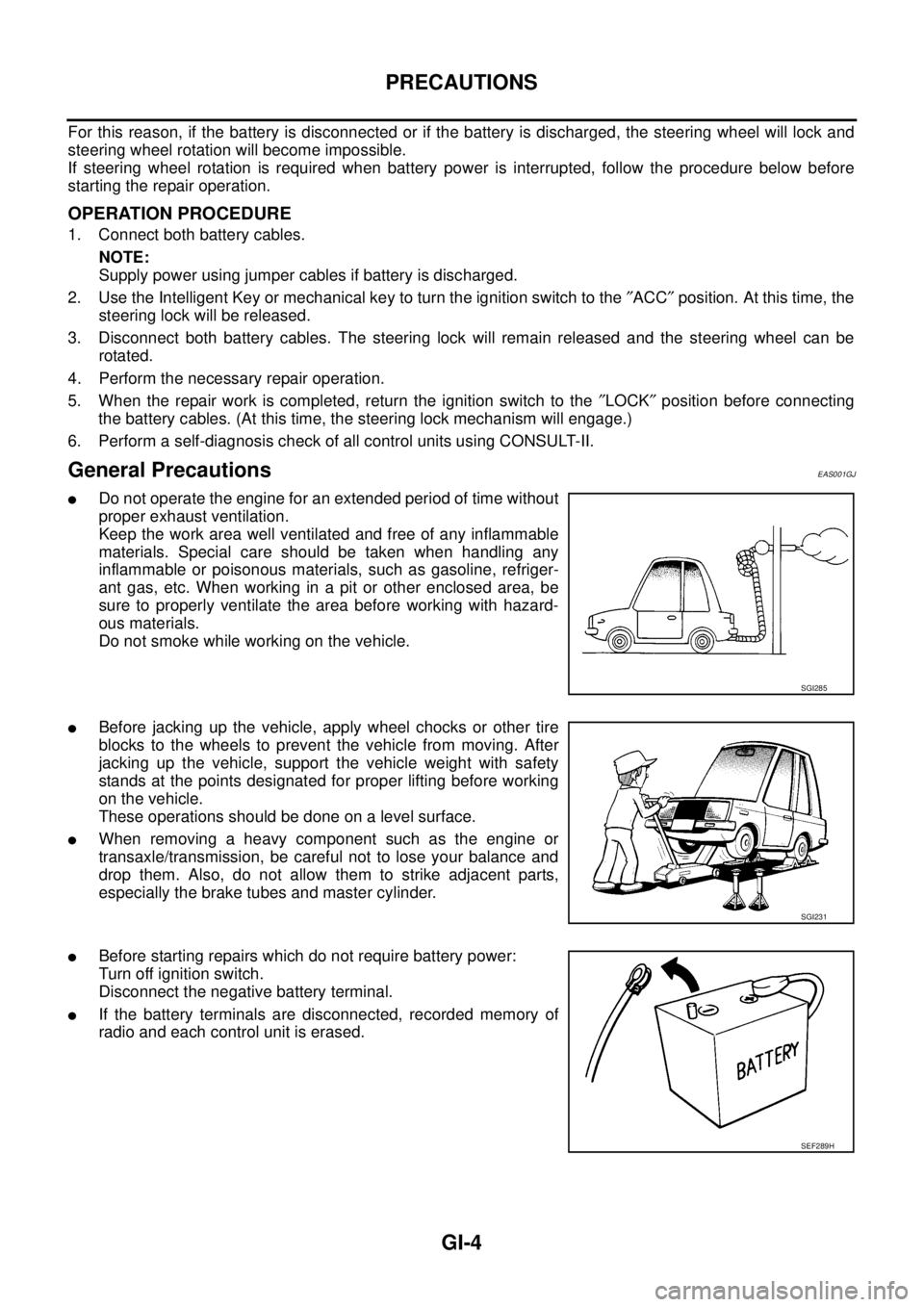
General PrecautionsEAS001GJ
lDo not operate the engine for an extended period of time without
proper exhaust ventilation.
Keep the work area well ventilated and free of any inflammable
materials. Special care should be taken when handling any
inflammable or poisonous materials, such as gasoline, refriger-
ant gas, etc. When working in a pit or other enclosed area, be
sure to properly ventilate the area before working with hazard-
ous materials.
Do not smoke while working on the vehicle.
lBefore jacking up the vehicle, apply wheel chocks or other tire
blocks to the wheels to prevent the vehicle from moving. After
jacking up the vehicle, support the vehicle weight with safety
stands at the points designated for proper lifting before working
on the vehicle.
These operations should be done on a level surface.
lWhen removing a heavy component such as the engine or
transaxle/transmission, be careful not to lose your balance and
drop them. Also, do not allow them to strike adjacent parts,
especially the brake tubes and master cylinder.
lBefore starting repairs which do not require battery power:
Turn off ignition switch.
Disconnect the negative battery terminal.
lIf the battery terminals are disconnected, recorded memory of
radio and each control unit is erased.
SGI285
SGI231
SEF289H
Page 1627 of 3171
PRECAUTIONS
GI-5
C
D
E
F
G
H
I
J
K
L
MB
GI
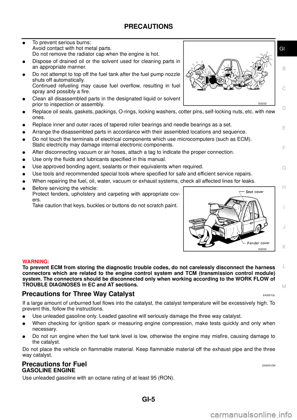
lTo prevent serious burns:
Avoid contact with hot metal parts.
Do not remove the radiator cap when the engine is hot.
lDispose of drained oil or the solvent used for cleaning parts in
an appropriate manner.
lDo not attempt to top off the fuel tank after the fuel pump nozzle
shuts off automatically.
Continued refueling may cause fuel overflow, resulting in fuel
spray and possibly a fire.
lClean all disassembled parts in the designated liquid or solvent
prior to inspection or assembly.
lReplace oil seals, gaskets, packings, O-rings, locking washers, cotter pins, self-locking nuts, etc. with new
ones.
lReplace inner and outer races of tapered roller bearings and needle bearings as a set.
lArrange the disassembled parts in accordance with their assembled locations and sequence.
lDo not touch the terminals of electrical components which use microcomputers (such as ECM).
Static electricity may damage internal electronic components.
lAfter disconnecting vacuum or air hoses, attach a tag to indicate the proper connection.
lUse only the fluids and lubricants specified in this manual.
lUse approved bonding agent, sealants or their equivalents when required.
lUse tools and recommended special tools where specified for safe and efficient service repairs.
lWhen repairing the fuel, oil, water, vacuum or exhaust systems, check all affected lines for leaks.
lBefore servicing the vehicle:
Protect fenders, upholstery and carpeting with appropriate cov-
ers.
Take caution that keys, buckles or buttons do not scratch paint.
WARNING:
To prevent ECM from storing the diagnostic trouble codes, do not carelessly disconnect the harness
connectors which are related to the engine control system and TCM (transmission control module)
system. The connectors should be disconnected only when working according to the WORK FLOW of
TROUBLE DIAGNOSES in EC and AT sections.
Precautions for Three Way CatalystEAS001GL
If a large amount of unburned fuel flows into the catalyst, the catalyst temperature will be excessively high. To
prevent this, follow the instructions.
lUse unleaded gasoline only. Leaded gasoline will seriously damage the three way catalyst.
lWhen checking for ignition spark or measuring engine compression, make tests quickly and only when
necessary.
lDo not run engine when the fuel tank level is low, otherwise the engine may misfire, causing damage to
the catalyst.
Do not place the vehicle on flammable material. Keep flammable material off the exhaust pipe and the three
way catalyst.
Precautions for FuelEAS001GM
GASOLINE ENGINE
Use unleaded gasoline with an octane rating of at least 95 (RON).
SGI233
SGI234
Page 1628 of 3171
GI-6
PRECAUTIONS
CAUTION:
Do not use leaded gasoline. Using leaded gasoline will damage the three way catalyst. Using a fuel
other than that specified could adversely affect the emission control devices and systems, and could
also affect the warranty coverage validity.
DIESEL ENGINE
Diesel fuel of at least 50 cetane.
If two types of diesel fuel are available, use summer or winter fuel properly according to the following temper-
ature conditions.
lAbove –7°C(20°F) ... Summer type diesel fuel.
lBelow –7°C(20°F) ... Winter type diesel fuel.
CAUTION:
lDo not use home heating oil, gasoline or other alternate fuels in your diesel engine. The use of
those can cause engine damage.
lDo not use summer fuel at temperatures below –7°C(20°F). The cold temperatures will cause wax
to form in the fuel. As a result, it may prevent the engine from running smoothly.
lDo not add gasoline or other alternate fuels to diesel fuel.
Precautions for Multiport Fuel Injection System or Engine Control SystemEAS001GN
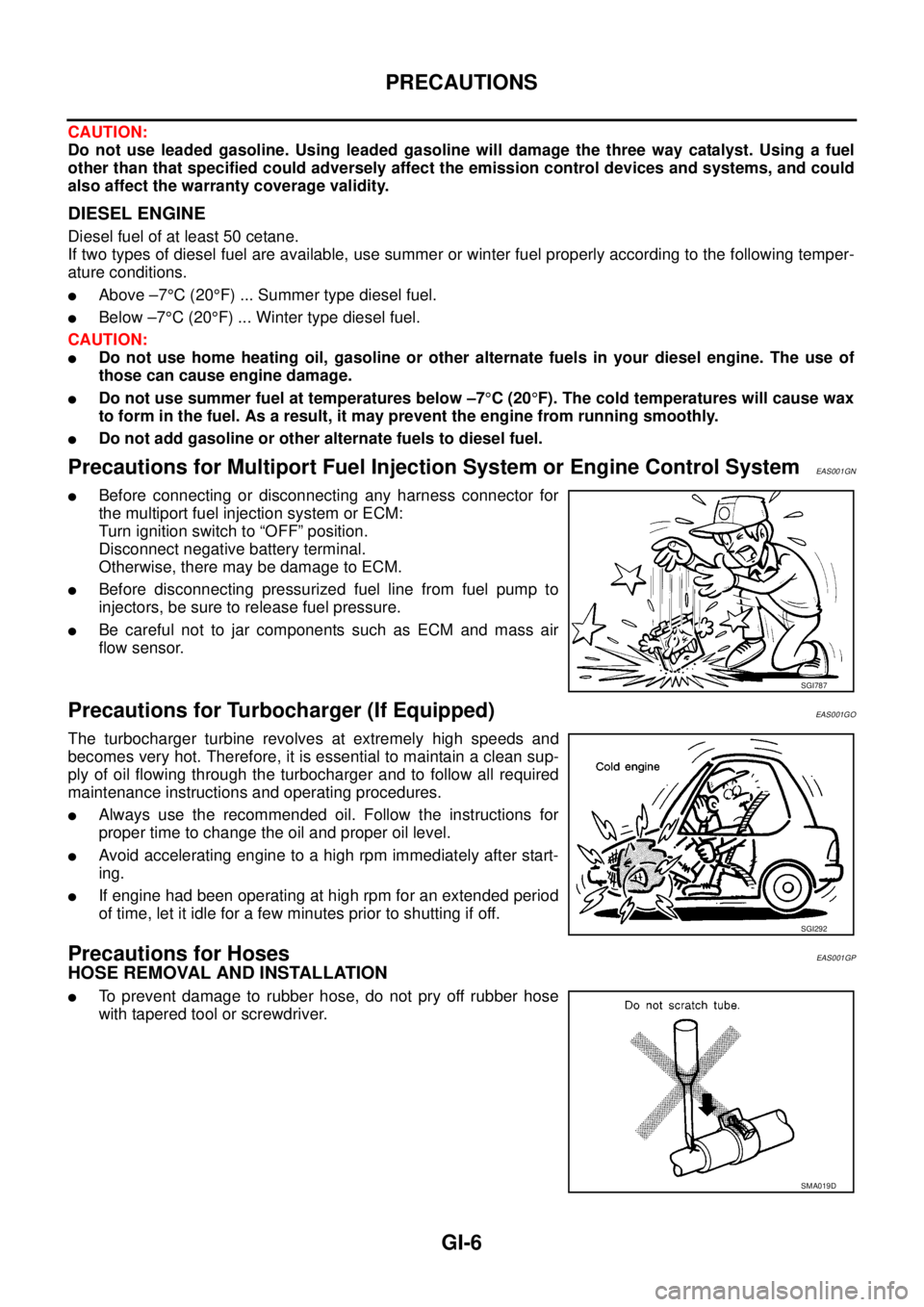
lBefore connecting or disconnecting any harness connector for
the multiport fuel injection system or ECM:
Turn ignition switch to “OFF” position.
Disconnect negative battery terminal.
Otherwise, there may be damage to ECM.
lBefore disconnecting pressurized fuel line from fuel pump to
injectors, be sure to release fuel pressure.
lBe careful not to jar components such as ECM and mass air
flow sensor.
Precautions for Turbocharger (If Equipped)EAS001GO
The turbocharger turbine revolves at extremely high speeds and
becomes very hot. Therefore, it is essential to maintain a clean sup-
ply of oil flowing through the turbocharger and to follow all required
maintenance instructions and operating procedures.
lAlways use the recommended oil. Follow the instructions for
proper time to change the oil and proper oil level.
lAvoid accelerating engine to a high rpm immediately after start-
ing.
lIf engine had been operating at high rpm for an extended period
of time, let it idle for a few minutes prior to shutting if off.
Precautions for HosesEAS001GP
HOSE REMOVAL AND INSTALLATION
lTo prevent damage to rubber hose, do not pry off rubber hose
with tapered tool or screwdriver.
SGI787
SGI292
SMA019D