2005 NISSAN NAVARA control unit
[x] Cancel search: control unitPage 2245 of 3171

LT-162
ILLUMINATION
ILLUMINATION
PFP:27545
System DescriptionEKS00P8V
Control of the illumination lamps operation is dependent upon the position of the lighting switch (combination
switch). When the lighting switch is placed in the 1ST position, 2ND position or AUTO position (headlamp is
ON) the BCM (body control module) receives input signal requesting the illumination lamps to illuminate. This
input signal is communicated to the IPDM E/R (intelligent power distribution module engine room) through the
CAN communication. The CPU (central processing unit) of the IPDM E/R controls the tail lamp relay coil. This
relay, when energized, directs power to the illumination lamps, which then illuminate.
Power is supplied at all times
lto ignition relay (located in IPDM E/R) and
lto tail lamp relay (located in IPDM E/R), from battery directly,
lthrough 50A fusible link (letter G, located in fuse and fusible link box)
lto BCM terminal 57,
lthrough 20A fuse (No. 52, located in IPDM E/R) and
lthrough 20A fuse (No. 53, located in IPDM E/R)
lto CPU (located in IPDM E/R),
lthrough 10A fuse [No.19, located in fuse block (J/B)]
lto combination meter terminal 3.
With the ignition switch in the ON or START position, power is supplied
lto ignition relay (located in IPDM E/R),
lthrough 10A fuse [No. 1, located in fuse block (J/B)]
lto BCM terminal 3,
lthrough 10A fuse [No. 14, located in fuse block (J/B)]
lto combination meter 16.
Ground is supplied
lto BCM terminal 55 and
lto combination meter terminal 23
lthrough grounds M21, M80 and M83,
lto IPDM E/R terminals 38 and 59
lthrough grounds E21, E41 and E61.
ILLUMINATION OPERATION BY LIGHTING SWITCH
With the lighting switch in the 1ST position, 2ND position or AUTO position (headlamp is ON), the BCM
receives input signal requesting the illumination lamps to illuminate. This input signal is communicated to the
IPDM E/R through the CAN communication. The CPU of the IPDM E/R controls the tail lamp relay coil, which,
when energized, directs power
lthrough 10A fuse (No. 37, located in IPDM E/R)
lthrough IPDM E/R terminal 57
lto hazard switch (illumination) terminal 3
lto 4WD shift switch (illumination) terminal 7 (with 4-wheel drive)
lto front air control (illumination) terminal 8
lto audio unit (illumination) terminal 2 (1CD player)
lto audio unit (illumination) terminal 8 (6CD player)
lto AV switch (illumination) terminal 3 (with NAVI)
lto audio unit (illumination) terminal 29 (with NAVI)
lto glove box lamp terminal 1
lto A/T device (illumination) terminal 3 (with A/T)
lto heat up switch (illumination) terminal 5
lto DIFF LOCK switch (illumination) terminal 4 (with DIFF LOCK)
lto heated seat switch (driver side) (illumination) terminal 5 (with heated seats)
lto heated seat switch (passenger side) (illumination) terminal 5 (with heated seats)
Page 2246 of 3171
ILLUMINATION
LT-163
C
D
E
F
G
H
I
J
L
MA
B
LT
lto cigarette lighter (illumination) terminal 1
lto ashtray (illumination) terminal 1
lto headlamp washer switch (illumination) terminal 3
lto headlamp aiming switch (illumination) terminal 3 and
lto NAVI control unit (illumination) terminal 61 (with NAVI).
Ground is supplied
lto hazard switch (illumination) terminal 4
lto 4WD shift switch (illumination) terminal 8 (with 4-wheel drive)
lto front air control (illumination) terminal 9
lto AV switch (illumination) terminal 4 (with NAVI)
lto audio unit (illumination) terminal 28 (with NAVI)
lto DIFF LOCK switch (illumination) terminal 5 (with DIFF LOCK)
lto heated seat switch (driver side) (illumination) terminal 6 (with heated seats) and
lto heated seat switch (passenger side) (illumination) terminal 6 (with heated seats)
lthrough combination meter terminal 22
lthrough combination meter terminal 23
lthrough ground M21, M80 and M83,
lto glove box lamp terminal 2
lto A/T device (illumination) terminal 5 (with A/T)
lto heat up switch (illumination) terminal 6
lto ashtray (illumination) terminal 2
lto headlamp washer switch (illumination) terminal 4 and
lto headlamp aiming switch (illumination) terminal 4
ltrough ground M21, M80 and M83,
lto audio unit (illumination) (1CD and 6CD player)
lthrough case ground of audio unit,
lto cigarette lighter (illumination)
lthrough case ground of cigarette lighter,
lto NAVI control unit (illumination) terminal 1 (with NAVI)
lthrough ground B106 and B121.
With power and ground supplied, illumination lamps illuminate.
CAN Communication System DescriptionEKS00P8W
Refer toLAN-23, "CAN COMMUNICATION".
CAN Communication UnitEKS00P8X
Refer toLAN-30, "CAN Communication Unit".
Page 2295 of 3171
MA-20
ENGINE MAINTENANCE
REFILLING ENGINE COOLANT
1. Install reservoir tank, and radiator drain plug.
CAUTION:
Be sure to clean radiator drain plug and install with new O-ring.
lIf water drain plug on cylinder block is removed, close and tighten it. Refer toEM-110, "CYLIN-
DER BLOCK".
2. Make sure that each hose clamp has been firmly tightened.
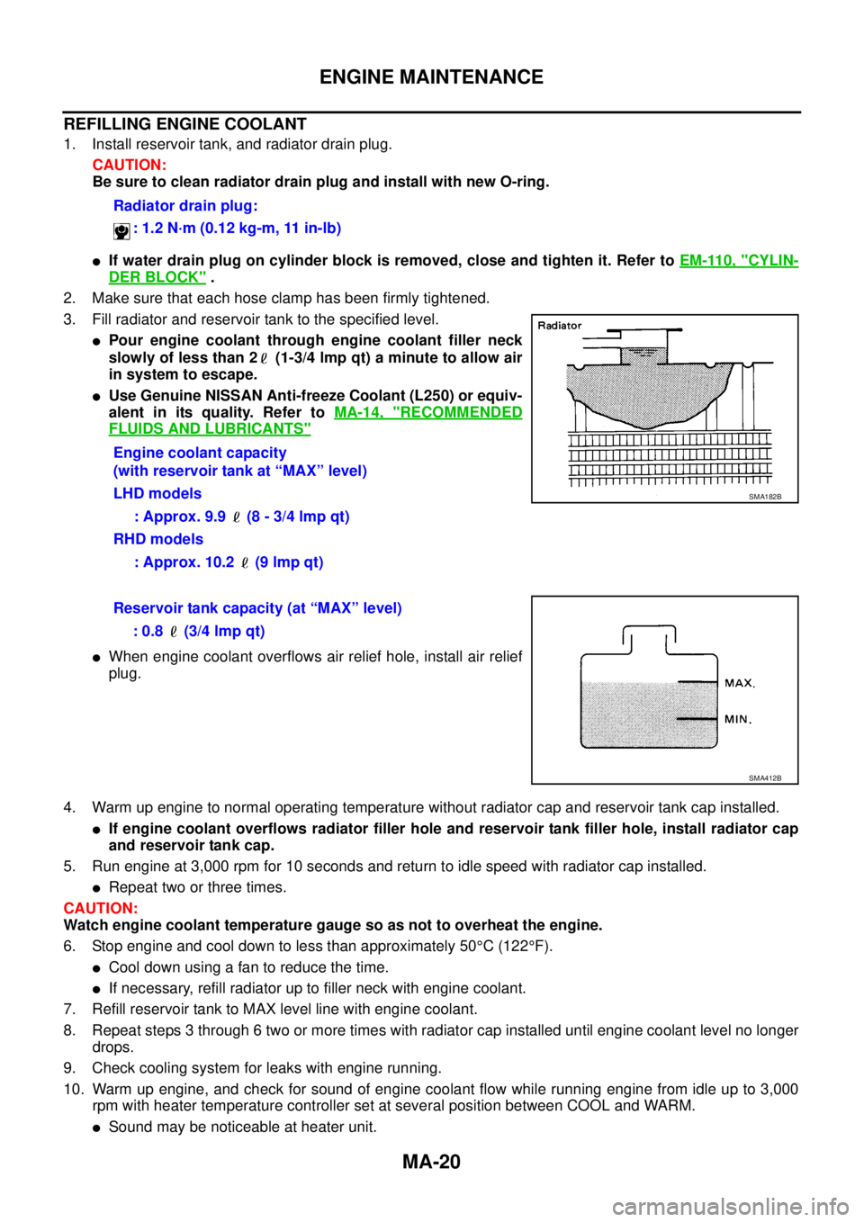
3. Fill radiator and reservoir tank to the specified level.
lPour engine coolant through engine coolant filler neck
slowly of less than 2 (1-3/4 lmp qt) a minute to allow air
in system to escape.
lUse Genuine NISSAN Anti-freeze Coolant (L250) or equiv-
alent in its quality. Refer toMA-14, "
RECOMMENDED
FLUIDS AND LUBRICANTS"
lWhen engine coolant overflows air relief hole, install air relief
plug.
4. Warm up engine to normal operating temperature without radiator cap and reservoir tank cap installed.
lIf engine coolant overflows radiator filler hole and reservoir tank filler hole, install radiator cap
and reservoir tank cap.
5. Run engine at 3,000 rpm for 10 seconds and return to idle speed with radiator cap installed.
lRepeat two or three times.
CAUTION:
Watch engine coolant temperature gauge so as not to overheat the engine.
6. Stop engine and cool down to less than approximately 50°C(122°F).
lCool down using a fan to reduce the time.
lIf necessary, refill radiator up to filler neck with engine coolant.
7. Refill reservoir tank to MAX level line with engine coolant.
8. Repeat steps 3 through 6 two or more times with radiator cap installed until engine coolant level no longer
drops.
9. Check cooling system for leaks with engine running.
10. Warm up engine, and check for sound of engine coolant flow while running engine from idle up to 3,000
rpm with heater temperature controller set at several position between COOL and WARM.
lSound may be noticeable at heater unit.Radiator drain plug:
: 1.2 N·m (0.12 kg-m, 11 in-lb)
Engine coolant capacity
(with reservoir tank at “MAX” level)
LHD models
: Approx. 9.9 (8 - 3/4 lmp qt)
RHD models
: Approx. 10.2 (9 lmp qt)
SMA182B
Reservoir tank capacity (at “MAX” level)
: 0.8 (3/4 lmp qt)
SMA412B
Page 2389 of 3171

MTC-2
Schematic —LHD MODELS— ............................... 38
Wiring Diagram —A/C— —LHD MODELS— ......... 39
Schematic —RHD MODELS— ............................... 44
Wiring Diagram —A/C— —RHD MODELS— ......... 45
Front Air Control Terminals and Reference Value... 49
PIN CONNECTOR TERMINAL LAYOUT ............ 49
TERMINALS AND REFERENCE VALUE FOR
FRONT AIR CONTROL ....................................... 49
A/C System Self-diagnosis Function ...................... 51
DESCRIPTION .................................................... 51
Operational Check .................................................. 53
CHECKING BLOWER ......................................... 53
CHECKING DISCHARGE AIR ............................ 53
CHECKING RECIRCULATION ............................ 53
CHECKING TEMPERATURE DECREASE ......... 54
CHECKING TEMPERATURE INCREASE .......... 54
CHECK A/C SWITCH .......................................... 54
Power Supply and Ground Circuit for Front Air Con-
trol ........................................................................... 55
INSPECTION FLOW ........................................... 55
COMPONENT DESCRIPTION ............................ 56
DIAGNOSTIC PROCEDURE FOR A/C SYSTEM... 56
Mode Door Motor Circuit ........................................ 58
INSPECTION FLOW ........................................... 58
SYSTEM DESCRIPTION .................................... 59
COMPONENT DESCRIPTION ............................ 59
DIAGNOSTIC PROCEDURE FOR MODE
DOOR MOTOR ................................................... 59
Air Mix Door Motor Circuit ...................................... 63
INSPECTION FLOW ........................................... 63
SYSTEM DESCRIPTION .................................... 64
COMPONENT DESCRIPTION ............................ 64
DIAGNOSTIC PROCEDURE FOR AIR MIX
DOOR MOTOR (FRONT) .................................... 64
Intake Door Motor Circuit ........................................ 68
INSPECTION FLOW ........................................... 68
SYSTEM DESCRIPTION .................................... 69
COMPONENT DESCRIPTION ............................ 69
DIAGNOSTIC PROCEDURE FOR INTAKE
DOOR MOTOR ................................................... 69
Blower Motor Circuit ............................................... 71
INSPECTION FLOW ........................................... 71
SYSTEM DESCRIPTION .................................... 72
COMPONENT DESCRIPTION ............................ 72
DIAGNOSTIC PROCEDURE FOR BLOWER
MOTOR ............................................................... 73
COMPONENT INSPECTION .............................. 77
Magnet Clutch Circuit ............................................. 79
INSPECTION FLOW ........................................... 79
SYSTEM DESCRIPTION .................................... 80
DIAGNOSTIC PROCEDURE FOR MAGNET
CLUTCH .............................................................. 80
COMPONENT INSPECTION .............................. 85
Insufficient Cooling ................................................. 86
INSPECTION FLOW ........................................... 86
PERFORMANCE TEST DIAGNOSES ................ 87
PERFORMANCE CHART ................................... 89
TROUBLE DIAGNOSES FOR UNUSUAL PRES-
SURE ................................................................... 90Insufficient Heating ................................................. 93
INSPECTION FLOW ............................................ 93
Noise ....................................................................... 94
INSPECTION FLOW ............................................ 94
Self-diagnosis ......................................................... 95
INSPECTION FLOW ............................................ 95
Intake Sensor Circuit ............................................... 95
COMPONENT DESCRIPTION ............................ 95
DIAGNOSTIC PROCEDURE FOR INTAKE SEN-
SOR ..................................................................... 96
COMPONENT INSPECTION ............................... 97
CONTROL UNIT ........................................................ 98
Removal and Installation ......................................... 98
REMOVAL ............................................................ 98
INSTALLATION .................................................... 98
INTAKE SENSOR ...................................................... 99
Removal and Installation ......................................... 99
REMOVAL ............................................................ 99
INSTALLATION .................................................... 99
BLOWER MOTOR ...................................................100
Components ..........................................................100
Removal and Installation .......................................100
REMOVAL ..........................................................100
INSTALLATION ..................................................100
AIR CONDITIONER FILTER ...................................101
Removal and Installation .......................................101
FUNCTION ........................................................101
REPLACEMENT TIMING ..................................101
REPLACEMENT PROCEDURE ........................101
HEATER & COOLING UNIT ASSEMBLY ...............103
Components ..........................................................103
Removal and Installation .......................................105
REMOVAL ..........................................................105
INSTALLATION ..................................................105
HEATER CORE .......................................................106
Components ..........................................................106
Removal and Installation .......................................107
REMOVAL ..........................................................107
INSTALLATION ..................................................107
DEFROSTER DOOR MOTOR .................................108
Components ..........................................................108
Removal and Installation .......................................108
REMOVAL ..........................................................108
INSTALLATION ..................................................108
INTAKE DOOR MOTOR ..........................................109
Components ..........................................................109
Removal and Installation .......................................109
REMOVAL ..........................................................109
INSTALLATION ..................................................109
MODE DOOR MOTOR ............................................110
Components ..........................................................110
Removal and Installation .......................................110
REMOVAL ..........................................................110
INSTALLATION ..................................................110
AIR MIX DOOR MOTOR ......................................... 111
Components .......................................................... 111
Removal and Installation ....................................... 111
REMOVAL .......................................................... 111
INSTALLATION .................................................. 111
Page 2392 of 3171
PRECAUTIONS
MTC-5
C
D
E
F
G
H
I
K
L
MA
B
MTC
lIf the vehicle is within the warranty period, the air conditioner warranty is void. Please contact NISSAN
Customer Affairs for further assistance.
General Refrigerant PrecautionsEJS00628
WARNING:
lDo not release refrigerant into the air. Use approved recovery/recycling equipment to capture the
refrigerant every time an air conditioning system is discharged.
lAlways wear eye and hand protection (goggles and gloves) when working with any refrigerant or
air conditioning system.
lDo not store or heat refrigerant containers above 52°C.
lDo not heat a refrigerant container with an open flame; if container warming is required, place the
bottom of the container in a warm pail of water.
lDo not intentionally drop, puncture, or incinerate refrigerant containers.
lKeep refrigerant away from open flames: poisonous gas will be produced if refrigerant burns.
lRefrigerant will displace oxygen, therefore be certain to work in well ventilated areas to prevent
suffocation.
lDo not pressure test or leak test HFC-134a (R-134a) service equipment and/or vehicle air condi-
tioning systems with compressed air during repair. Some mixtures of air and HFC-134a (R-134a)
have been shown to be combustible at elevated pressures. These mixtures, if ignited, may cause
injury or property damage. Additional health and safety information may be obtained from refriger-
ant manufacturers.
Precautions for Refrigerant ConnectionEJS005FL
A new type refrigerant connection has been introduced to all refrigerant lines except the following locations.
lExpansion valve to cooling unit
lEvaporator pipes to evaporator (inside cooling unit)
lRefrigerant pressure sensor
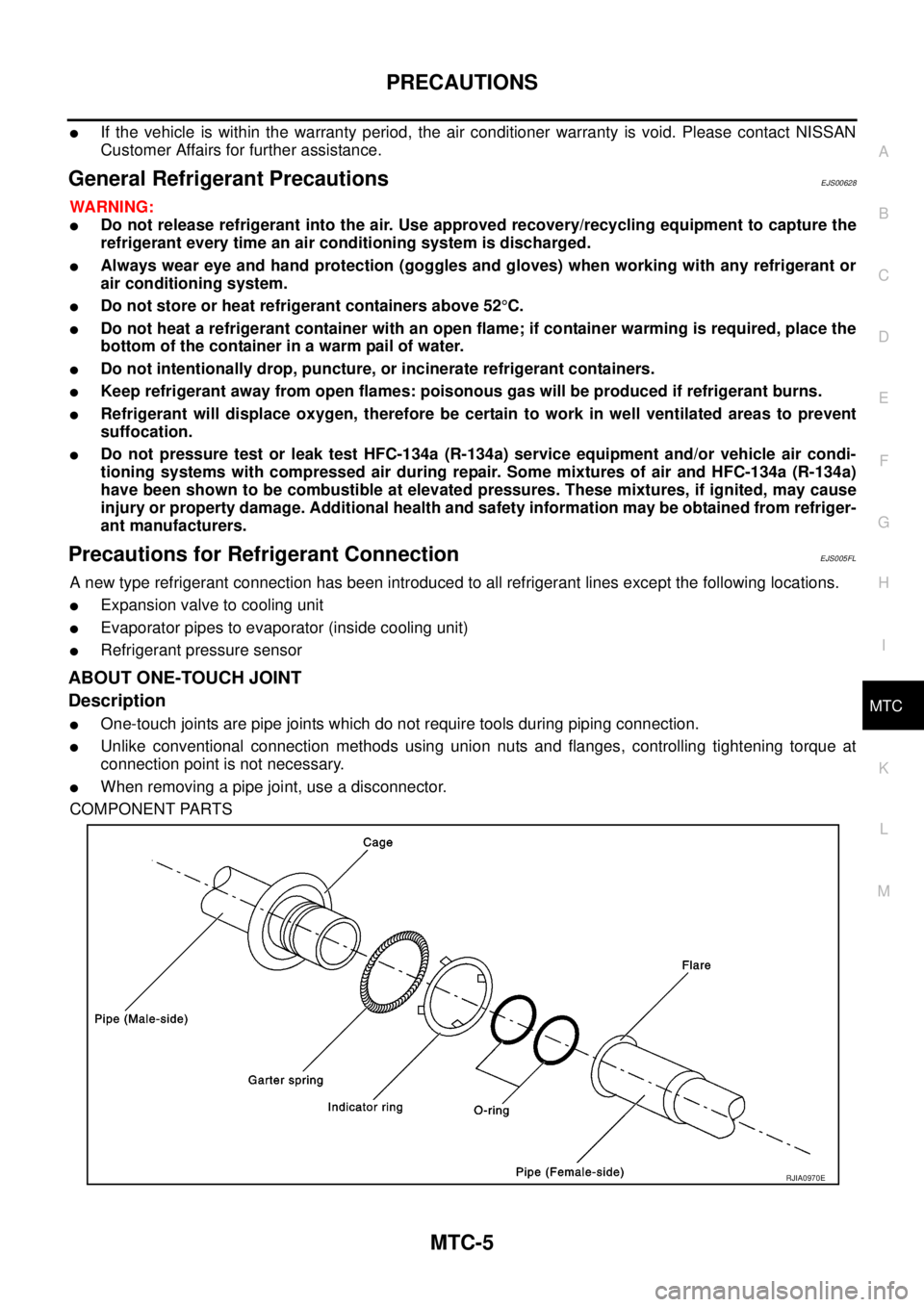
ABOUT ONE-TOUCH JOINT
Description
lOne-touch joints are pipe joints which do not require tools during piping connection.
lUnlike conventional connection methods using union nuts and flanges, controlling tightening torque at
connection point is not necessary.
lWhen removing a pipe joint, use a disconnector.
COMPONENT PARTS
RJIA0970E
Page 2420 of 3171
TROUBLE DIAGNOSIS
MTC-33
C
D
E
F
G
H
I
K
L
MA
B
MTC
TROUBLE DIAGNOSISPFP:00004
CONSULT-IIEJS005G4
CONSULT-II can display each diagnostic item using the diagnostic test modes shown following.
CONSULT-II BASIC OPERATION
CAUTION:
If CONSULT-II is used with no connection of CONSULT-II CONVERTER, malfunctions might be
detected in self-diagnosis depending on control unit which carry out CAN communication.
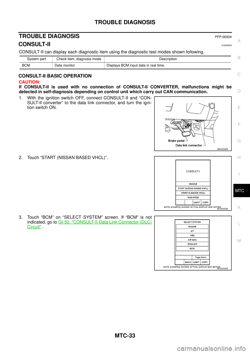
1. With the ignition switch OFF, connect CONSULT-II and “CON-
SULT-II converter” to the data link connector, and turn the igni-
tion switch ON.
2. Touch “START (NISSAN BASED VHCL)”.
3. Touch “BCM” on “SELECT SYSTEM” screen. If “BCM” is not
indicated, go toGI-50, "
CONSULT-II Data Link Connector (DLC)
Circuit".
System part Check item, diagnosis mode Description
BCM Data monitor Displays BCM input data in real time.
BBIA0369E
BCIA0029E
BCIA0030E
Page 2443 of 3171
MTC-56
TROUBLE DIAGNOSIS
COMPONENT DESCRIPTION
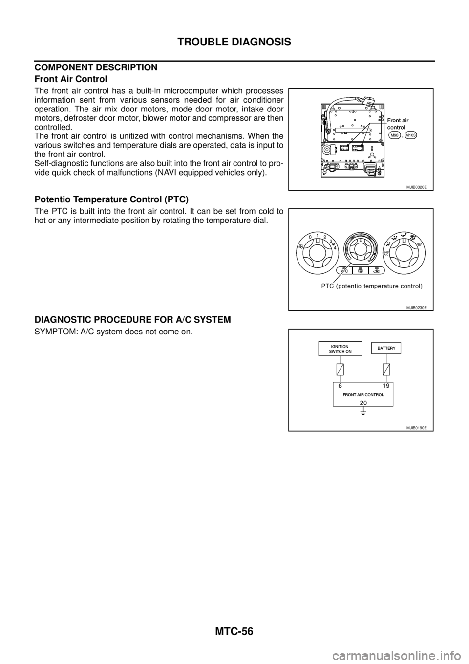
Front Air Control
The front air control has a built-in microcomputer which processes
information sent from various sensors needed for air conditioner
operation. The air mix door motors, mode door motor, intake door
motors, defroster door motor, blower motor and compressor are then
controlled.
The front air control is unitized with control mechanisms. When the
various switches and temperature dials are operated, data is input to
the front air control.
Self-diagnostic functions are also built into the front air control to pro-
vide quick check of malfunctions (NAVI equipped vehicles only).
Potentio Temperature Control (PTC)
The PTC is built into the front air control. It can be set from cold to
hot or any intermediate position by rotating the temperature dial.
DIAGNOSTIC PROCEDURE FOR A/C SYSTEM
SYMPTOM: A/C system does not come on.
MJIB0320E
MJIB0230E
MJIB0190E
Page 2444 of 3171
TROUBLE DIAGNOSIS
MTC-57
C
D
E
F
G
H
I
K
L
MA
B
MTC
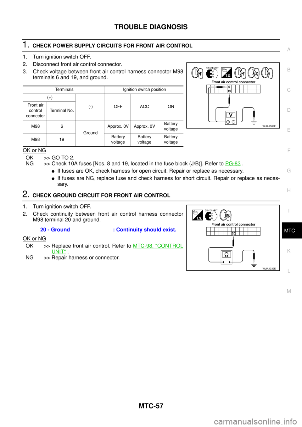
1.CHECK POWER SUPPLY CIRCUITS FOR FRONT AIR CONTROL
1. Turn ignition switch OFF.
2. Disconnect front air control connector.
3. Check voltage between front air control harness connector M98
terminals 6 and 19, and ground.
OK or NG
OK >> GO TO 2.
NG >> Check 10A fuses [Nos. 8 and 19, located in the fuse block (J/B)]. Refer toPG-83
.
lIf fuses are OK, check harness for open circuit. Repair or replace as necessary.
lIf fuses are NG, replace fuse and check harness for short circuit. Repair or replace as neces-
sary.
2.CHECK GROUND CIRCUIT FOR FRONT AIR CONTROL
1. Turn ignition switch OFF.
2. Check continuity between front air control harness connector
M98 terminal 20 and ground.
OK or NG
OK >> Replace front air control. Refer toMTC-98, "CONTROL
UNIT".
NG >> Repair harness or connector.
Terminals Ignition switch position
(+)
(-) OFF ACC ON Front air
control
connectorTerminal No.
M98 6
GroundApprox. 0V Approx. 0VBattery
voltage
M98 19Battery
voltageBattery
voltageBattery
voltage
WJIA1082E
20 - Ground : Continuity should exist.
WJIA1239E