Page 2154 of 3171

FRONT FOG LAMP
LT-71
C
D
E
F
G
H
I
J
L
MA
B
LT
FRONT FOG LAMPPFP:26150
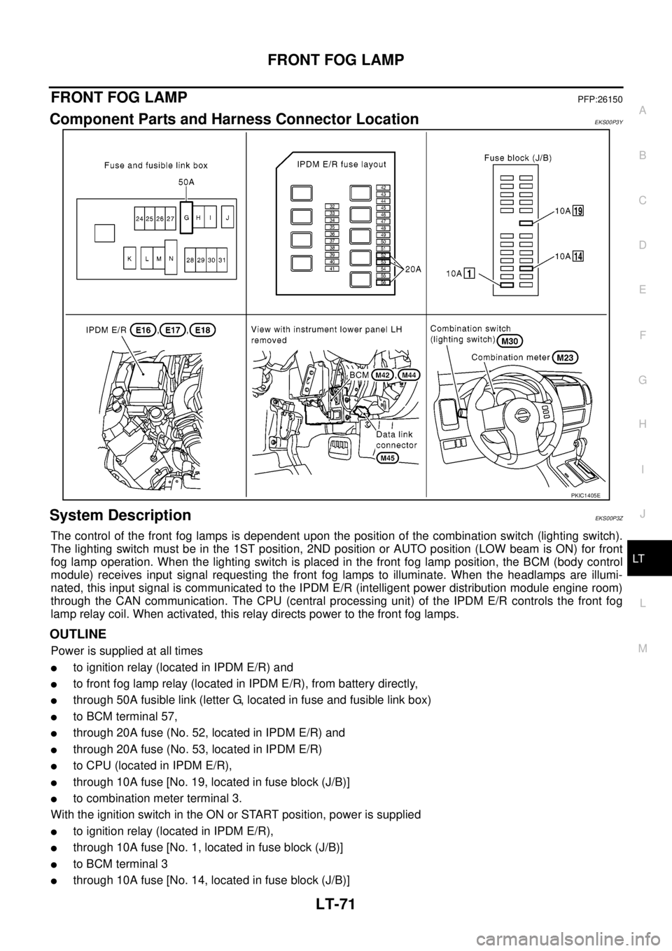
Component Parts and Harness Connector LocationEKS00P3Y
System DescriptionEKS00P3Z
The control of the front fog lamps is dependent upon the position of the combination switch (lighting switch).
The lighting switch must be in the 1ST position, 2ND position or AUTO position (LOW beam is ON) for front
fog lamp operation. When the lighting switch is placed in the front fog lamp position, the BCM (body control
module) receives input signal requesting the front fog lamps to illuminate. When the headlamps are illumi-
nated, this input signal is communicated to the IPDM E/R (intelligent power distribution module engine room)
through the CAN communication. The CPU (central processing unit) of the IPDM E/R controls the front fog
lamp relay coil. When activated, this relay directs power to the front fog lamps.
OUTLINE
Power is supplied at all times
lto ignition relay (located in IPDM E/R) and
lto front fog lamp relay (located in IPDM E/R), from battery directly,
lthrough 50A fusible link (letter G, located in fuse and fusible link box)
lto BCM terminal 57,
lthrough 20A fuse (No. 52, located in IPDM E/R) and
lthrough 20A fuse (No. 53, located in IPDM E/R)
lto CPU (located in IPDM E/R),
lthrough 10A fuse [No. 19, located in fuse block (J/B)]
lto combination meter terminal 3.
With the ignition switch in the ON or START position, power is supplied
lto ignition relay (located in IPDM E/R),
lthrough 10A fuse [No. 1, located in fuse block (J/B)]
lto BCM terminal 3
lthrough 10A fuse [No. 14, located in fuse block (J/B)]
PKIC1405E
Page 2181 of 3171

LT-98
TURN SIGNAL AND HAZARD WARNING LAMPS
lto side turn signal lamp LH terminal 1 and
lto rear combination lamp LH terminal 2.
Ground is supplied
lto front combination lamp LH terminal 2
lto side turn signal lamp LH terminal 2 and
lto rear combination lamp LH terminal 3
lthrough ground E21, E41 and E61.
The BCM also supplies input to combination meter terminals 11 and 12 through the CAN communication. This
input is processed by unified meter control unit in combination meter, which in turn supplies ground to the left
turn signal indicator lamp.
With power and input supplied, BCM controls flashing of LH turn signal lamps.
RH Turn
When the turn signal switch is moved to the right position, BCM receives input signal requesting right turn sig-
nals to flash.
BCM then supplies power
lthrough BCM terminal 48
lto front combination lamp RH terminal 1
lto side turn signal lamp RH terminal 1 and
lto rear combination lamp RH terminal 2.
Ground is supplied
lto front combination lamp RH terminal 2
lto side turn signal lamp RH terminal 2 and
lto rear combination lamp RH terminal 3
lthrough ground E21, E41 and E61.
The BCM also supplies input to combination meter terminals 11 and 12 through the CAN communication. This
input is processed by unified meter control unit in combination meter, which in turn supplies ground to the right
turn signal indicator lamp.
With power and input supplied, BCM controls flashing of RH turn signal lamps.
HAZARD LAMP OPERATION
Power is supplied at all times
lthrough 50A fusible link (letter G, located in fuse and fusible link box)
lto BCM terminal 57,
lthrough 10A fuse [No. 19, located in fuse block (J/B)]
lto combination meter terminal 3.
Ground is supplied
lto BCM terminal 55 and
lto combination meter terminal 23
lthrough grounds M21, M80 and M83.
When the hazard switch is depressed, ground is supplied
lto BCM terminal 33
lthrough hazard switch terminal 2
lthrough hazard switch terminal 1
lthrough grounds M21, M80 and M83.
When the hazard switch is depressed, BCM receives input signal requesting turn signals to flash.
BCM then supplies power
lthrough BCM terminal 47
lto front combination lamp LH terminal 1
lto side turn signal lamp LH terminal 1 and
lto rear combination lamp LH terminal 2,
lthrough BCM terminal 48
Page 2182 of 3171

TURN SIGNAL AND HAZARD WARNING LAMPS
LT-99
C
D
E
F
G
H
I
J
L
MA
B
LT
lto front combination lamp RH terminal 1
lto side turn signal lamp RH terminal 1 and
lto rear combination lamp RH terminal 2.
Ground is supplied
lto front combination lamp RH and LH terminals 2
lto side turn signal lamp RH and LH terminals 2 and
lto rear combination lamp RH and LH terminals 3
lthrough ground E21, E41 and E61.
The BCM also supplies input to combination meter terminals 11 and 12 through the CAN communication. This
input is processed by unified meter control unit in combination meter, which in turn supplies ground to the left
and right turn signal indicator lamps.
With power and input supplied, BCM controls flashing of hazard warning lamps.
REMOTE KEYLESS ENTRY SYSTEM OPERATION
Refer toBL-89, "MULTI-REMOTE CONTROL SYSTEM".
COMBINATION SWITCH READING FUNCTION
Refer toBCS-3, "COMBINATION SWITCH READING FUNCTION".
CAN Communication System DescriptionEKS00P87
Refer toLAN-23, "CAN COMMUNICATION".
Page 2188 of 3171
TURN SIGNAL AND HAZARD WARNING LAMPS
LT-105
C
D
E
F
G
H
I
J
L
MA
B
LT
CONSULT-II Function (BCM)EKS00P8C
CONSULT-II can display each diagnostic item using the diagnostic test mode shown following.
CONSULT-II OPERATION
CAUTION:
If CONSULT-II is used with no connection of CONSULT-II CONVERTER, malfunctions might be
detected in self-diagnosis depending on control unit which carries out CAN communication.
1. With the ignition switch OFF, connect CONSULT-II and CON-
SULT-II CONVERTER to the data link connector, and then turn
ignition switch ON.
2. Touch “START (NISSAN BASED VHCL)”.
3. Touch “BCM” on “SELECT SYSTEM” screen.
If “BCM” is not indicated, refer toGI-50, "
CONSULT-II Data Link
Connector (DLC) Circuit".
BCM diagnostic
partDiagnostic mode Description
FLASHERDATA MONITOR Displays BCM input/output data in real time.
ACTIVE TEST Operation of electrical loads can be checked by sending drive signal to them.
BBIA0538E
BCIA0029E
BCIA0030E
Page 2198 of 3171
COMBINATION SWITCH
LT-115
C
D
E
F
G
H
I
J
L
MA
B
LT
Combination Switch Reading FunctionEKS00P9W
Refer toBCS-3, "COMBINATION SWITCH READING FUNCTION".
CONSULT-II Function (BCM)EKS00P9X
CONSULT-II can display each diagnostic item using the diagnostic test mode shown following.
CONSULT-II OPERATION
CAUTION:
If CONSULT-II is used with no connection of CONSULT-II CONVERTER, malfunctions might be
detected in self-diagnosis depending on control unit which carries out CAN communication.
1. With the ignition switch OFF, connect CONSULT-II and CON-
SULT-II CONVERTER to the data link connector, and then turn
ignition switch ON.
2. Touch “START (NISSAN BASED VHCL)”.
3. Touch “BCM” on “SELECT SYSTEM” screen.
If “BCM” is not indicated, refer toGI-50, "
CONSULT-II Data Link
Connector (DLC) Circuit".
BCM diagnostic part Diagnostic mode Description
COMBINATION SWITCH DATA MONITOR Displays BCM input/output data in real time.
BBIA0538E
BCIA0029E
BCIA0030E
Page 2201 of 3171

LT-118
COMBINATION SWITCH
Combination Switch Inspection
EKS00P9Y
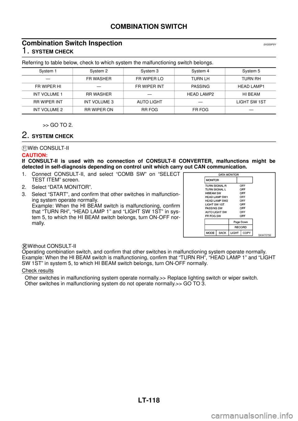
1.SYSTEM CHECK
Referring to table below, check to which system the malfunctioning switch belongs.
>> GO TO 2.
2.SYSTEM CHECK
With CONSULT-II
CAUTION:
If CONSULT-II is used with no connection of CONSULT-II CONVERTER, malfunctions might be
detected in self-diagnosis depending on control unit which carry out CAN communication.
1. Connect CONSULT-II, and select “COMB SW” on “SELECT
TEST ITEM” screen.
2. Select “DATA MONITOR”.
3. Select “START”, and confirm that other switches in malfunction-
ing system operate normally.
Example: When the HI BEAM switch is malfunctioning, confirm
that “TURN RH”, “HEAD LAMP 1” and “LIGHT SW 1ST” in sys-
tem 5, to which the HI BEAM switch belongs, turn ON-OFF nor-
mally.
Without CONSULT-II
Operating combination switch, and confirm that other switches in malfunctioning system operate normally.
Example: When the HI BEAM switch is malfunctioning, confirm that “TURN RH”, “HEAD LAMP 1” and “LIGHT
SW 1ST” in system 5, to which HI BEAM switch belongs, turn ON-OFF normally.
Check results
Other switches in malfunctioning system operate normally.>> Replace lighting switch or wiper switch.
Other switches in malfunctioning system do not operate normally.>> GO TO 3.
System 1 System 2 System 3 System 4 System 5
— FR WASHER FR WIPER LO TURN LH TURN RH
FR WIPER HI — FR WIPER INT PASSING HEAD LAMP1
INT VOLUME 1 RR WASHER — HEAD LAMP2 HI BEAM
RR WIPER INT INT VOLUME 3 AUTO LIGHT — LIGHT SW 1ST
INT VOLUME 2 RR WIPER ON RR FOG FR FOG —
SKIA7075E
Page 2208 of 3171

PARKING, LICENSE PLATE AND TAIL LAMPS
LT-125
C
D
E
F
G
H
I
J
L
MA
B
LT
PARKING, LICENSE PLATE AND TAIL LAMPSPFP:26550
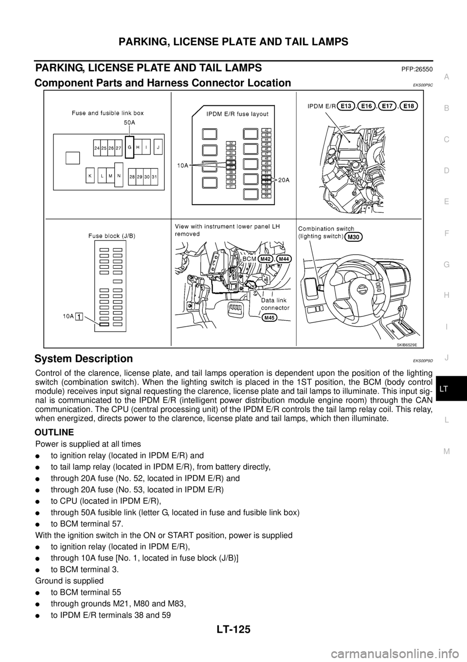
Component Parts and Harness Connector LocationEKS00P9C
System DescriptionEKS00P9D
Control of the clarence, license plate, and tail lamps operation is dependent upon the position of the lighting
switch (combination switch). When the lighting switch is placed in the 1ST position, the BCM (body control
module) receives input signal requesting the clarence, license plate and tail lamps to illuminate. This input sig-
nal is communicated to the IPDM E/R (intelligent power distribution module engine room) through the CAN
communication. The CPU (central processing unit) of the IPDM E/R controls the tail lamp relay coil. This relay,
when energized, directs power to the clarence, license plate and tail lamps, which then illuminate.
OUTLINE
Power is supplied at all times
lto ignition relay (located in IPDM E/R) and
lto tail lamp relay (located in IPDM E/R), from battery directly,
lthrough 20A fuse (No. 52, located in IPDM E/R) and
lthrough 20A fuse (No. 53, located in IPDM E/R)
lto CPU (located in IPDM E/R),
lthrough 50A fusible link (letter G, located in fuse and fusible link box)
lto BCM terminal 57.
With the ignition switch in the ON or START position, power is supplied
lto ignition relay (located in IPDM E/R),
lthrough 10A fuse [No. 1, located in fuse block (J/B)]
lto BCM terminal 3.
Ground is supplied
lto BCM terminal 55
lthrough grounds M21, M80 and M83,
lto IPDM E/R terminals 38 and 59
SKIB6529E
Page 2240 of 3171
INTERIOR ROOM LAMP
LT-157
C
D
E
F
G
H
I
J
L
MA
B
LT
CONSULT-II FunctionEKS00P99
CONSULT-II can display each diagnostic item using the diagnostic test mode shown following.
CONSULT-II OPERATION
CAUTION:
If CONSULT-II is used with no connection of CONSULT-II CONVERTER, malfunctions might be
detected in self-diagnosis depending on control unit which carries out CAN communication.
1. With the ignition switch OFF, connect CONSULT-II and CON-
SULT-II CONVERTER to the data link connector, and then turn
ignition switch ON.
2. Touch “START (NISSAN BASED VHCL)”.
3. Touch “BCM” on “SELECT SYSTEM” screen.
If “BCM” is not indicated, refer toGI-50, "
CONSULT-II Data Link
Connector (DLC) Circuit".
BCM diagnosis part Diagnosis mode Description
INT LAMPWORK SUPPORT Changes the setting for each function.
DATA MONITOR Displays BCM input data in real time.
ACTIVE TEST Operation of electrical loads can be checked by sending drive signal to them.
BBIA0538E
BCIA0029E
BCIA0030E