Page 2088 of 3171
HEADLAMP -CONVENTIONAL TYPE-
LT-5
C
D
E
F
G
H
I
J
L
MA
B
LT
HEADLAMP -CONVENTIONAL TYPE-PFP:26010
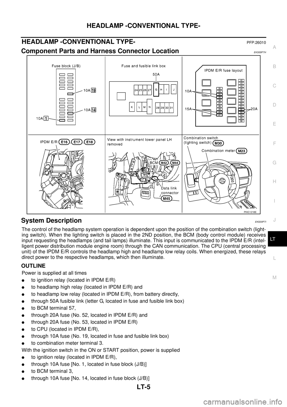
Component Parts and Harness Connector LocationEKS00P7H
System DescriptionEKS00P7I
The control of the headlamp system operation is dependent upon the position of the combination switch (light-
ing switch). When the lighting switch is placed in the 2ND position, the BCM (body control module) receives
input requesting the headlamps (and tail lamps) illuminate. This input is communicated to the IPDM E/R (intel-
ligent power distribution module engine room) through the CAN communication. The CPU (central processing
unit) of the IPDM E/R controls the headlamp high and headlamp low relay coils. When energized, these relays
direct power to the respective headlamps, which then illuminate.
OUTLINE
Power is supplied at all times
lto ignition relay (located in IPDM E/R)
lto headlamp high relay (located in IPDM E/R) and
lto headlamp low relay (located in IPDM E/R), from battery directly,
lthrough 50A fusible link (letter G, located in fuse and fusible link box)
lto BCM terminal 57,
lthrough 20A fuse (No. 52, located in IPDM E/R) and
lthrough 20A fuse (No. 53, located in IPDM E/R)
lto CPU (located in IPDM E/R),
lthrough 10A fuse (No. 19, located in fuse and fusible link box)
lto combination meter terminal 3.
With the ignition switch in the ON or START position, power is supplied
lto ignition relay (located in IPDM E/R),
lthrough 10A fuse [No. 1, located in fuse block (J/B)]
lto BCM terminal 3,
lthrough 10A fuse [No. 14, located in fuse block (J/B)]
PKIC1218E
Page 2098 of 3171
HEADLAMP -CONVENTIONAL TYPE-
LT-15
C
D
E
F
G
H
I
J
L
MA
B
LT
CONSULT-II Functions (BCM)EKS00P7Q
CONSULT-II can display each diagnostic item using the diagnostic test modes shown following.
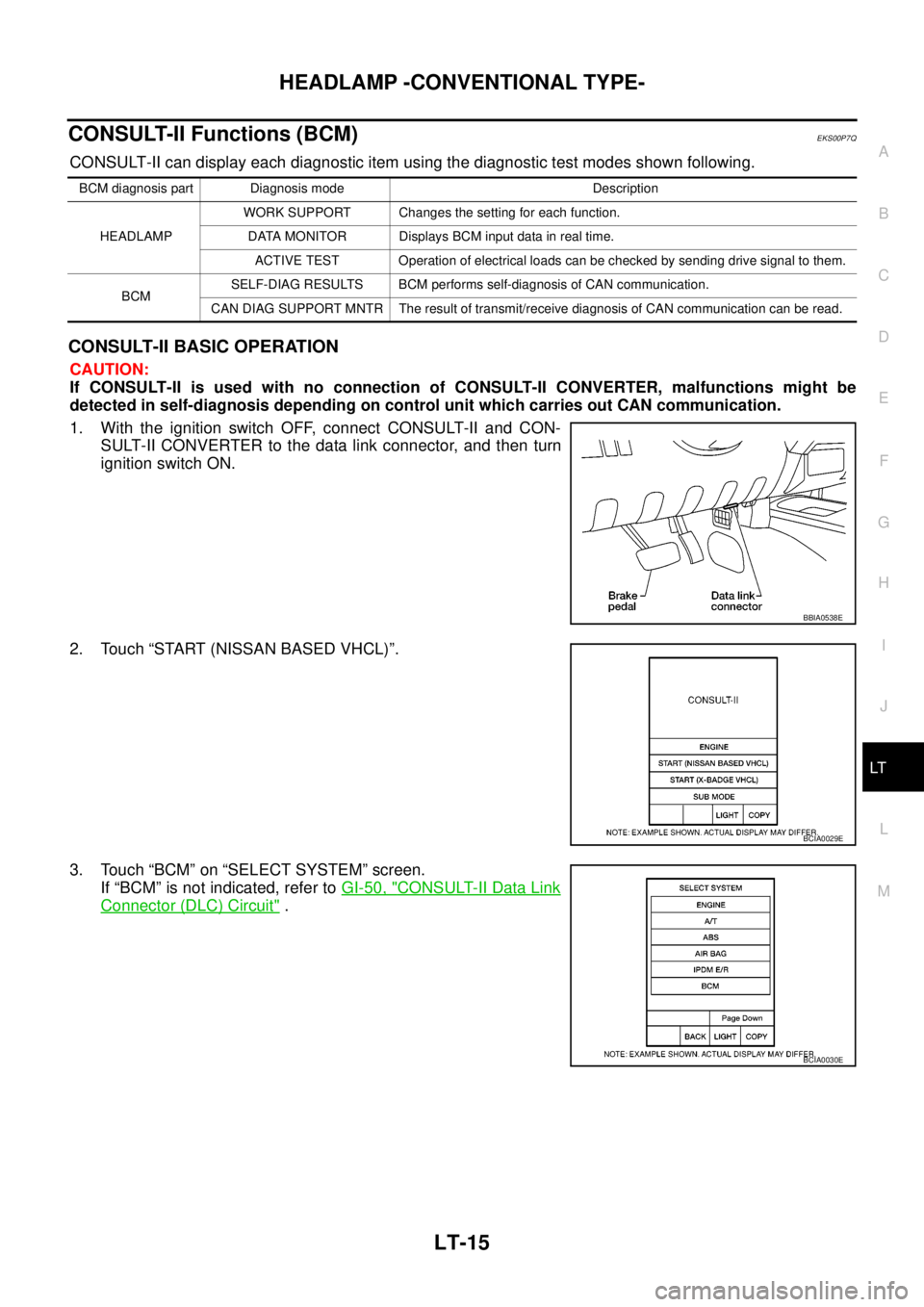
CONSULT-II BASIC OPERATION
CAUTION:
If CONSULT-II is used with no connection of CONSULT-II CONVERTER, malfunctions might be
detected in self-diagnosis depending on control unit which carries out CAN communication.
1. With the ignition switch OFF, connect CONSULT-II and CON-
SULT-II CONVERTER to the data link connector, and then turn
ignition switch ON.
2. Touch “START (NISSAN BASED VHCL)”.
3. Touch “BCM” on “SELECT SYSTEM” screen.
If “BCM” is not indicated, refer toGI-50, "
CONSULT-II Data Link
Connector (DLC) Circuit".
BCM diagnosis part Diagnosis mode Description
HEADLAMPWORK SUPPORT Changes the setting for each function.
DATA MONITOR Displays BCM input data in real time.
ACTIVE TEST Operation of electrical loads can be checked by sending drive signal to them.
BCMSELF-DIAG RESULTS BCM performs self-diagnosis of CAN communication.
CAN DIAG SUPPORT MNTR The result of transmit/receive diagnosis of CAN communication can be read.
BBIA0538E
BCIA0029E
BCIA0030E
Page 2101 of 3171
LT-18
HEADLAMP -CONVENTIONAL TYPE-
CONSULT-II Functions (IPDM E/R)
EKS00P7R
CONSULT-II can display each diagnostic item using the diagnostic test modes shown following.
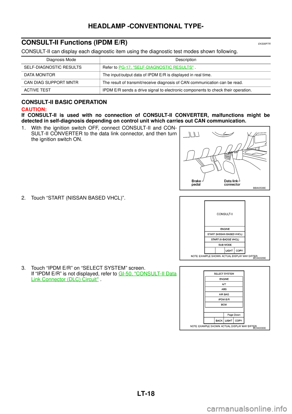
CONSULT-II BASIC OPERATION
CAUTION:
If CONSULT-II is used with no connection of CONSULT-II CONVERTER, malfunctions might be
detected in self-diagnosis depending on control unit which carries out CAN communication.
1. With the ignition switch OFF, connect CONSULT-II and CON-
SULT-II CONVERTER to the data link connector, and then turn
the ignition switch ON.
2. Touch “START (NISSAN BASED VHCL)”.
3. Touch “IPDM E/R” on “SELECT SYSTEM” screen.
If “IPDM E/R” is not displayed, refer toGI-50, "
CONSULT-II Data
Link Connector (DLC) Circuit".
Diagnosis Mode Description
SELF-DIAGNOSTIC RESULTS Refer toPG-17, "
SELF-DIAGNOSTIC RESULTS".
DATA MONITOR The input/output data of IPDM E/R is displayed in real time.
CAN DIAG SUPPORT MNTR The result of transmit/receive diagnosis of CAN communication can be read.
ACTIVE TEST IPDM E/R sends a drive signal to electronic components to check their operation.
BBIA0538E
BCIA0029E
BCIA0030E
Page 2114 of 3171
HEADLAMP - DAYTIME LIGHT SYSTEM -
LT-31
C
D
E
F
G
H
I
J
L
MA
B
LT
HEADLAMP - DAYTIME LIGHT SYSTEM -PFP:26010
Component Parts and Harness Connector LocationEKS00Q7E
System DescriptionEKS00Q7F
The daytime light system is to illuminate headlamp low beam, clearance lamps, tail lamps and license plate
lamps while the engine is running.
When the engine is running, the BCM (body control module) receives the engine status signal. Then the BCM
sends the headlamp low beam request signal and the daytime light request signal to the IPDM E/R (intelligent
power distribution module engine room) through the CAN communication. As the IPDM E/R receives the
above request signals, its CPU (central processing unit) controls headlamp low relay to illuminate headlamp
low beam, clearance lamps, tail lamps and license plate lamps.
PKIC1219E
Page 2125 of 3171
LT-42
HEADLAMP - DAYTIME LIGHT SYSTEM -
CONSULT-II Functions (BCM)
EKS00Q7O
CONSULT-II can display each diagnostic item using the diagnostic test mode shown following.
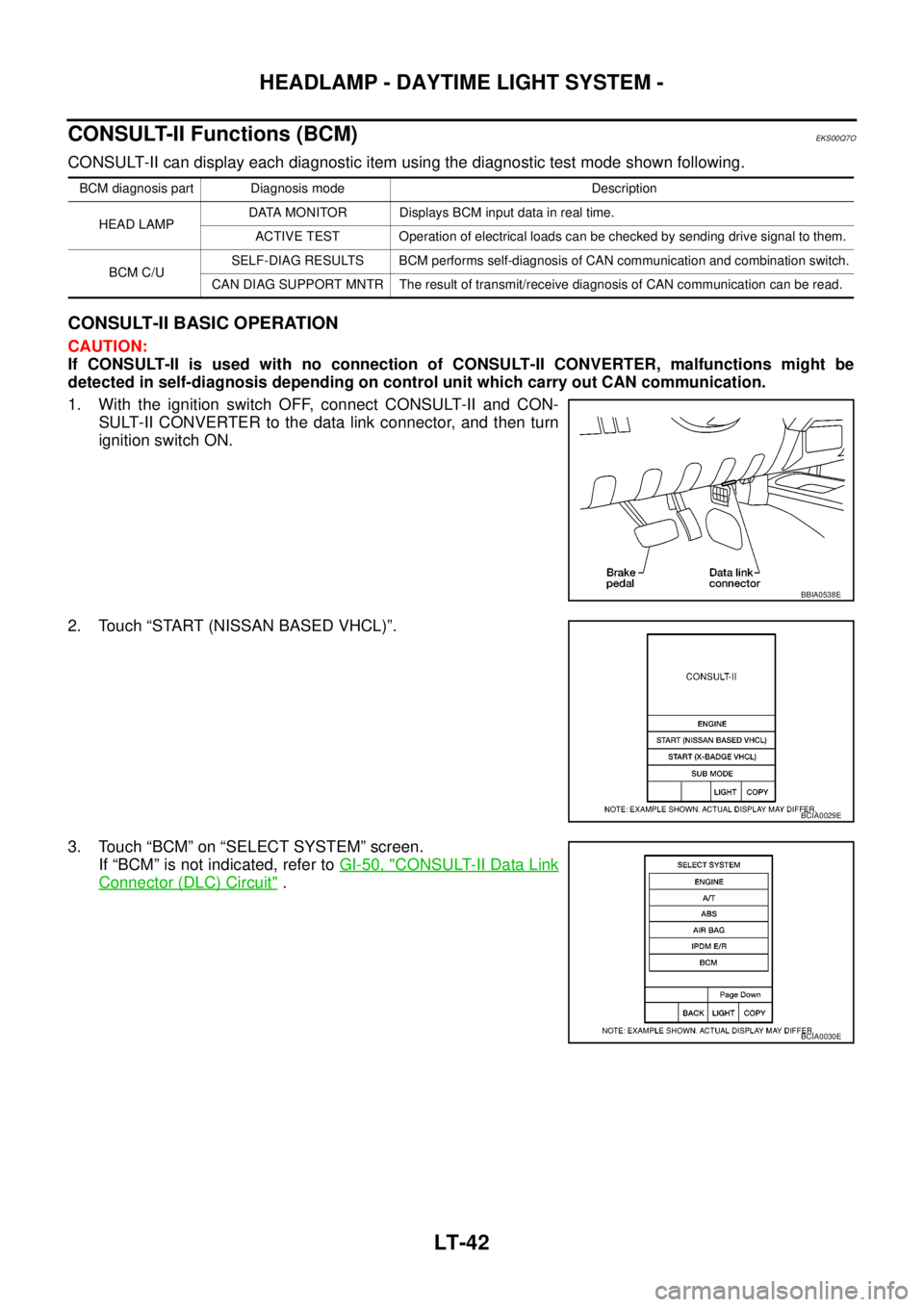
CONSULT-II BASIC OPERATION
CAUTION:
If CONSULT-II is used with no connection of CONSULT-II CONVERTER, malfunctions might be
detected in self-diagnosis depending on control unit which carry out CAN communication.
1. With the ignition switch OFF, connect CONSULT-II and CON-
SULT-II CONVERTER to the data link connector, and then turn
ignition switch ON.
2. Touch “START (NISSAN BASED VHCL)”.
3. Touch “BCM” on “SELECT SYSTEM” screen.
If “BCM” is not indicated, refer toGI-50, "
CONSULT-II Data Link
Connector (DLC) Circuit".
BCM diagnosis part Diagnosis mode Description
HEAD LAMPDATA MONITOR Displays BCM input data in real time.
ACTIVE TEST Operation of electrical loads can be checked by sending drive signal to them.
BCM C/USELF-DIAG RESULTS BCM performs self-diagnosis of CAN communication and combination switch.
CAN DIAG SUPPORT MNTR The result of transmit/receive diagnosis of CAN communication can be read.
BBIA0538E
BCIA0029E
BCIA0030E
Page 2128 of 3171
HEADLAMP - DAYTIME LIGHT SYSTEM -
LT-45
C
D
E
F
G
H
I
J
L
MA
B
LT
CONSULT-II Functions (IPDM E/R)EKS00Q7P
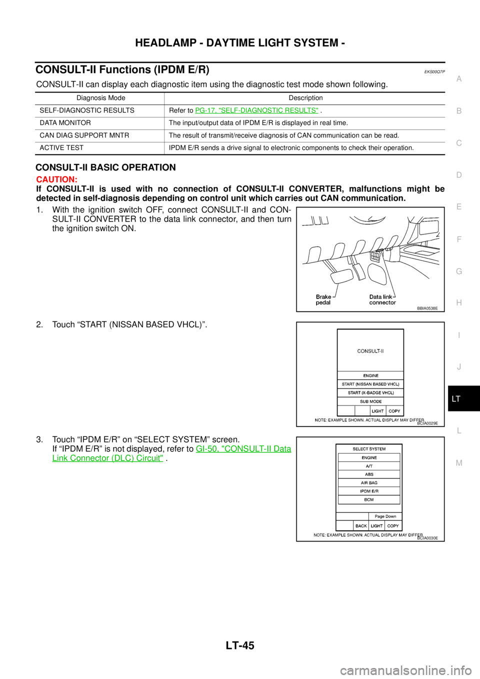
CONSULT-II can display each diagnostic item using the diagnostic test mode shown following.
CONSULT-II BASIC OPERATION
CAUTION:
If CONSULT-II is used with no connection of CONSULT-II CONVERTER, malfunctions might be
detected in self-diagnosis depending on control unit which carries out CAN communication.
1. With the ignition switch OFF, connect CONSULT-II and CON-
SULT-II CONVERTER to the data link connector, and then turn
theignitionswitchON.
2. Touch “START (NISSAN BASED VHCL)”.
3. Touch “IPDM E/R” on “SELECT SYSTEM” screen.
If “IPDM E/R” is not displayed, refer toGI-50, "
CONSULT-II Data
Link Connector (DLC) Circuit".
Diagnosis Mode Description
SELF-DIAGNOSTIC RESULTS Refer toPG-17, "
SELF-DIAGNOSTIC RESULTS".
DATA MONITOR The input/output data of IPDM E/R is displayed in real time.
CAN DIAG SUPPORT MNTR The result of transmit/receive diagnosis of CAN communication can be read.
ACTIVE TEST IPDM E/R sends a drive signal to electronic components to check their operation.
BBIA0538E
BCIA0029E
BCIA0030E
Page 2142 of 3171
AUTO LIGHT SYSTEM
LT-59
C
D
E
F
G
H
I
J
L
MA
B
LT
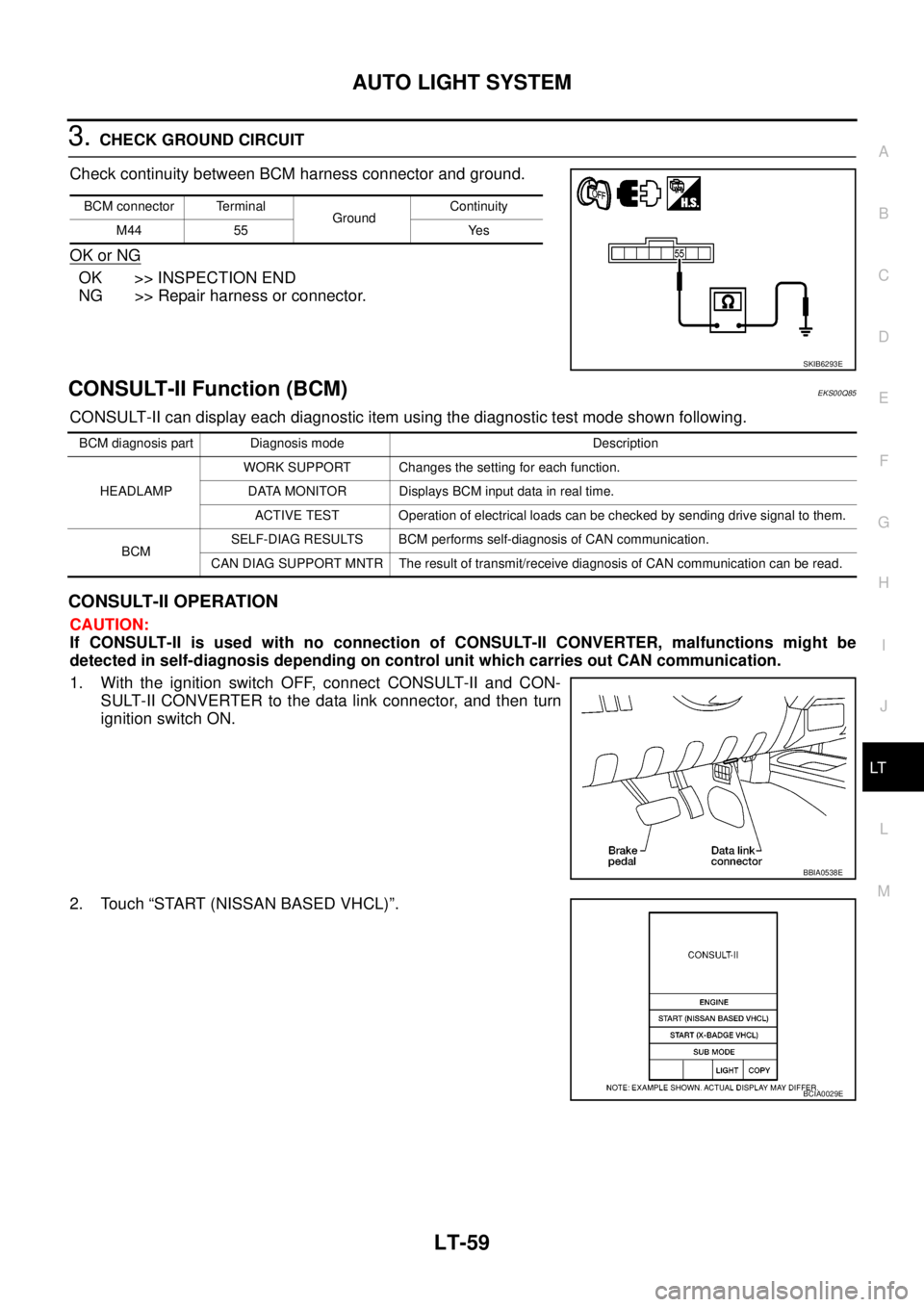
3.CHECK GROUND CIRCUIT
Check continuity between BCM harness connector and ground.
OK or NG
OK >> INSPECTION END
NG >> Repair harness or connector.
CONSULT-II Function (BCM)EKS00Q85
CONSULT-II can display each diagnostic item using the diagnostic test mode shown following.
CONSULT-II OPERATION
CAUTION:
If CONSULT-II is used with no connection of CONSULT-II CONVERTER, malfunctions might be
detected in self-diagnosis depending on control unit which carries out CAN communication.
1. With the ignition switch OFF, connect CONSULT-II and CON-
SULT-II CONVERTER to the data link connector, and then turn
ignition switch ON.
2. Touch “START (NISSAN BASED VHCL)”.
BCM connector Terminal
GroundContinuity
M44 55 Yes
SKIB6293E
BCM diagnosis part Diagnosis mode Description
HEADLAMPWORK SUPPORT Changes the setting for each function.
DATA MONITOR Displays BCM input data in real time.
ACTIVE TEST Operation of electrical loads can be checked by sending drive signal to them.
BCMSELF-DIAG RESULTS BCM performs self-diagnosis of CAN communication.
CAN DIAG SUPPORT MNTR The result of transmit/receive diagnosis of CAN communication can be read.
BBIA0538E
BCIA0029E
Page 2153 of 3171
LT-70
HEADLAMP AIMING CONTROL (MANUAL)
Removal and Installation
EKS00P3A
1. Remove lower instrument panel (driver side) (1). Refer toIP-10,
"Removal and Installation".
2. Press headlamp aiming switch (2) fixing pawl (A) and remove
unit from instrument lower panel (driver side) (1).
Switch Circuit InspectionEKS00P3B
Using a circuit tester, check resistance between headlamp aiming
switch connector terminals in each operation status of aiming switch.
SKIB6853E
PKIC0552E