Page 2462 of 3171
TROUBLE DIAGNOSIS
MTC-75
C
D
E
F
G
H
I
K
L
MA
B
MTC
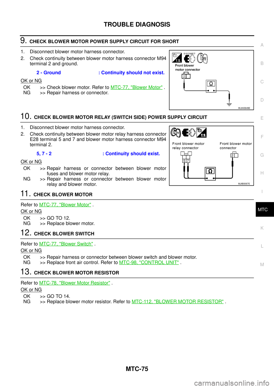
9.CHECK BLOWER MOTOR POWER SUPPLY CIRCUIT FOR SHORT
1. Disconnect blower motor harness connector.
2. Check continuity between blower motor harness connector M94
terminal 2 and ground.
OK or NG
OK >> Check blower motor. Refer toMTC-77, "Blower Motor".
NG >> Repair harness or connector.
10.CHECK BLOWER MOTOR RELAY (SWITCH SIDE) POWER SUPPLY CIRCUIT
1. Disconnect blower motor harness connector.
2. Check continuity between blower motor relay harness connector
E28 terminal 5 and 7 and blower motor harness connector M94
terminal 2.
OK or NG
OK >> Repair harness or connector between blower motor
fuses and blower motor relay.
NG >> Repair harness or connector between blower motor
relay and blower motor.
11 .CHECK BLOWER MOTOR
Refer toMTC-77, "
Blower Motor".
OK or NG
OK >> GO TO 12.
NG >> Replace blower motor.
12.CHECK BLOWER SWITCH
Refer toMTC-77, "
Blower Switch".
OK or NG
OK >> Repair harness or connector between blower switch and blower motor.
NG >> Replace front air control. Refer toMTC-98, "
CONTROL UNIT".
13.CHECK BLOWER MOTOR RESISTOR
Refer toMTC-78, "
Blower Motor Resistor".
OK or NG
OK >> GO TO 14.
NG >> Replace blower motor resistor. Refer toMTC-112, "
BLOWER MOTOR RESISTOR". 2 - Ground : Continuity should not exist.
WJIA0649E
5, 7 - 2 : Continuity should exist.
MJIB0067E
Page 2463 of 3171
MTC-76
TROUBLE DIAGNOSIS
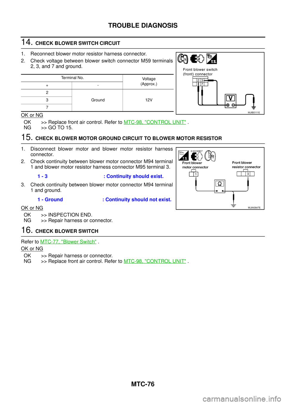
14.CHECK BLOWER SWITCH CIRCUIT
1. Reconnect blower motor resistor harness connector.
2. Check voltage between blower switch connector M59 terminals
2, 3, and 7 and ground.
OK or NG
OK >> Replace front air control. Refer toMTC-98, "CONTROL UNIT".
NG >> GO TO 15.
15.CHECK BLOWER MOTOR GROUND CIRCUIT TO BLOWER MOTOR RESISTOR
1. Disconnect blower motor and blower motor resistor harness
connector.
2. Check continuity between blower motor connector M94 terminal
1 and blower motor resistor harness connector M95 terminal 3.
3. Check continuity between blower motor connector M94 terminal
1 and ground.
OK or NG
OK >> INSPECTION END.
NG >> Repair harness or connector.
16.CHECK BLOWER SWITCH
Refer toMTC-77, "
Blower Switch".
OK or NG
OK >> Repair harness or connector.
NG >> Replace front air control. Refer toMTC-98, "
CONTROL UNIT".
Terminal No.
Voltage
(Approx.)
+-
2
Ground 12V 3
7
M J I B 0 111 E
1 - 3 : Continuity should exist.
1 - Ground : Continuity should not exist.
WJIA0647E
Page 2469 of 3171
MTC-82
TROUBLE DIAGNOSIS
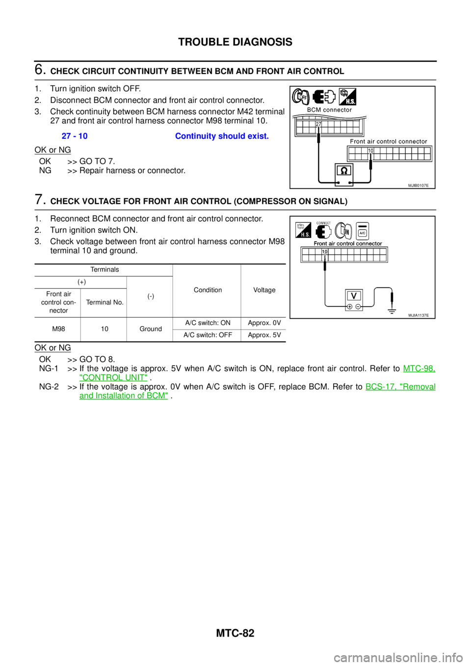
6.CHECK CIRCUIT CONTINUITY BETWEEN BCM AND FRONT AIR CONTROL
1. Turn ignition switch OFF.
2. Disconnect BCM connector and front air control connector.
3. Check continuity between BCM harness connector M42 terminal
27 and front air control harness connector M98 terminal 10.
OK or NG
OK >> GO TO 7.
NG >> Repair harness or connector.
7.CHECK VOLTAGE FOR FRONT AIR CONTROL (COMPRESSOR ON SIGNAL)
1. Reconnect BCM connector and front air control connector.
2. Turn ignition switch ON.
3. Check voltage between front air control harness connector M98
terminal 10 and ground.
OK or NG
OK >> GO TO 8.
NG-1 >> If the voltage is approx. 5V when A/C switch is ON, replace front air control. Refer toMTC-98,
"CONTROL UNIT".
NG-2 >> If the voltage is approx. 0V when A/C switch is OFF, replace BCM. Refer toBCS-17, "
Removal
and Installation of BCM". 27 - 10 Continuity should exist.
MJIB0107E
Terminals
Condition Voltage (+)
(-) Front air
control con-
nectorTerminal No.
M98 10 GroundA/C switch: ON Approx. 0V
A/C switch: OFF Approx. 5V
WJIA1137E
Page 2471 of 3171
MTC-84
TROUBLE DIAGNOSIS
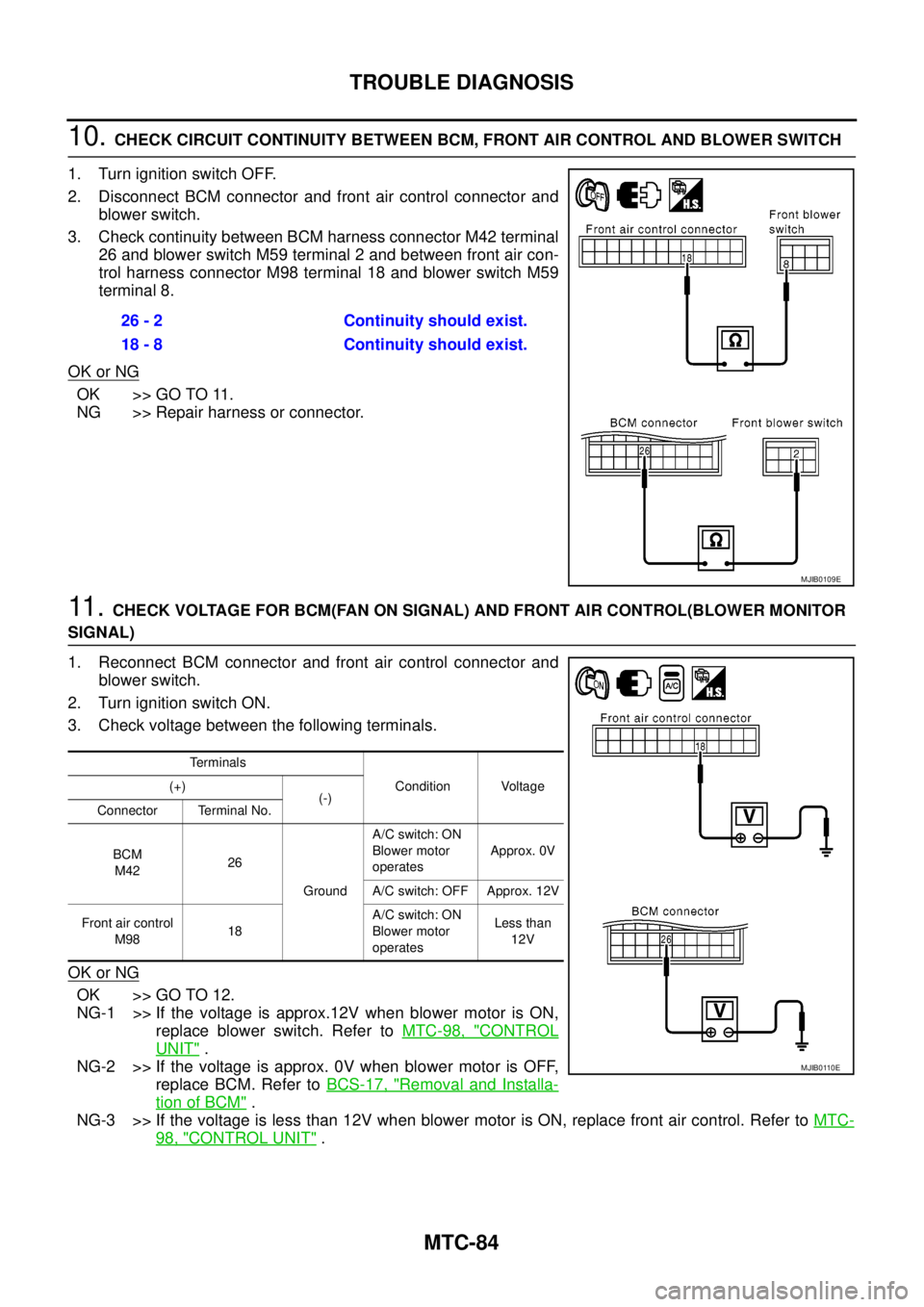
10.CHECK CIRCUIT CONTINUITY BETWEEN BCM, FRONT AIR CONTROL AND BLOWER SWITCH
1. Turn ignition switch OFF.
2. Disconnect BCM connector and front air control connector and
blower switch.
3. Check continuity between BCM harness connector M42 terminal
26 and blower switch M59 terminal 2 and between front air con-
trol harness connector M98 terminal 18 and blower switch M59
terminal 8.
OK or NG
OK >> GO TO 11.
NG >> Repair harness or connector.
11 .CHECK VOLTAGE FOR BCM(FAN ON SIGNAL) AND FRONT AIR CONTROL(BLOWER MONITOR
SIGNAL)
1. Reconnect BCM connector and front air control connector and
blower switch.
2. Turn ignition switch ON.
3. Check voltage between the following terminals.
OK or NG
OK >> GO TO 12.
NG-1 >> If the voltage is approx.12V when blower motor is ON,
replace blower switch. Refer toMTC-98, "
CONTROL
UNIT".
NG-2 >> If the voltage is approx. 0V when blower motor is OFF,
replace BCM. Refer toBCS-17, "
Removal and Installa-
tion of BCM".
NG-3 >> If the voltage is less than 12V when blower motor is ON, replace front air control. Refer toMTC-
98, "CONTROL UNIT". 26 - 2 Continuity should exist.
18 - 8 Continuity should exist.
MJIB0109E
Terminals
Condition Voltage (+)
(-)
Connector Terminal No.
BCM
M4226
GroundA/C switch: ON
Blower motor
operatesApprox. 0V
A/C switch: OFF Approx. 12V
Front air control
M9818A/C switch: ON
Blower motor
operatesLess than
12V
MJIB0110E
Page 2482 of 3171
TROUBLE DIAGNOSIS
MTC-95
C
D
E
F
G
H
I
K
L
MA
B
MTC
Self-diagnosisEJS005GP
SYMPTOM: Self-diagnosis cannot be performed (Vehicles equipped with NAVI only).
INSPECTION FLOW
Intake Sensor CircuitEJS005GR
COMPONENT DESCRIPTION
Intake Sensor
The intake sensor is located on the heater & cooling unit. It converts
temperature of air after it passes through the evaporator into a resis-
tance value which is then input to the front air control.
NOTE:
This illustration is for LHD models.
The layout for RHD models is symmetrically opposite.
*1MTC-122, "REMOVAL".*2MTC-122, "INSTALLATION".*3MTC-24, "Maintenance of Lubricant
Quantity in Compressor".
*4MTC-53, "
Operational Check".*5EM-12, "DRIVE BELTS".
*1MTC-55, "
Power Supply and Ground
Circuit for Front Air Control".2.MTC-63, "
Air Mix Door Motor Cir-
cuit".3.MTC-53, "
Operational Check".
MJIB0246E
MJIB0198E
Page 2485 of 3171
MTC-98
CONTROL UNIT
CONTROL UNIT
PFP:27500
Removal and InstallationEJS005GS
REMOVAL
1. Remove the five control knobs from the front air control unit.
2. Remove the cluster lid C. Refer toIP-11, "
CLUSTER LID C".
3. Remove the four screws securing the front air control unit to the
cluster lid C.
4. Remove the front air control unit.
INSTALLATION
Installation is in the reverse order of removal.
LJIA0130E
Page 2488 of 3171
AIR CONDITIONER FILTER
MTC-101
C
D
E
F
G
H
I
K
L
MA
B
MTC
AIR CONDITIONER FILTERPFP:27277
Removal and InstallationEJS005GW
FUNCTION
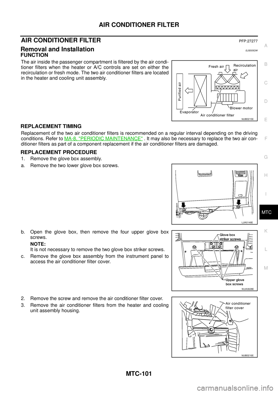
The air inside the passenger compartment is filtered by the air condi-
tioner filters when the heater or A/C controls are set on either the
recirculation or fresh mode. The two air conditioner filters are located
in the heater and cooling unit assembly.
REPLACEMENT TIMING
Replacement of the two air conditioner filters is recommended on a regular interval depending on the driving
conditions. Refer toMA-8, "
PERIODIC MAINTENANCE". It may also be necessary to replace the two air con-
ditioner filters as part of a component replacement if the air conditioner filters are damaged.
REPLACEMENT PROCEDURE
1. Remove the glove box assembly.
a. Remove the two lower glove box screws.
b. Open the glove box, then remove the four upper glove box
screws.
NOTE:
It is not necessary to remove the two glove box striker screws.
c. Remove the glove box assembly from the instrument panel to
access the air conditioner filter cover.
2. Remove the screw and remove the air conditioner filter cover.
3. Remove the air conditioner filters from the heater and cooling
unit assembly housing.
MJIB0215E
LJIA0146E
WJIA0628E
MJIB0216E
Page 2520 of 3171
REFRIGERANT LINES
MTC-133
C
D
E
F
G
H
I
K
L
MA
B
MTC
CHECKING PROCEDURE
To prevent inaccurate or false readings, make sure there is no refrigerant vapor, shop chemicals, or cigarette
smoke in the vicinity of the vehicle. Perform the leak test in calm area (low air/wind movement) so that the
leaking refrigerant is not dispersed.
1. Turn engine OFF.
2. Connect a suitable A/C manifold gauge set (SST) to the A/C service valves.
3. Check if the A/C refrigerant pressure is at least 345 kPa (3.45 bar, 3.52 kg/cm
2, 50 psi) above 16°C. If
less than specification, recover/evacuate and recharge the system with the specified amount of refriger-
ant.
NOTE:
At temperatures below 16°C, leaks may not be detected since the system may not reach 345 kPa (3.45
bar, 3.52 kg/cm
2,50psi).
4. Perform the leak test from the high-pressure side (compressor discharge a to evaporator inlet g) to the
low-pressure side (evaporator drain hose h to shaft seal l). Refer toMTC-120, "
Components". Perform a
leak check for the following areas carefully. Clean the component to be checked and move the leak
detected probe completely around the connection/component.
Compressor
Check the fitting of high- and low-pressure flexible hoses, relief valve and shaft seal.
Liquid tank
Check the refrigerant pressure sensor.
Service valves
Check all around the service valves. Ensure service valve caps are secured on the service valves (to pre-
vent leaks).
NOTE:
After removing A/C manifold gauge set from service valves, wipe any residue from valves to prevent any
false readings by leak detector.
Cooling unit (Evaporator)
With engine OFF, turn blower fan on “High” for at least 15 seconds to dissipate any refrigerant trace in the
cooling unit. Wait a minimum of 10 minutes accumulation time (refer to the manufacturer’s recommended
procedure for actual wait time) before inserting the leak detector probe into the drain hose.
Keep the probe inserted for at least 10 seconds. Use caution not to contaminate the probe tip with water
or dirt that may be in the drain hose.
5. If a leak detector detects a leak, verify at least once by blowing compressed air into area of suspected
leak, then repeat check as outlined above.
6. Do not stop when one leak is found. Continue to check for additional leaks at all system components.
If no leaks are found, perform steps 7 - 10.
7. Start engine.
8. Set the heater A/C control as follows;
a. A/C switch: ON
b. MODE control dial: VENT (Ventilation)
c. Intake door position: Recirculation
d. Max. cold temperature
e. Fan speed: High
9. Run engine at 1,500 rpm for at least 2 minutes.
10. Turn engine off and perform leak check again following steps 4 through 6 above.
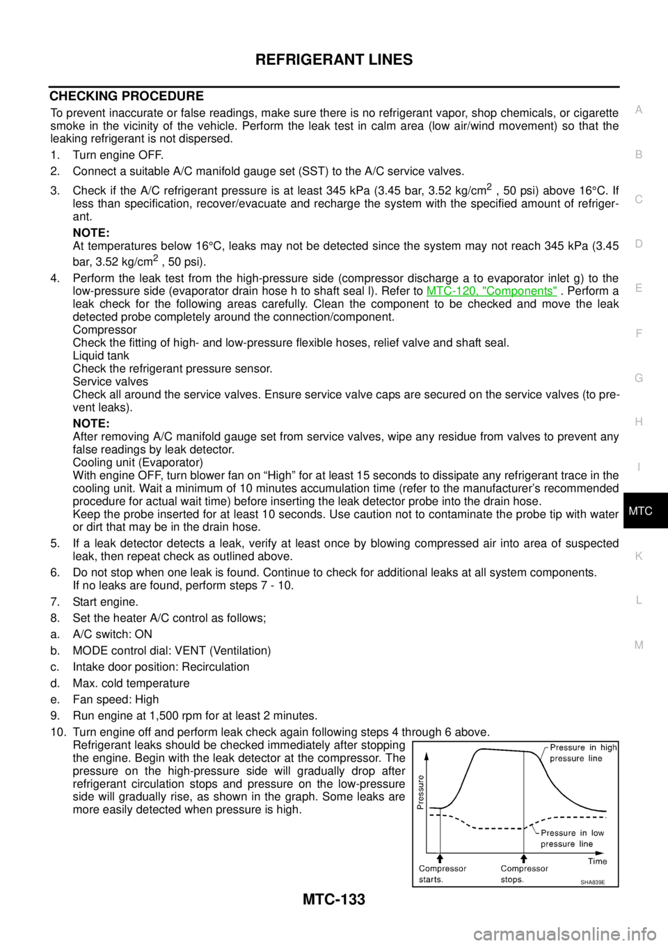
Refrigerant leaks should be checked immediately after stopping
the engine. Begin with the leak detector at the compressor. The
pressure on the high-pressure side will gradually drop after
refrigerant circulation stops and pressure on the low-pressure
side will gradually rise, as shown in the graph. Some leaks are
more easily detected when pressure is high.
SHA839E