2005 NISSAN NAVARA control unit
[x] Cancel search: control unitPage 2543 of 3171

PG-14
IPDM E/R (INTELLIGENT POWER DISTRIBUTION MODULE ENGINE ROOM)
IPDM E/R (INTELLIGENT POWER DISTRIBUTION MODULE ENGINE ROOM)
PFP:284B7
System DescriptionEKS00PA8
lIPDM E/R (Intelligent Power Distribution Module Engine Room) integrates the relay box and fuse block
which were originally placed in engine compartment. It controls integrated relays via IPDM E/R control cir-
cuits.
lIPDM E/R-integrated control circuits perform ON-OFF operation of relays, CAN communication control,
etc.
lIt controls operation of each electrical component via ECM, BCM and CAN communication lines.
CAUTION:
None of the IPDM E/R integrated relays can be removed.
SYSTEMS CONTROLLED BY IPDM E/R
IPDM E/R receives a request signal from each Control unit with CAN communication. It controls each system.
CAN COMMUNICATION LINE CONTROL
With CAN communication, by connecting each control unit using two communication lines (CAN L-line, CAN
H-line), it is possible to transmit a maximum amount of information with minimum wiring. Each control unit can
transmit and receive data, and reads necessary information only.
1. Fail-safe control
lWhen CAN communication with other control units is impossible, IPDM E/R performs fail-safe control.
After CAN communication returns to normal operation, it also returns to normal control.
lOperation of control parts by IPDM E/R during fail-safe mode is as follows:
Control system Transmit control unit Control part
Lamp control BCM
lHead lamps (HI, LO)
lTail lamps, parking and license plate lamps
lFront fog lamps
Wiper control BCM Front wipers
Rear window defogger control BCM Rear window defogger
A/C compressor control ECM A/C compressor
Starter control TCM Starter motor
Cooling fan control ECM Cooling fan
Controlled system Fail-safe mode
Headlamps
lWith the ignition switch ON, the headlamp low is ON.
lWith the ignition switch OFF, the headlamp low is OFF.
Tail, parking and license plate lamps
lWith the ignition switch ON, the tail lamp is ON.
lWith the ignition switch OFF, the tail lamp is OFF.
Cooling fan
lWith the ignition switch ON, the cooling fan HI operates.
lWith the ignition switch OFF, the cooling fan stops.
Front wipersUntil the ignition switch is turned off, the front wiper LO and HI remains in the same status it
was in just before fail-safe control was initiated.
Rear window defogger Rear window defogger OFF
A/C compressor A/C compressor OFF
Front fog lamps Front fog lamp OFF
Page 2544 of 3171

IPDM E/R (INTELLIGENT POWER DISTRIBUTION MODULE ENGINE ROOM)
PG-15
C
D
E
F
G
H
I
J
L
MA
B
PG
IPDM E/R STATUS CONTROL
In order to save power, IPDM E/R switches status by itself based on each operating condition.
1. CAN communication status
lCAN communication is normally performed with other control units.
lIndividual unit control by IPDM E/R is normally performed.
lA status is changed into sleep transient status when receiving a sleep request signal from BCM while
all the systems controlled by IPDM E/R under suspension.
2. Sleep transient status
lProcess to stop CAN communication is activated.
lAll systems controlled by IPDM E/R are stopped. When 3 second has elapsed after CAN communica-
tion with other control units is stopped, status switches to sleep status.
3. Sleep status
lIPDM E/R operates in low power mode.
lCAN communication is stopped.
lWhen a change in CAN communication signal is detected, status switches to CAN communication sta-
tus.
lWhen a change in ignition switch signal is detected, status switches to CAN communication status.
CAN Communication System DescriptionEKS00PA9
Refer toLAN-23, "CAN COMMUNICATION".
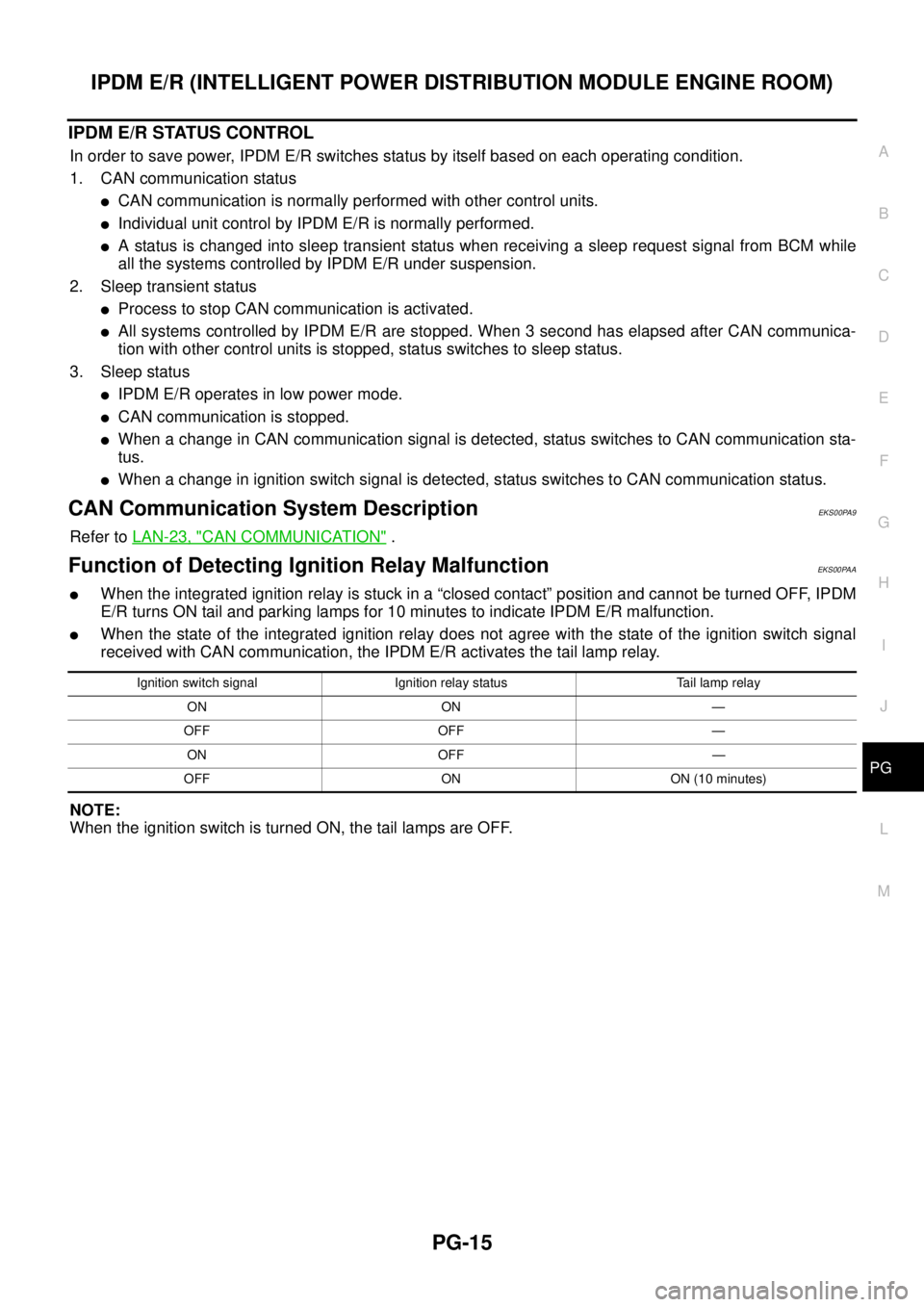
Function of Detecting Ignition Relay MalfunctionEKS00PAA
lWhen the integrated ignition relay is stuck in a “closed contact” position and cannot be turned OFF, IPDM
E/R turns ON tail and parking lamps for 10 minutes to indicate IPDM E/R malfunction.
lWhen the state of the integrated ignition relay does not agree with the state of the ignition switch signal
received with CAN communication, the IPDM E/R activates the tail lamp relay.
NOTE:
When the ignition switch is turned ON, the tail lamps are OFF.
Ignition switch signal Ignition relay status Tail lamp relay
ON ON —
OFF OFF —
ON OFF —
OFF ON ON (10 minutes)
Page 2545 of 3171

PG-16
IPDM E/R (INTELLIGENT POWER DISTRIBUTION MODULE ENGINE ROOM)
CONSULT-II Function (IPDM E/R)
EKS00PAB
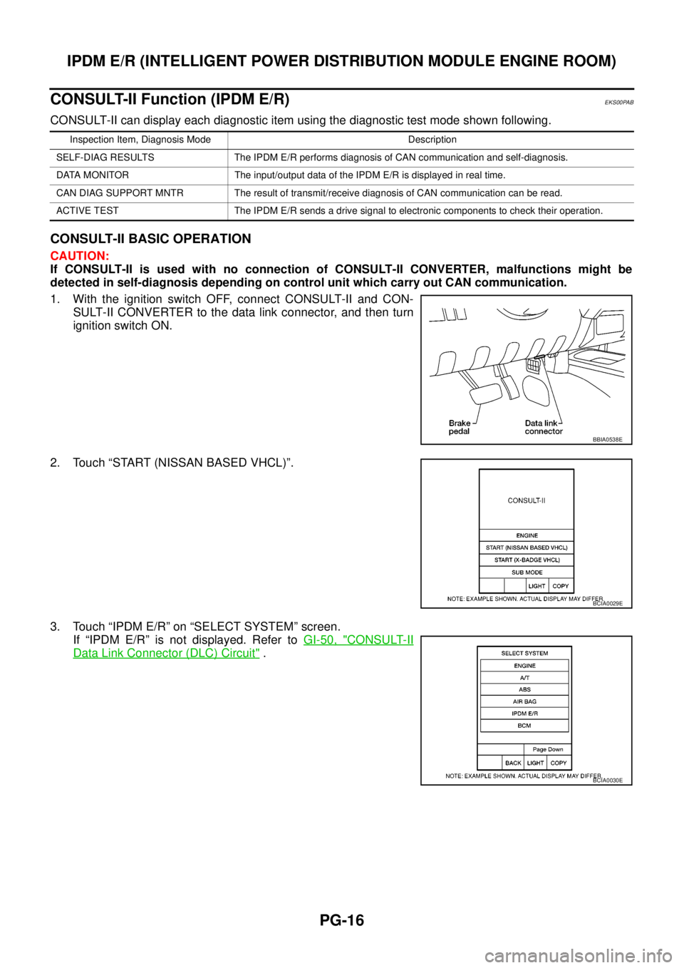
CONSULT-II can display each diagnostic item using the diagnostic test mode shown following.
CONSULT-II BASIC OPERATION
CAUTION:
If CONSULT-II is used with no connection of CONSULT-II CONVERTER, malfunctions might be
detected in self-diagnosis depending on control unit which carry out CAN communication.
1. With the ignition switch OFF, connect CONSULT-II and CON-
SULT-II CONVERTER to the data link connector, and then turn
ignition switch ON.
2. Touch “START (NISSAN BASED VHCL)”.
3. Touch “IPDM E/R” on “SELECT SYSTEM” screen.
If “IPDM E/R” is not displayed. Refer toGI-50, "
CONSULT-II
Data Link Connector (DLC) Circuit".
Inspection Item, Diagnosis Mode Description
SELF-DIAG RESULTS The IPDM E/R performs diagnosis of CAN communication and self-diagnosis.
DATA MONITOR The input/output data of the IPDM E/R is displayed in real time.
CAN DIAG SUPPORT MNTR The result of transmit/receive diagnosis of CAN communication can be read.
ACTIVE TEST The IPDM E/R sends a drive signal to electronic components to check their operation.
BBIA0538E
BCIA0029E
BCIA0030E
Page 2546 of 3171

IPDM E/R (INTELLIGENT POWER DISTRIBUTION MODULE ENGINE ROOM)
PG-17
C
D
E
F
G
H
I
J
L
MA
B
PG
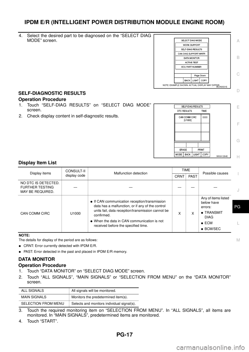
4. Select the desired part to be diagnosed on the “SELECT DIAG
MODE” screen.
SELF-DIAGNOSTIC RESULTS
Operation Procedure
1. Touch “SELF-DIAG RESULTS” on “SELECT DIAG MODE”
screen.
2. Check display content in self-diagnostic results.
Display Item List
NOTE:
The details for display of the period are as follows:
lCRNT: Error currently detected with IPDM E/R.
lPAST: Error detected in the past and placed in IPDM E/R memory.
DATA MONITOR
Operation Procedure
1. Touch “DATA MONITOR” on “SELECT DIAG MODE” screen.
2. Touch “ALL SIGNALS”, “MAIN SIGNALS” or “SELECTION FROM MENU” on the “DATA MONITOR”
screen.
3. Touch the required monitoring item on “SELECTION FROM MENU”. In “ALL SIGNALS”, all items are
monitored. In “MAIN SIGNALS”, predetermined items are monitored.
4. Touch “START”.
BCIA0031E
WKIA1264E
Display itemsCONSULT-II
display codeMalfunction detectionTIME
Possible causes
CRNT PAST
NO DTC IS DETECTED.
FURTHER TESTING
MAYBEREQUIRED.—————
CAN COMM CIRC U1000
lIf CAN communication reception/transmission
data has a malfunction, or if any of the control
units fail, data reception/transmission cannot be
confirmed.
lWhen the data in CAN communication is not
received before the specified time.XXAny of items listed
below have
errors:
lTRANSMIT
DIAG
lECM
lBCM/SEC
ALL SIGNALS All signals will be monitored.
MAIN SIGNALS Monitors the predetermined item(s).
SELECTION FROM MENU Selects and monitors individual signal(s).
Page 2547 of 3171

PG-18
IPDM E/R (INTELLIGENT POWER DISTRIBUTION MODULE ENGINE ROOM)
5. Touch “RECORD” while monitoring to record the status of the item being monitored. To stop recording,
touch “STOP”.
All Signals, Main Signals, Selection From Menu
NOTE:
Perform monitoring of IPDM E/R data with the ignition switch ON. When the ignition switch is in ACC position,
display may not be correct.
CAN DIAG SUPPORT MNTR
Refer toLAN-15, "CAN Diagnostic Support Monitor".
ACTIVE TEST
Operation Procedure
1. Touch “ACTIVE TEST” on “SELECT DIAG-MODE” screen.
2. Touch item to be tested, and check operation.
3. Touch “START”.
4. Touch “STOP” while testing to stop the operation.
Item nameCONSULT-II
screen displayDisplay or unitMonitor item selection
Description
ALL
SIGNALSMAIN
SIGNALSSELECTION
FROM MENU
Motor fan requestMOTOR FAN
REQ1/2/3/4 X X X Signal status input from ECM
A/C compressor
requestAC COMP REQ ON/OFF X X X Signal status input from ECM
Tail & clear
requestTAIL & CLR REQ ON/OFF X X X Signal status input from BCM
Headlamp LO
requestHL LO REQ ON/OFF X X X Signal status input from BCM
Headlamp HI
requestHL HI REQ ON/OFF X X X Signal status input from BCM
Front fog lamp
requestFR FOG REQ ON/OFF X X X Signal status input from BCM
Headlamp washer
requestHL WASHER
REQON/OFF X X Signal from input from BCM
Front wiper
requestFR WIP REQSTOP/1LOW/
LOW/HIX X X Signal status input from BCM
Wiper auto stopWIP AUTO
STOPACT P/STOP P X X X Output status of IPDM E/R
Wiper protection WIP PROT OFF/BLOCK X X X Control status of IPDM E/R
Starter request ST RLY REQ ON/OFF X X
Status of input signal
NOTE
Ignition relay
statusIGN RLY ON/OFF X X XIgnition relay status monitored
with IPDM E/R
Rear defogger
requestRR DEF REQ ON/OFF X X X Signal status input from BCM
Oil pressure
switchOIL P SW OPEN/CLOSE X XSignal status input from IPDM
E/R
Hood switch HOOD SW OFF XSignal status input from IPDM
E/R (function is not enabled)
Theft warning
horn requestTHFT HRN REQ ON/OFF X X Signal status input from BCM
Horn chirp HORN CHIRP ON/OFF X X Output status of IPDM E/R
Page 2554 of 3171

IPDM E/R (INTELLIGENT POWER DISTRIBUTION MODULE ENGINE ROOM)
PG-25
C
D
E
F
G
H
I
J
L
MA
B
PG
Inspection with CONSULT-II (Self-Diagnosis)EKS00PAG
CAUTION:
If a CONSULT-II is used with no connection of CONSULT-II CONVERTER, malfunctions might be
detected in self-diagnosis depending on which control unit(s) carry out CAN communication.
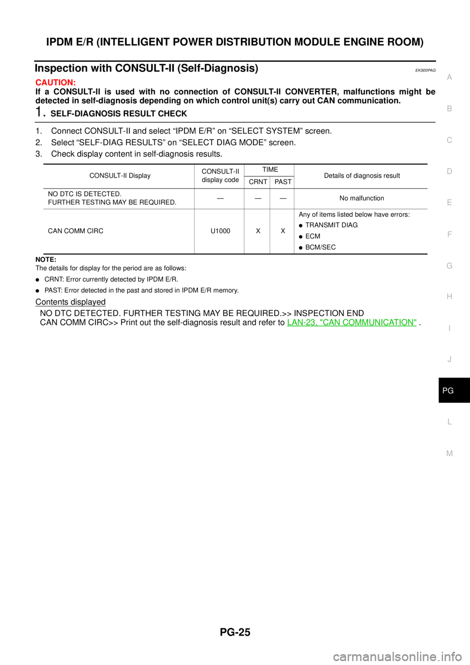
1.SELF-DIAGNOSIS RESULT CHECK
1. Connect CONSULT-II and select “IPDM E/R” on “SELECT SYSTEM” screen.
2. Select “SELF-DIAG RESULTS” on “SELECT DIAG MODE” screen.
3. Check display content in self-diagnosis results.
NOTE:
The details for display for the period are as follows:
lCRNT: Error currently detected by IPDM E/R.
lPAST: Error detected in the past and stored in IPDM E/R memory.
Contents displayed
NO DTC DETECTED. FURTHER TESTING MAY BE REQUIRED.>> INSPECTION END
CAN COMM CIRC>> Print out the self-diagnosis result and refer toLAN-23, "
CAN COMMUNICATION".
CONSULT-II DisplayCONSULT-II
display codeTIME
Details of diagnosis result
CRNT PAST
NO DTC IS DETECTED.
FURTHER TESTING MAY BE REQUIRED.— — — No malfunction
CAN COMM CIRC U1000 X XAny of items listed below have errors:
lTRANSMIT DIAG
lECM
lBCM/SEC
Page 2683 of 3171

RF-6
SQUEAK AND RATTLE TROUBLE DIAGNOSES
FELT CLOTHTAPE
Used to insulate where movement does not occur. Ideal for instrument panel applications.
68370-4B000: 15´25 mm (0.59´0.98 in) pad/68239-13E00: 5 mm (0.20 in) wide tape roll
The following materials, not available through NISSAN Parts Department, can also be used to repair squeaks
and rattles.
UHMW(TEFLON) TAPE
Insulates where slight movement is present. Ideal for instrument panel applications.
SILICONE GREASE
Used in place of UHMW tape that will be visible or not fit.
Note: Will only last a few months.
SILICONE SPRAY
Use when grease cannot be applied.
DUCT TAPE
Use to eliminate movement.
CONFIRM THE REPAIR
Confirm that the cause of a noise is repaired by test driving the vehicle. Operate the vehicle under the same
conditions as when the noise originally occurred. Refer to the notes on the Diagnostic Worksheet.
Generic Squeak and Rattle TroubleshootingEIS00CDZ
Refer to Table of Contents for specific component removal and installation information.
INSTRUMENT PANEL
Most incidents are caused by contact and movement between:
1. Cluster lid A and instrument panel
2. Acrylic lens and combination meter housing
3. Instrument panel to front pillar garnish
4. Instrument panel to windshield
5. Instrument panel mounting pins
6. Wiring harnesses behind the combination meter
7. A/C defroster duct and duct joint
These incidents can usually be located by tapping or moving the components to duplicate the noise or by
pressing on the components while driving to stop the noise. Most of these incidents can be repaired by apply-
ing felt cloth tape or silicon spray (in hard to reach areas). Urethane pads can be used to insulate wiring har-
ness.
CAUTION:
Do not use silicone spray to isolate a squeak or rattle. If you saturate the area with silicone, you will
not be able to recheck the repair.
CENTER CONSOLE
Components to pay attention to include:
1. Shifter assembly cover to finisher
2. A/C control unit and cluster lid C
3. Wiring harnesses behind audio and A/C control unit
The instrument panel repair and isolation procedures also apply to the center console.
DOORS
Pay attention to the:
1. Finisher and inner panel making a slapping noise
2. Inside handle escutcheon to door finisher
3. Wiring harnesses tapping
4. Door striker out of alignment causing a popping noise on starts and stops
Tapping or moving the components or pressing on them while driving to duplicate the conditions can isolate
many of these incidents. You can usually insulate the areas with felt cloth tape or insulator foam blocks to
repair the noise.
Page 2690 of 3171

SUNROOF
RF-13
C
D
E
F
G
H
J
K
L
MA
B
RF
CAN Communication System DescriptionEIS00D4X
CAN (Controller Area Network) is a serial communication line for real time application. It is an on-vehicle mul-
tiplex communication line with high data communication speed and excellent error detection ability. Many elec-
tronic control units are equipped onto a vehicle, and each control unit shares information and links with other
control units during operation (not independent). In CAN communication, control units are connected with 2
communication lines (CAN H line, CAN L line) allowing a high rate of information transmission with less wiring.
Each control unit transmits/receives data but selectively reads required data only.
CAN Communication UnitEIS00D4Y
Refer toLAN-30, "CAN Communication Unit".