2005 NISSAN NAVARA key fob
[x] Cancel search: key fobPage 724 of 3171

BL-140
THEFT WARNING SYSTEM
System Description
EIS00DBX
DESCRIPTION
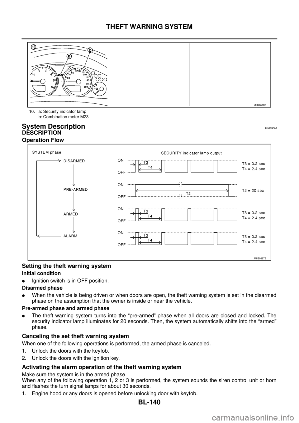
Operation Flow
Setting the theft warning system
Initial condition
lIgnition switch is in OFF position.
Disarmed phase
lWhen the vehicle is being driven or when doors are open, the theft warning system is set in the disarmed
phase on the assumption that the owner is inside or near the vehicle.
Pre-armed phase and armed phase
lThe theft warning system turns into the “pre-armed” phase when all doors are closed and locked. The
security indicator lamp illuminates for 20 seconds. Then, the system automatically shifts into the “armed”
phase.
Canceling the set theft warning system
When one of the following operations is performed, the armed phase is canceled.
1. Unlock the doors with the keyfob.
2. Unlock the doors with the ignition key.
Activating the alarm operation of the theft warning system
Make sure the system is in the armed phase.
When any of the following operation 1, 2 or 3 is performed, the system sounds the siren control unit or horn
and flashes the turn signal lamps for about 30 seconds.
1. Engine hood or any doors is opened before unlocking door with keyfob.
10. a: Security indicator lamp
b: Combination meter M23
MIIB1032E
MIIB0867E
Page 725 of 3171

THEFT WARNING SYSTEM
BL-141
C
D
E
F
G
H
J
K
L
MA
B
BL
2. A door is unlocked without using the keyfob.
3. Disconnect and connecting the battery connector before canceling armed phase.
POWER SUPPLY AND GROUND CIRCUIT
Power is supplied at all times
lthrough 10A fuse [No.19, located in the fuse block (J/B)]
lto combination meter (security indicator lamp) terminal 3
lthrough 50A fusible link (letterG, located in the fuse and fusible link box)
lto BCM terminal 57
lthrough 10A fuse [No. 21, located in the fuse block (J/B)]
lto BCM terminal 41
lthrough 15A fuse (No. 30, located in the fuse and fusible link box)
lto horn relay terminal 2
lthrough 20A fuse (No. 52, located in the IPDM E/R)
lthrough 20A fuse (No. 53, located in the IPDM E/R),
lto IPDM E/R internal CPU.
With the ignition switch in the ACC or ON position, power is supplied
lthrough 10A fuse [No. 4, located in the fuse block (J/B)]
lto BCM terminal 4.
Ground is supplied
lto BCM terminal 55
lthrough body grounds M21, M80 and M83
lto IPDM E/R terminals 38 and 59
lthrough body ground E21, E41 and E61.
INITIAL CONDITION TO ACTIVATE THE SYSTEM
The operation of the theft warning system is controlled by the engine hood and doors.
To activate the theft warning system, BCM must receive signals indicating the doors are closed and locked.
When a door is open, BCM terminal 12, 14, 15 or 16 receives a ground signal from each door switch.
When the engine hood is open, IPDM E/R terminal 41 receives a ground signal
THEFT WARNING SYSTEM ALARM OPERATION
The vehicle security system is triggered by
lopening a door
lopening the hood
ldetecting battery disconnect/connection.
The vehicle security system will be triggered once the system is in armed phase,
when BCM receives a ground signal at terminals 12, 14, 15, 16 (door switch) or IPDM E/R receives a ground
signal at terminal 41 (hood switch).
When the vehicle security system is triggered, siren control unit or horn is activate.
The alarm automatically turns off after 30 seconds, but will reactivate if the vehicle is tampered with again.
THEFT WARNING SYSTEM DEACTIVATION
To deactivate the theft warning system, a door must be unlocked with keyfob.
When the BCM receives either one of these signals or unlock signal from keyfob the theft warning system is
deactivated. (Disarmed phase)
CAN Communication System DescriptionEIS00DBY
Refer toLAN-23, "CAN COMMUNICATION".
Page 740 of 3171

BL-156
THEFT WARNING SYSTEM
TerminalsandReferenceValueforIPDME/R
EIS00DC3
*: When horn reminder is ON.
CONSULT-II Function (BCM)EIS00DC4
CONSULT-II can display each diagnostic item using the diagnostic test modes shown following.
CONSULT-II INSPECTION PROCEDURE
CAUTION:
If CONSULT-II is used with no connection of CONSULT-II CONVERTER, malfunctions might be
detected in self-diagnosis depending on control unit which carry out CAN communication.
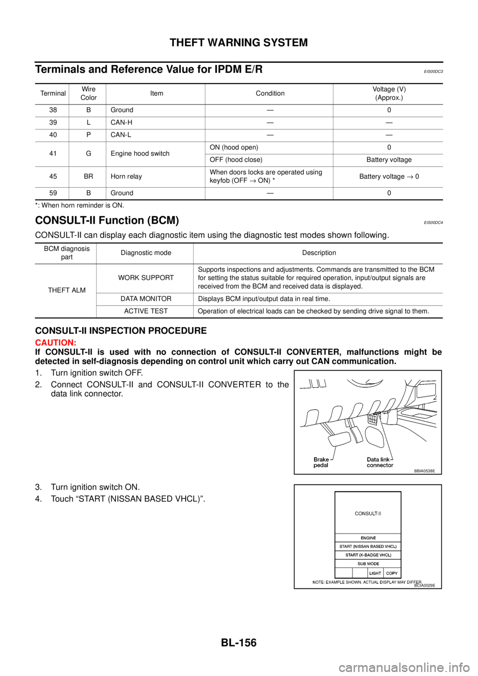
1. Turn ignition switch OFF.
2. Connect CONSULT-II and CONSULT-II CONVERTER to the
data link connector.
3. Turn ignition switch ON.
4. Touch “START (NISSAN BASED VHCL)”.
TerminalWire
ColorItem ConditionVoltage (V)
(Approx.)
38 B Ground — 0
39 L CAN-H — —
40 P CAN-L — —
41 G Engine hood switchON (hood open) 0
OFF (hood close) Battery voltage
45 BR Horn relayWhen doors locks are operated using
keyfob (OFF®ON) *Battery voltage®0
59 B Ground — 0
BCM diagnosis
partDiagnostic mode Description
THEFT ALMWORK SUPPORTSupports inspections and adjustments. Commands are transmitted to the BCM
for setting the status suitable for required operation, input/output signals are
received from the BCM and received data is displayed.
DATA MONITOR Displays BCM input/output data in real time.
ACTIVE TEST Operation of electrical loads can be checked by sending drive signal to them.
BBIA0538E
BCIA0029E
Page 741 of 3171

THEFT WARNING SYSTEM
BL-157
C
D
E
F
G
H
J
K
L
MA
B
BL
5. Touch “BCM”.
If “BCM” is not indicated, refer toGI-50, "
CONSULT-II Data Link
Connector (DLC) Circuit".
6. Touch “THEFT ALM” on the “SELECT TEST ITEM” screen.
7. Select diagnosis mode.
“DATA MONITOR”, “ACTIVE TEST” and “WORK SUPPORT”
are available.
CONSULT-II APPLICATION ITEM
Data Monitor
BCIA0030E
LIIA0034E
BCIA0031E
Monitored Item Description
IGN ON SW Indicates [ON/OFF] condition of ignition switch.
ACC ON SW Indicates [ON/OFF] condition of ignition switch in ACC position.
KEY ON SW Indicates [ON/OFF] condition of key switch.
KEYLESS LOCK Indicates [ON/OFF] condition of lock signal from key fob.
KEYLESS UNLOCK Indicates [ON/OFF] condition of unlock signal from key fob.
KEYLESS TRUNK This is displayed even when it is not equipped.
TRUNK OPNR SW This is displayed even when it is not equipped.
TRUNK CYL SW This is displayed even when it is not equipped.
TRUNK OPN MNTR This is displayed even when it is not equipped.
HOOD SW Indicates [ON/OFF] condition of hood switch.
DOOR SW-DR Indicates [ON/OFF] condition of front door switch driver side.
DOOR SW-AS Indicates [ON/OFF] condition of front door switch passenger side.
DOOR SW-RR Indicates [ON/OFF] condition of rear door switch RH.
DOOR SW-RL Indicates [ON/OFF] condition of rear door switch LH.
BACK DOOR SW This is displayed even when it is not equipped.
Page 745 of 3171

THEFT WARNING SYSTEM
BL-161
C
D
E
F
G
H
J
K
L
MA
B
BL
Symptom ChartEIS00DC7
*1: Make sure the system is in the armed phase.PROCEDURE
Diagnostic procedure Reference page
SYMPTOM
1Vehicle secu-
rity system
cannot be set
by ····Door switchDiagnostic Procedure 1 (Door, hood and trunk room lamp switch
check)BL-162
Key fob Check remote keyless entry system function.BL-89
BCM If the above systems are “OK”, replace BCM.BCS-17
Security indicator does not turn “ON”.Diagnostic Procedure 2 (Security indicator lamp check)BL-168If the above systems are “OK”, replace BCM.BCS-17
2*1 Vehicle
security sys-
tem does not
alarm when
····Any door is opened.Diagnostic Procedure 1 (Door, hood and trunk room lamp switch
check)BL-162
If the above systems are “OK”, replace BCM.BCS-17
3Vehicle secu-
rity alarm
does not acti-
vate.Horn alarmDiagnostic Procedure 3 (Vehicle security horn alarm check)BL-169If the above systems are “OK”, replace BCM.BCS-17
Turn signal lamp
alarmDiagnostic Procedure 4 (Turn signal lamp alarm check)BL-169
If the above systems are “OK”, replace BCM.BCS-17
4Vehicle secu-
rity system
cannot be
canceled by
····Key fobCheck remote keyless entry system function.BL-89If the above systems are “OK”, replace BCM.BCS-17
Page 2228 of 3171

INTERIOR ROOM LAMP
LT-145
C
D
E
F
G
H
I
J
L
MA
B
LT
INTERIOR ROOM LAMPPFP:26410
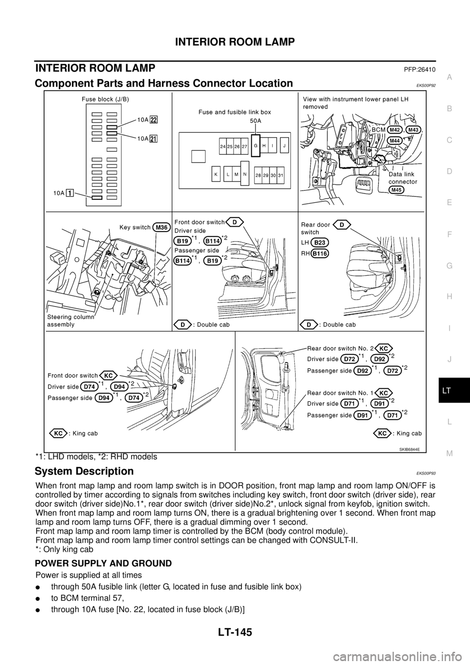
Component Parts and Harness Connector LocationEKS00P92
*1: LHD models, *2: RHD models
System DescriptionEKS00P93
When front map lamp and room lamp switch is in DOOR position, front map lamp and room lamp ON/OFF is
controlled by timer according to signals from switches including key switch, front door switch (driver side), rear
door switch (driver side)No.1*, rear door switch (driver side)No.2*, unlock signal from keyfob, ignition switch.
When front map lamp and room lamp turns ON, there is a gradual brightening over 1 second. When front map
lamp and room lamp turns OFF, there is a gradual dimming over 1 second.
Front map lamp and room lamp timer is controlled by the BCM (body control module).
Front map lamp and room lamp timer control settings can be changed with CONSULT-II.
*: Only king cab
POWER SUPPLY AND GROUND
Power is supplied at all times
lthrough 50A fusible link (letter G, located in fuse and fusible link box)
lto BCM terminal 57,
lthrough 10A fuse [No. 22, located in fuse block (J/B)]
SKIB6844E
Page 2230 of 3171

INTERIOR ROOM LAMP
LT-147
C
D
E
F
G
H
I
J
L
MA
B
LT
lthrough rear door switch (passenger side) No.1 and No.2 terminals 2
lthrough grounds B9 and B25 (LHD models)
lthrough grounds B106 and B121 (RHD models).
When a signal is received by BCM, power is supplied
lthrough BCM terminal 42
lto key ring lamp terminal 1
lto front map lamp terminal 1 and
lto room lamp terminal 2.
SWITCH OPERATION
When front map lamp switch is ON, ground is supplied
lto front map lamp terminal 2
lthrough grounds M21, M80 and M83.
When room lamp switch is ON, ground is supplied through room lamp case ground.
ROOM LAMP TIMER OPERATION
When lamp switch is in DOOR position, and when all conditions below are met, BCM performs timer control
(maximum 30 seconds) for interior room lamp and map lamp ON/OFF.
Power is supplied
lthrough 10A fuse [No. 22, located in fuse block (J/B)]
lto key switch terminal 2.
Key is removed from ignition key cylinder (key switch OFF), power will not be supplied to BCM terminal 5.
At the time that driver's door is opened, BCM detects that driver's door is unlocked. It determines that room
lamp timer operation conditions are met, and turns the interior room lamps ON for 30 seconds.
Key is in ignition key cylinder (key switch ON), power is supplied
lthrough key switch terminal 1
lto BCM terminal 5.
When key is removed from key switch (key switch OFF), power supply to BCM terminal 5 is terminated. BCM
detects that key has been removed, determines that room lamp timer conditions are met, and turns the interior
room lamps ON for 30 seconds.
When driver's door opens®closes, and the key is not inserted in the key switch (key switch OFF), BCM ter-
minal 15 changes between 0V (door open)®12V (door closed). The BCM determines that conditions for
room lamp operation are met and turns the room lamp ON for 30 seconds.
Timer control is canceled under the following conditions.
lDriver's door is opened [front door switch (driver side)].
lIgnition switch ON.
lKeyfob
INTERIOR LAMP BATTERY SAVER CONTROL
If interior lamp is left ON, it will not be turned off even when door is closed.
BCM turns off interior lamp automatically to save battery 30 minutes after ignition switch is turned off.
BCM controls interior lamps listed below:
lFront map lamp
lRoom lamp
lKey ring lamp
After lamps turn OFF by the battery saver system, the lamps illuminate again when
lsignal received from keyfob or key cylinder is locked or unlocked,
ldoor is opened or closed,
lkey is removed from ignition key cylinder or inserted in ignition key cylinder.
Interior lamp battery saver control period can be changed by the function setting of CONSULT-II. Refer toLT-
158, "WORK SUPPORT".