2005 NISSAN NAVARA key fob
[x] Cancel search: key fobPage 667 of 3171
POWER DOOR LOCK — SUPER LOCK —
BL-83
C
D
E
F
G
H
J
K
L
MA
B
BL
Check RH and LH Rear Door Lock Actuator Switch (Double Cab Models)EIS00DXJ
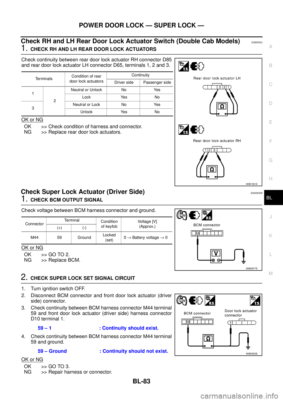
1.CHECK RH AND LH REAR DOOR LOCK ACTUATORS
Check continuity between rear door lock actuator RH connector D85
and rear door lock actuator LH connector D65, terminals 1, 2 and 3.
OK or NG
OK >> Check condition of harness and connector.
NG >> Replace rear door lock actuators.
Check Super Lock Actuator (Driver Side)EIS00DXM
1.CHECK BCM OUTPUT SIGNAL
Check voltage between BCM harness connector and ground.
OK or NG
OK >> GO TO 2.
NG >> Replace BCM.
2.CHECK SUPER LOCK SET SIGNAL CIRCUIT
1. Turn ignition switch OFF.
2. Disconnect BCM connector and front door lock actuator (driver
side) connector.
3. Check continuity between BCM harness connector M44 terminal
59 and front door lock actuator (driver side) harness connector
D10 terminal 1.
4. Check continuity between BCM harness connector M44 terminal
59 and ground.
OK or NG
OK >> GO TO 3.
NG >> Repair harness or connector.
Te r m i n a l sCondition of rear
door lock actuatorsContinuity
Driver side Passenger side
1
2Neutral or Unlock No Yes
Lock Yes No
3Neutral or Lock No Yes
Unlock Yes No
MIIB1061E
ConnectorTerminal
Condition
of keyfobVo l ta g e [V ]
(Approx.)
(+) (-)
M44 59 GroundLocked
(set)0®Battery voltage®0
MIIB0877E
59 – 1 : Continuity should exist.
59 – Ground : Continuity should not exist.
MIIB0802E
Page 675 of 3171

MULTI-REMOTE CONTROL SYSTEM
BL-91
C
D
E
F
G
H
J
K
L
MA
B
BL
System DescriptionEIS00DBE
INPUTS
Power is supplied at all times
lto BCM terminal 57
lthrough 50A fusible link (letterG, located in the fuse and fusible link box).
lto BCM terminal 41
lthrough 10A fuse [No. 21, located in the fuse block (J/B)].
When the key switch is ON (key is inserted in ignition key cylinder), power is supplied
lto BCM terminal 5
lthrough key switch terminals 2 and 1
lthrough 10A fuse [No. 22, located in the fuse block (J/B)].
When the ignition switch is ACC or ON, power is supplied
lto BCM terminal 4
lthrough 10A fuse [No. 4, located in the fuse block (J/B)].
When the ignition switch is ON or START, power is supplied
lto BCM terminal 3
lthrough 10A fuse [No. 1, located in the fuse block (J/B)].
When the front door switch (driver side) is ON (door is OPEN), ground is supplied
lto BCM terminal 15
lthrough front door switch (driver side) terminal 2
lto front door switch (driver side) case ground.
When the front door switch (passenger side) is ON (door is OPEN), ground is supplied
lto BCM terminal 14
lthrough front door switch (passenger side) terminal 2
lto front door switch (passenger side) case ground.
When the rear door switch LH is ON (door is OPEN), ground is supplied
lto BCM terminal 16
lthrough rear door switch LH terminal 2
lto rear door switch LH case ground.
When the rear door switch RH is ON (door is OPEN), ground is supplied
lto BCM terminal 12
lthrough rear door switch RH terminal 2
lto rear door switch RH case ground.
The multi-remote control system controls operation of the
lpowerdoorlock
linterior lamp and ignition keyhole illumination
lhazard reminder
lauto door lock operation
OPERATING PROCEDURE
Power Door Lock Operation
BCM receives a LOCK signal from keyfob. BCM locks all doors with input of LOCK signal from keyfob.
When an UNLOCK signal is sent from keyfob once, driver's door is unlocked.
Then, if an UNLOCK signal is sent from keyfob again within 5 seconds, all doors are unlocked.
Hazard Reminder
When the doors are locked or unlocked by keyfob, power is supplied to hazard warning lamp.
Hazard reminder does not operate if any door switches are ON (any doors are OPEN).
How to change hazard and horn reminder mode
Hazard and horn reminder can be changed using “WORK SUPPORT” mode in “MULTI ANSWER BACK SET”.
Refer toBL-102, "
CONSULT-II Function (BCM)".
Page 676 of 3171
BL-92
MULTI-REMOTE CONTROL SYSTEM
Auto Re-lock Function
The BCM is equipped with an auto re-lock function, when no further user action occurs after an full or partial
unlock, the doors will automatically re-lock after 2 minutes (default value).
The auto re-lock function will not be activated under the following state.
lKeyswitchisOn
lMechanical key is inserted
lAny door is opened
NOTE:
The 2 minutes timer of auto re-lock will be reset if unlock button from the key fob is pressed.
Auto relock function can be changed using “WORK SUPPORT” mode in “AUTO LOCK SET”.
Refer toBL-104, "
Work Support".
Room Lamp Operation
When the following conditions are met:
lcondition of room lamp switch is DOOR position;
ldoor switch OFF (when all the doors are closed);
With input of UNLOCK signal from keyfob multi-remote control system turns on interior lamp (for 30 seconds).
CAN Communication System DescriptionEIS00DBF
Refer toLAN-23, "CAN COMMUNICATION".
Page 687 of 3171

MULTI-REMOTE CONTROL SYSTEM
BL-103
C
D
E
F
G
H
J
K
L
MA
B
BL
6. Touch “MULTI REMOTE ENT”.
7. Select diagnosis mode.
“DATA MONITOR”, “ACTIVE TEST” and “WORK SUPPORT”
are available.
CONSULT-II Application ItemsEIS00DBL
“MULTI REMOTE ENT”
Data Monitor
Active Test
LIIA0194E
BCIA0031E
Monitored Item Description
DOOR SW-AS Indicates [ON/OFF] condition of front door switch passenger side.
DOOR SW-RR Indicates [ON/OFF] condition of rear door switch RH.
DOOR SW-RL Indicates [ON/OFF] condition of rear door switch LH.
DOOR SW-DR Indicates [ON/OFF] condition of front door switch driver side.
BACK DOOR SW Indicates [ON/OFF] condition of back door switch.
KEY ON SW Indicates [ON/OFF] condition of key switch.
ACC ON SW Indicates [ON/OFF] condition of ignition switch in ACC position.
IGN ON SW Indicates [ON/OFF] condition of ignition switch in ON position.
KEYLESS PANIC This is display even when it is not equipped.
KEYLESS UNLOCK Indicates [ON/OFF] condition of unlock signal from keyfob.
KEYLESS LOCK Indicates [ON/OFF] condition of lock signal from keyfob.
KEY CYL LK-SW Indicates [ON/OFF] condition of lock signal from door key cylinder switch.
CDL UNLOCK SW Indicates [ON/OFF] condition of unlock signal from lock/unlock switch.
CDL LOCK SW Indicates [ON/OFF] condition of lock signal from lock/unlock switch.
RKE LCK-UNLCK Indicates [ON/OFF] condition of lock/unlock signal at the same time from keyfob.
RKE KEEP UNLK Indicates [ON/OFF] condition of unlock signal from keyfob.
TRNK OPEN MNTR This is display even when it is not equipped.
Test Item Description
FLASHERThis test is able to check right and left hazard reminder operation. The right hazard lamp turns on
when “RH” on CONSULT-II screen is touched and the left hazard lamp turns on when "LH" on CON-
SULT-II screen is touched.
DOOR LOCKThis test is able to check door lock operation. The doors lock and unlock based on the item on CON-
SULT-II screen is touched.
Page 688 of 3171
BL-104
MULTI-REMOTE CONTROL SYSTEM
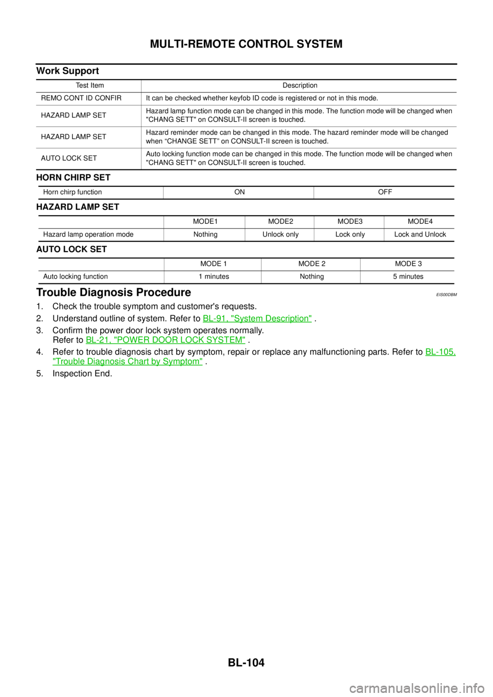
Work Support
HORN CHIRP SET
HAZARD LAMP SET
AUTO LOCK SET
Trouble Diagnosis ProcedureEIS00DBM
1. Check the trouble symptom and customer's requests.
2. Understand outline of system. Refer toBL-91, "
System Description".
3. Confirm the power door lock system operates normally.
Refer toBL-21, "
POWER DOOR LOCK SYSTEM".
4. Refer to trouble diagnosis chart by symptom, repair or replace any malfunctioning parts. Refer toBL-105,
"Trouble Diagnosis Chart by Symptom".
5. Inspection End.
Test Item Description
REMO CONT ID CONFIR It can be checked whether keyfob ID code is registered or not in this mode.
HAZARD LAMP SETHazard lamp function mode can be changed in this mode. The function mode will be changed when
"CHANG SETT" on CONSULT-II screen is touched.
HAZARD LAMP SETHazard reminder mode can be changed in this mode. The hazard reminder mode will be changed
when “CHANGE SETT” on CONSULT-II screen is touched.
AUTO LOCK SETAuto locking function mode can be changed in this mode. The function mode will be changed when
"CHANG SETT" on CONSULT-II screen is touched.
Horn chirp function ON OFF
MODE1 MODE2 MODE3 MODE4
Hazard lamp operation mode Nothing Unlock only Lock only Lock and Unlock
MODE 1 MODE 2 MODE 3
Auto locking function 1 minutes Nothing 5 minutes
Page 689 of 3171
MULTI-REMOTE CONTROL SYSTEM
BL-105
C
D
E
F
G
H
J
K
L
MA
B
BL
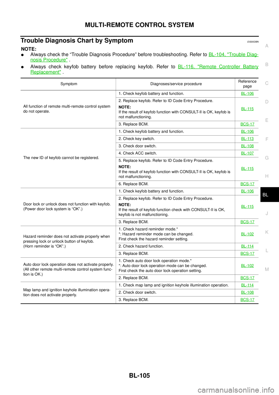
Trouble Diagnosis Chart by SymptomEIS00DBN
NOTE:
lAlways check the “Trouble Diagnosis Procedure” before troubleshooting. Refer toBL-104, "Trouble Diag-
nosis Procedure".
lAlways check keyfob battery before replacing keyfob. Refer toBL-116, "Remote Controller Battery
Replacement".
Symptom Diagnoses/service procedureReference
page
All function of remote multi-remote control system
do not operate.1. Check keyfob battery and function.BL-106
2. Replace keyfob. Refer to ID Code Entry Procedure.
NOTE:
If the result of keyfob function with CONSULT-II is OK, keyfob is
not malfunctioning.BL-115
3. Replace BCM.BCS-17
The new ID of keyfob cannot be registered.1. Check keyfob battery and function.BL-106
2. Check key switch.BL-113
3. Check door switch.BL-108
4. Check ACC switch.BL-107
5. Replace keyfob. Refer to ID Code Entry Procedure.
NOTE:
If the result of keyfob function with CONSULT-II is OK, keyfob is
not malfunctioning.BL-115
6. Replace BCM.BCS-17
Door lock or unlock does not function with keyfob.
(Power door lock system is “OK”.)1. Check keyfob battery and function.BL-106
2. Replace keyfob. Refer to ID Code Entry Procedure.
NOTE:
If the result of keyfob function check with CONSULT-II is OK,
keyfob is not malfunctioning.BL-115
3. Replace BCM.BCS-17
Hazard reminder does not activate properly when
pressing lock or unlock button of keyfob.
(Horn reminder is “OK”.)1. Check hazard reminder mode.*
*: Hazard reminder mode can be changed.
First check the hazard reminder setting.BL-102
2. Check hazard function.BL-114
3. Replace BCM.BCS-17
Auto door lock operation does not activate properly.
(All other remote multi-remote control system func-
tion is OK.)1. Check auto door lock operation mode.*
*: Auto door lock operation mode can be changed.
First check the auto door lock operation setting.BL-102
2. Replace BCM.BCS-17
Map lamp and ignition keyhole illumination opera-
tion does not activate properly.1. Check map lamp and ignition keyhole illumination operation.BL-1142. Check door switch.BL-108
3. Replace BCM.BCS-17
Page 690 of 3171

BL-106
MULTI-REMOTE CONTROL SYSTEM
Check Keyfob Battery and Function
EIS00DBO
1.CHECK KEYFOB BATTERY
1. Remove keyfob battery. Refer toBL-116, "
Remote Controller Battery Replacement".
2. Measure voltage between battery positive and negative termi-
nals, (+) and (-).
NOTE:
Keyfob does not function if battery is not set correctly.
OK or NG
OK >> GO TO 2.
NG >> Replace battery.
2.CHECK KEYFOB FUNCTION
With CONSULT-II
Check keyfob function in “DATA MONITOR” mode with CONSULT-II. When pushing each button of keyfob, the
corresponding monitor item should be turned as follows.
OK or NG
OK >> Keyfob is OK.
NG >> Replace keyfob.Voltage : 2.5 – 3.0V
SEL237W
Condition Monitor item
Pushing LOCK KEYLESS LOCK : ON
Pushing UNLOCK KEYLESS UNLOCK : ON
Press and hold UNLOCKRKE KEEP UNLK* : ON
*: Press and hold the unlock button for 3
seconds.
Pushing LOCK and UNLOCK at the
same timeRKE LCK-UNLOCK : ON
PIIA6468E
Page 699 of 3171
MULTI-REMOTE CONTROL SYSTEM
BL-115
C
D
E
F
G
H
J
K
L
MA
B
BL
ID Code Entry ProcedureEIS00DBU
KEYFOB ID SET UP
NOTE:
Keyfob ID setup procedure is same as ignition key registration (NATS initialization) procedure.
When the registration of the ignition key (NATS initialization) is performed with a NATS program card,
the registration of keyfob ID is done at the same time.
Regarding the procedures of NATS initialization and ignition key ID registration, refer to CONSULT-II
operation manual, NATS.
If additional key or key replacement is demanded, request all registed key fobs to be brought to the
dealer.
During the NATS initialization process, all registered key IDs will be deleted, thus, it is necessary to re-
register all keys.
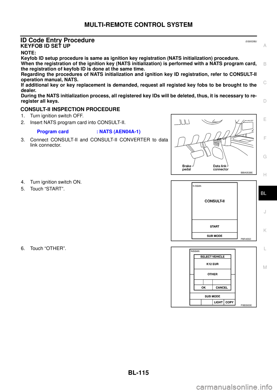
CONSULT-II INSPECTION PROCEDURE
1. Turn ignition switch OFF.
2. Insert NATS program card into CONSULT-II.
3. Connect CONSULT-II and CONSULT-II CONVERTER to data
link connector.
4. Turn ignition switch ON.
5. Touch “START”.
6. Touch “OTHER”.Program card : NATS (AEN04A-1)
BBIA0538E
PBR455D
PIIB0900E