2005 NISSAN NAVARA headlamp
[x] Cancel search: headlampPage 2550 of 3171
IPDM E/R (INTELLIGENT POWER DISTRIBUTION MODULE ENGINE ROOM)
PG-21
C
D
E
F
G
H
I
J
L
MA
B
PG
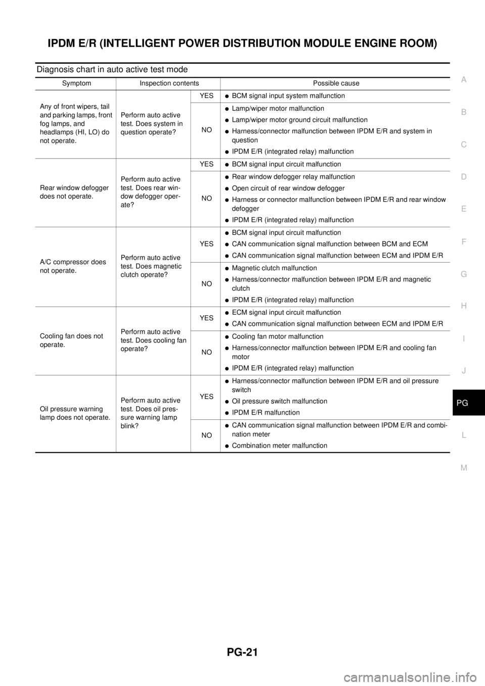
Diagnosis chart in auto active test mode
Symptom Inspection contents Possible cause
Any of front wipers, tail
and parking lamps, front
fog lamps, and
headlamps (HI, LO) do
not operate.Perform auto active
test. Does system in
question operate?YES
lBCM signal input system malfunction
NO
lLamp/wiper motor malfunction
lLamp/wiper motor ground circuit malfunction
lHarness/connector malfunction between IPDM E/R and system in
question
lIPDM E/R (integrated relay) malfunction
Rear window defogger
does not operate.Perform auto active
test. Does rear win-
dow defogger oper-
ate?YES
lBCM signal input circuit malfunction
NO
lRear window defogger relay malfunction
lOpen circuit of rear window defogger
lHarness or connector malfunction between IPDM E/R and rear window
defogger
lIPDM E/R (integrated relay) malfunction
A/C compressor does
not operate.Perform auto active
test. Does magnetic
clutch operate?YES
lBCM signal input circuit malfunction
lCAN communication signal malfunction between BCM and ECM
lCAN communication signal malfunction between ECM and IPDM E/R
NO
lMagnetic clutch malfunction
lHarness/connector malfunction between IPDM E/R and magnetic
clutch
lIPDM E/R (integrated relay) malfunction
Cooling fan does not
operate.Perform auto active
test. Does cooling fan
operate?YES
lECM signal input circuit malfunction
lCAN communication signal malfunction between ECM and IPDM E/R
NO
lCooling fan motor malfunction
lHarness/connector malfunction between IPDM E/R and cooling fan
motor
lIPDM E/R (integrated relay) malfunction
Oil pressure warning
lamp does not operate.Perform auto active
test. Does oil pres-
sure warning lamp
blink?YES
lHarness/connector malfunction between IPDM E/R and oil pressure
switch
lOil pressure switch malfunction
lIPDM E/R malfunction
NO
lCAN communication signal malfunction between IPDM E/R and combi-
nation meter
lCombination meter malfunction
Page 2597 of 3171

PG-68
HARNESS
Wiring Diagram Codes (Cell Codes)
EKS00LJ9
Use the chart below to find out what each wiring diagram code stands for.
Refer to the wiring diagram code in the alphabetical index to find the location (page number) of each wiring
diagram.
Code Section Wiring Diagram Name
A/C,A ATC Auto Air Conditioner
A/C,M MTC Manual Air Conditioner
ABS BRC Anti-lock Brake System
APP1PW EC Accelerator Pedal Position Sensor 1 Power
APP2PW EC Accelerator Pedal Position Sensor 2 Power
APPS1 EC Accelerator Pedal Position Sensor 1
APPS2 EC Accelerator Pedal Position Sensor 2
APPS3 EC Accelerator Pedal Position Sensor
ASC/BS EC ASCD Brake Switch
ASC/SW EC ASCD Steering Switch
ASCBOF EC ASCD Brake Switch
ASCIND EC ASCD Indicator
AT/IND DI A/T Indicator Lamp
AUDIO AV Audio
AUTO/L LT Auto Lignt System
BACK/L LT Back-up Lamp
BOOST EC Turbocharger Boost Sensor
CAN AT CAN Communication Line
CAN EC CAN Communication Line
CAN LAN CAN System
CHARGE SC Charging System
CHIME DI Warning Chime
CIGER WW Cigarette Lighter
CKPS EC Crankshaft Position Sensor
CMPS EC Camshaft Position Sensor
COMBSW LT Combination Switch
COMM AV Audio Visual Communication Line
COMPAS DI Compass
COOL/F EC Cooling Fan Control
D/LOCK BL Power Door Lock
DIFLOC RFD Rear Final Drive
DEF GW Rear Window Defogger
DTRL LT Headlamp — With Daytime Running Light System
ECMRLY EC ECM Relay
ECTS EC Engine Coolant Temperature Sensor
EGRVLV EC EGR Volume Control System
EMNT EC Electronic Controlled Engine Mount Control Solenoid Valve
F/FOG LT Front Fog Lamp
F/PUMP EC Fuel Pump
FRPS EC Fuel Rail Pressure Sensor
FTS AT A/T Fluid Temperature Sensor
Page 2598 of 3171
HARNESS
PG-69
C
D
E
F
G
H
I
J
L
MA
B
PG
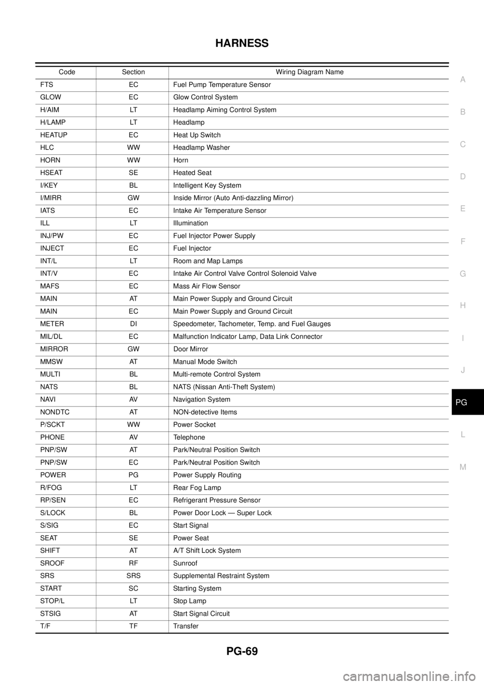
FTS EC Fuel Pump Temperature Sensor
GLOW EC Glow Control System
H/AIM LT Headlamp Aiming Control System
H/LAMP LT Headlamp
HEATUP EC Heat Up Switch
HLC WW Headlamp Washer
HORN WW Horn
HSEAT SE Heated Seat
I/KEY BL Intelligent Key System
I/MIRR GW Inside Mirror (Auto Anti-dazzling Mirror)
IATS EC Intake Air Temperature Sensor
ILL LT Illumination
INJ/PW EC Fuel Injector Power Supply
INJECT EC Fuel Injector
INT/L LT Room and Map Lamps
INT/V EC Intake Air Control Valve Control Solenoid Valve
MAFS EC Mass Air Flow Sensor
MAIN AT Main Power Supply and Ground Circuit
MAIN EC Main Power Supply and Ground Circuit
METER DI Speedometer, Tachometer, Temp. and Fuel Gauges
MIL/DL EC Malfunction Indicator Lamp, Data Link Connector
MIRROR GW Door Mirror
MMSW AT Manual Mode Switch
MULTI BL Multi-remote Control System
NATS BL NATS (Nissan Anti-Theft System)
NAVI AV Navigation System
NONDTC AT NON-detective Items
P/SCKT WW Power Socket
PHONE AV Telephone
PNP/SW AT Park/Neutral Position Switch
PNP/SW EC Park/Neutral Position Switch
POWER PG Power Supply Routing
R/FOG LT Rear Fog Lamp
RP/SEN EC Refrigerant Pressure Sensor
S/LOCK BL Power Door Lock — Super Lock
S/SIG EC Start Signal
SEAT SE Power Seat
SHIFT AT A/T Shift Lock System
SROOF RF Sunroof
SRS SRS Supplemental Restraint System
START SC Starting System
STOP/L LT Stop Lamp
STSIG AT Start Signal Circuit
T/F TF TransferCode Section Wiring Diagram Name
Page 2853 of 3171
SC-20
CHARGING SYSTEM
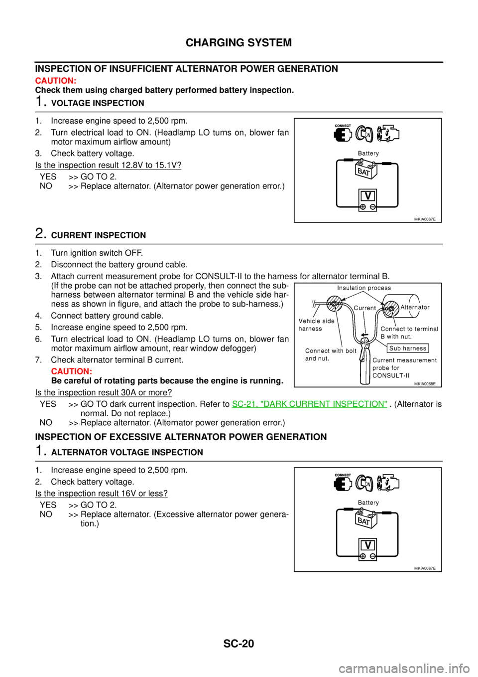
INSPECTION OF INSUFFICIENT ALTERNATOR POWER GENERATION
CAUTION:
Check them using charged battery performed battery inspection.
1.VOLTAGE INSPECTION
1. Increase engine speed to 2,500 rpm.
2. Turn electrical load to ON. (Headlamp LO turns on, blower fan
motor maximum airflow amount)
3. Check battery voltage.
Is the inspection result 12.8V to 15.1V?
YES >> GO TO 2.
NO >> Replace alternator. (Alternator power generation error.)
2.CURRENT INSPECTION
1. Turn ignition switch OFF.
2. Disconnect the battery ground cable.
3. Attach current measurement probe for CONSULT-II to the harness for alternator terminal B.
(If the probe can not be attached properly, then connect the sub-
harness between alternator terminal B and the vehicle side har-
ness as shown in figure, and attach the probe to sub-harness.)
4. Connect battery ground cable.
5. Increase engine speed to 2,500 rpm.
6. Turn electrical load to ON. (Headlamp LO turns on, blower fan
motor maximum airflow amount, rear window defogger)
7. Check alternator terminal B current.
CAUTION:
Be careful of rotating parts because the engine is running.
Is the inspection result 30A or more?
YES >> GO TO dark current inspection. Refer toSC-21, "DARK CURRENT INSPECTION". (Alternator is
normal. Do not replace.)
NO >> Replace alternator. (Alternator power generation error.)
INSPECTION OF EXCESSIVE ALTERNATOR POWER GENERATION
1.ALTERNATOR VOLTAGE INSPECTION
1. Increase engine speed to 2,500 rpm.
2. Check battery voltage.
Is the inspection result 16V or less?
YES >> GO TO 2.
NO >> Replace alternator. (Excessive alternator power genera-
tion.)
MKIA0067E
MKIA0068E
MKIA0067E
Page 3112 of 3171
WW-1
WIPER, WASHER & HORN
K ELECTRICAL
CONTENTS
C
D
E
F
G
H
I
J
L
M
SECTIONWW
A
B
WW
WIPER, WASHER & HORN
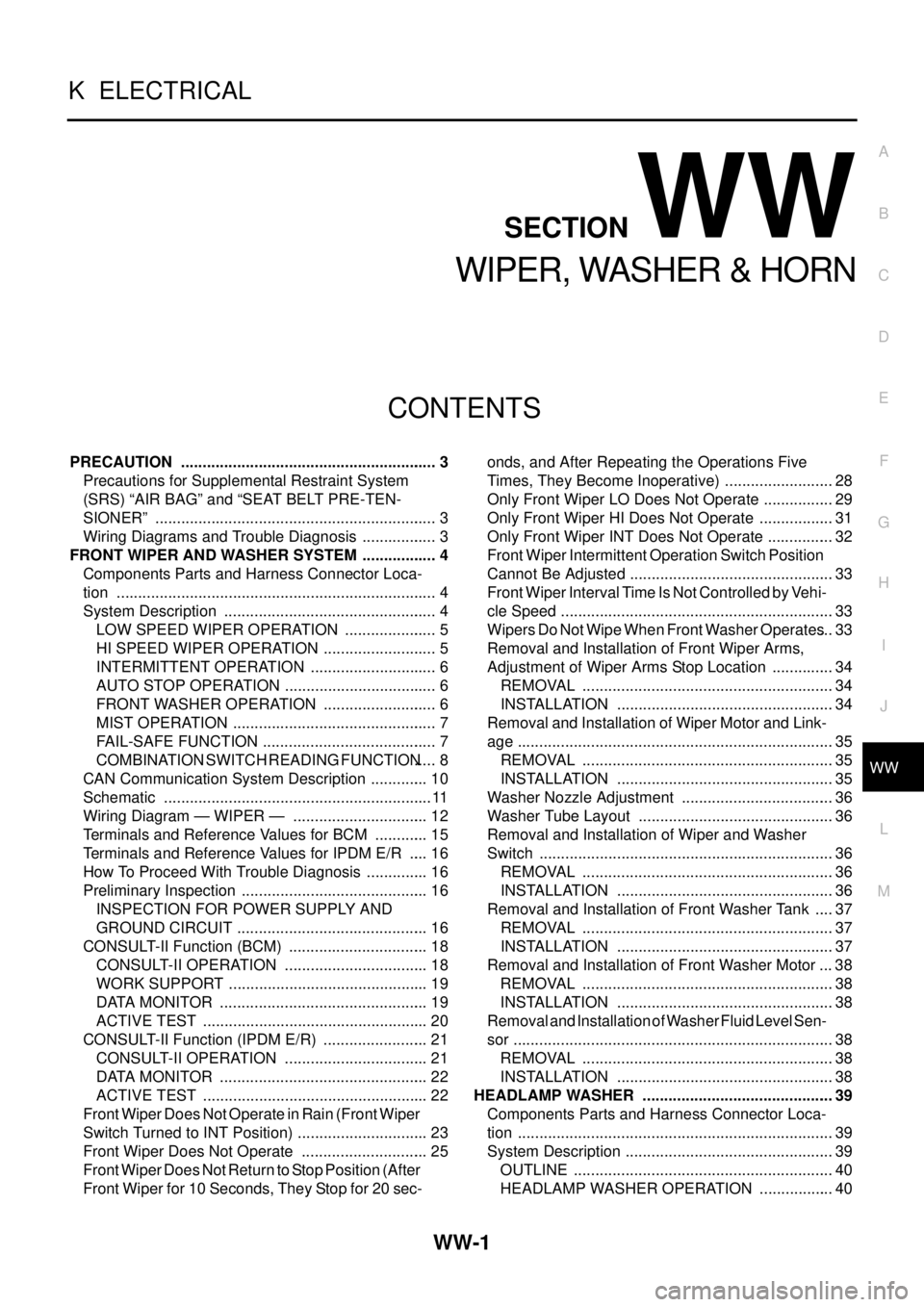
PRECAUTION ............................................................ 3
Precautions for Supplemental Restraint System
(SRS)“AIRBAG”and“SEATBELTPRE-TEN-
SIONER” .................................................................. 3
Wiring Diagrams and Trouble Diagnosis .................. 3
FRONT WIPER AND WASHER SYSTEM .................. 4
Components Parts and Harness Connector Loca-
tion ........................................................................... 4
System Description .................................................. 4
LOW SPEED WIPER OPERATION ...................... 5
HI SPEED WIPER OPERATION ........................... 5
INTERMITTENT OPERATION .............................. 6
AUTO STOP OPERATION .................................... 6
FRONT WASHER OPERATION ........................... 6
MIST OPERATION ................................................ 7
FAIL-SAFE FUNCTION ......................................... 7
COMBINATION SWITCH READING FUNCTION..... 8
CAN Communication System Description .............. 10
Schematic ............................................................... 11
Wiring Diagram — WIPER — ................................ 12
Terminals and Reference Values for BCM ............. 15
Terminals and Reference Values for IPDM E/R ..... 16
How To Proceed With Trouble Diagnosis ............... 16
Preliminary Inspection ............................................ 16
INSPECTION FOR POWER SUPPLY AND
GROUND CIRCUIT ............................................. 16
CONSULT-II Function (BCM) ................................. 18
CONSULT-II OPERATION .................................. 18
WORK SUPPORT ............................................... 19
DATA MONITOR ................................................. 19
ACTIVE TEST ..................................................... 20
CONSULT-II Function (IPDM E/R) ......................... 21
CONSULT-II OPERATION .................................. 21
DATA MONITOR ................................................. 22
ACTIVE TEST ..................................................... 22
Front Wiper Does Not Operate in Rain (Front Wiper
Switch Turned to INT Position) ............................... 23
Front Wiper Does Not Operate .............................. 25
Front Wiper Does Not Return to Stop Position (After
Front Wiper for 10 Seconds, They Stop for 20 sec-onds, and After Repeating the Operations Five
Times, They Become Inoperative) .......................... 28
Only Front Wiper LO Does Not Operate ................. 29
Only Front Wiper HI Does Not Operate .................. 31
Only Front Wiper INT Does Not Operate ................ 32
Front Wiper Intermittent Operation Switch Position
Cannot Be Adjusted ................................................ 33
Front Wiper Interval Time Is Not Controlled by Vehi-
cle Speed ................................................................ 33
Wipers Do Not Wipe When Front Washer Operates... 33
Removal and Installation of Front Wiper Arms,
Adjustment of Wiper Arms Stop Location ............... 34
REMOVAL ........................................................... 34
INSTALLATION ................................................... 34
Removal and Installation of Wiper Motor and Link-
age .......................................................................... 35
REMOVAL ........................................................... 35
INSTALLATION ................................................... 35
Washer Nozzle Adjustment .................................... 36
Washer Tube Layout .............................................. 36
Removal and Installation of Wiper and Washer
Switch ..................................................................... 36
REMOVAL ........................................................... 36
INSTALLATION ................................................... 36
Removal and Installation of Front Washer Tank ..... 37
REMOVAL ........................................................... 37
INSTALLATION ................................................... 37
Removal and Installation of Front Washer Motor ... 38
REMOVAL ........................................................... 38
INSTALLATION ................................................... 38
Removal and Installation of Washer Fluid Level Sen-
sor ........................................................................... 38
REMOVAL ........................................................... 38
INSTALLATION ................................................... 38
HEADLAMP WASHER ............................................. 39
Components Parts and Harness Connector Loca-
tion .......................................................................... 39
System Description ................................................. 39
OUTLINE ............................................................. 40
HEADLAMP WASHER OPERATION .................. 40
Page 3113 of 3171

WW-2
Wiring Diagram — HLC — ..................................... 41
Terminals and Reference Values for BCM .............. 43
Terminals and Reference Values for IPDM E/R ...... 43
How to Proceed with Trouble Diagnosis ................. 44
Preliminary Check .................................................. 44
CHECK POWER SUPPLY AND GROUND CIR-
CUIT .................................................................... 44
CONSULT-II Functions (BCM) ................................ 45
CONSULT-II BASIC OPERATION ....................... 45
DATA MONITOR .................................................. 46
ACTIVE TEST ..................................................... 47
CONSULT-II Functions (IPDM E/R) ........................ 48
CONSULT-II BASIC OPERATION ....................... 48
DATA MONITOR .................................................. 49
ACTIVE TEST ..................................................... 49
Headlamp Washer Does Not Operate .................... 50
Removal and Installation of Washer Nozzle ........... 53
REMOVAL ........................................................... 53
INSTALLATION .................................................... 53
Removal and Installation of Washer Tank .............. 53
Removal and Installation of Headlamp Washer
Motor ...................................................................... 53REMOVAL ............................................................ 53
INSTALLATION .................................................... 53
Washer Tube Layout ............................................... 54
CIGARETTE LIGHTER ............................................. 55
Wiring Diagram — CIGAR — .................................. 55
Removal and Installation of Cigarette Lighter ......... 56
REMOVAL ............................................................ 56
INSTALLATION .................................................... 56
POWER SOCKET ..................................................... 57
Wiring Diagram — P/SCKT — ................................ 57
Removal and Installation of Front Power Socket .... 58
REMOVAL ............................................................ 58
INSTALLATION .................................................... 58
Removal and Installation of Console Power Socket...58
REMOVAL ............................................................ 58
INSTALLATION .................................................... 58
HORN ........................................................................ 59
Wiring Diagram — HORN — .................................. 59
Removal and Installation of Horn ............................ 60
REMOVAL ............................................................ 60
INSTALLATION .................................................... 60
Page 3119 of 3171
WW-8
FRONT WIPER AND WASHER SYSTEM
COMBINATION SWITCH READING FUNCTION
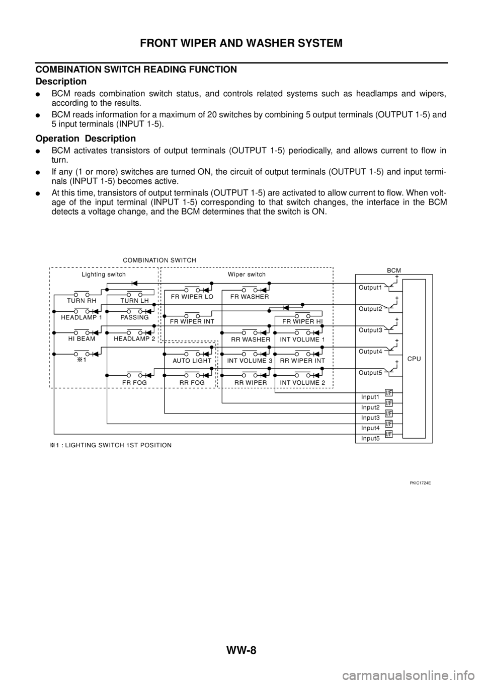
Description
lBCM reads combination switch status, and controls related systems such as headlamps and wipers,
according to the results.
lBCM reads information for a maximum of 20 switches by combining 5 output terminals (OUTPUT 1-5) and
5 input terminals (INPUT 1-5).
Operation Description
lBCM activates transistors of output terminals (OUTPUT 1-5) periodically, and allows current to flow in
turn.
lIf any (1 or more) switches are turned ON, the circuit of output terminals (OUTPUT 1-5) and input termi-
nals (INPUT 1-5) becomes active.
lAt this time, transistors of output terminals (OUTPUT 1-5) are activated to allow current to flow. When volt-
age of the input terminal (INPUT 1-5) corresponding to that switch changes, the interface in the BCM
detects a voltage change, and the BCM determines that the switch is ON.
PKIC1724E
Page 3148 of 3171
FRONT WIPER AND WASHER SYSTEM
WW-37
C
D
E
F
G
H
I
J
L
MA
B
WW
Removal and Installation of Front Washer TankEKS00P5J
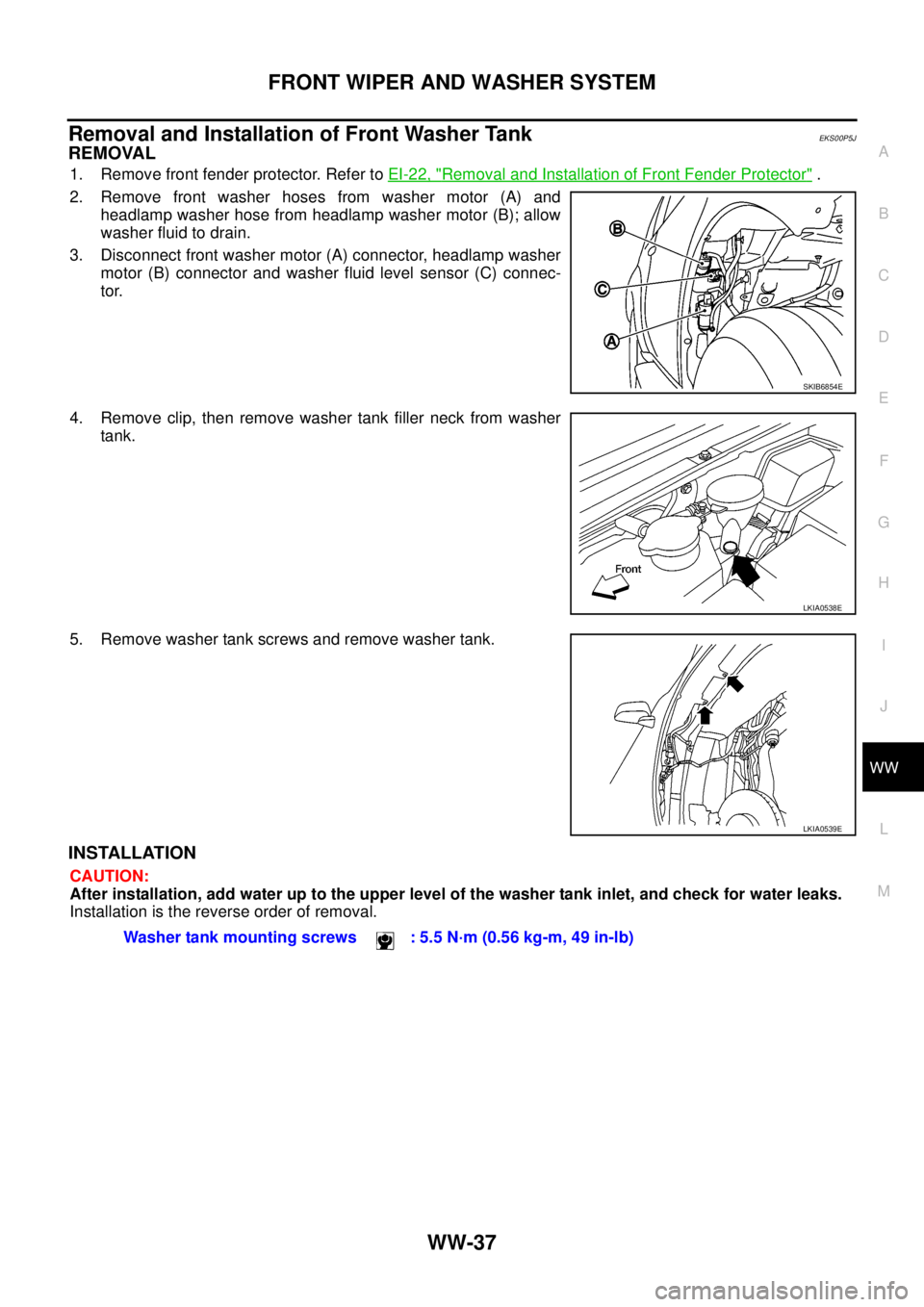
REMOVAL
1. Remove front fender protector. Refer toEI-22, "Removal and Installation of Front Fender Protector".
2. Remove front washer hoses from washer motor (A) and
headlamp washer hose from headlamp washer motor (B); allow
washer fluid to drain.
3. Disconnect front washer motor (A) connector, headlamp washer
motor (B) connector and washer fluid level sensor (C) connec-
tor.
4. Remove clip, then remove washer tank filler neck from washer
tank.
5. Remove washer tank screws and remove washer tank.
INSTALLATION
CAUTION:
After installation, add water up to the upper level of the washer tank inlet, and check for water leaks.
Installation is the reverse order of removal.
SKIB6854E
LKIA0538E
LKIA0539E
Washer tank mounting screws : 5.5 N·m (0.56 kg-m, 49 in-lb)