Page 3150 of 3171
HEADLAMP WASHER
WW-39
C
D
E
F
G
H
I
J
L
MA
B
WW
HEADLAMP WASHERPFP:28620
Components Parts and Harness Connector LocationEKS00P67
System DescriptionEKS00P68
Headlamp washer operates under the following conditions.
lWhen lighting switch is in 1ST position
lWhen daytime light system is operating
lWhen auto light system is operating (LOW beam is ON)
When the headlamp washer switch is ON position the BCM (body control module) receives input signal
requesting the headlamp washer operates. The CPU (central processing unit) of the IPDM E/R (intelligent
power distribution module engine room) controls the headlamp washer relay coil. When activated this relay
directs power headlamp washer motor.
SKIB6860E
Page 3151 of 3171

WW-40
HEADLAMP WASHER
OUTLINE
Power is supplied at all times
lto ignition relay (located in IPDM E/R), from battery directly,
lthrough 50A fusible link (letter G, located in fuse and fusible link box),
lto BCM terminal 57,
lthrough 20A fuse (No. 53, located in IPDM E/R)
lto CPU (central processing unit) (located in IPDM E/R).
With the ignition switch in the ON or START position, power is supplied
lto ignition relay (located in IPDM E/R),
lthrough 10A fuse [No. 1, located in fuse block (J/B)]
lto BCM terminal 3,
lthrough 10A fuse [No. 15, located in fuse block (J/B)]
lto combination switch terminal 2.
Ground is supplied
lto BCM terminal 55 and
lto combination switch terminal 9
lthrough grounds M21, M80 and M83,
lto IPDM E/R terminals 38 and 59
lthrough grounds E21, E41 and E61.
When the headlamp washer switch is ON, ground is supplied
lto BCM terminal 35
lthrough headlamp washer switch terminal 1
lthrough headlamp washer switch terminal 2
lthrough ground M21, M80 and M83.
HEADLAMP WASHER OPERATION
With the headlamp washer switch in the ON position, the BCM receives input signal requesting. This input sig-
nal is communicated to the IPDM E/R via the CAN communication. The CPU located in the IPDM E/R controls
the headlamp washer relay coil, which when energized, power is supplied
lthrough 10A fuse (No. 38, located in IPDM E/R)
lthrough IPDM E/R terminal 27
lto headlamp washer relay terminals 2 and 5,
lthrough headlamp washer relay terminal 1
lto IPDM E/R terminal 5,
lthrough headlamp washer relay terminal 3
lto headlamp washer motor terminal 1.
Ground is supplied
lto headlamp washer motor terminal 2
lthrough grounds E21, E41 and E61.
With power and ground supplied, headlamp washer operates.
Page 3152 of 3171
HEADLAMP WASHER
WW-41
C
D
E
F
G
H
I
J
L
MA
B
WW
Wiring Diagram — HLC —EKS00P69
MKWA3270E
Page 3153 of 3171
WW-42
HEADLAMP WASHER
MKWA3936E
Page 3154 of 3171

HEADLAMP WASHER
WW-43
C
D
E
F
G
H
I
J
L
MA
B
WW
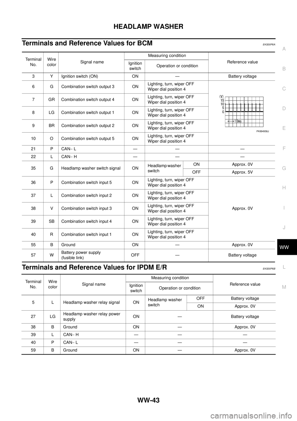
Terminals and Reference Values for BCMEKS00P6A
Terminals and Reference Values for IPDM E/REKS00P6B
Te r m i n a l
No.Wire
colorSignal nameMeasuring condition
Reference value
Ignition
switchOperation or condition
3 Y Ignition switch (ON) ON — Battery voltage
6 G Combination switch output 3 ONLighting, turn, wiper OFF
Wiper dial position 4
7 GR Combination switch output 4 ONLighting, turn, wiper OFF
Wiper dial position 4
8 LG Combination switch output 1 ONLighting, turn, wiper OFF
Wiper dial position 4
9 BR Combination switch output 2 ONLighting, turn, wiper OFF
Wiper dial position 4
10 O Combination switch output 5 ONLighting, turn, wiper OFF
Wiper dial position 4
21 P CAN-L—— —
22 L CAN-H—— —
35 G Headlamp washer switch signal ONHeadlamp washer
switchON Approx. 0V
OFF Approx. 5V
36 P Combination switch input 5 ONLighting, turn, wiper OFF
Wiper dial position 4
Approx. 0V 37 L Combination switch input 2 ONLighting, turn, wiper OFF
Wiper dial position 4
38 V Combination switch input 3 ONLighting, turn, wiper OFF
Wiper dial position 4
39 SB Combination switch input 4 ONLighting, turn, wiper OFF
Wiper dial position 4
40 R Combination switch input 1 ONLighting, turn, wiper OFF
Wiper dial position 4
55 B Ground ON — Approx. 0V
57 WBattery power supply
(fusible link)OFF — Battery voltage
PKIB4958J
Te r m i n a l
No.Wire
colorSignal nameMeasuring condition
Reference value
Ignition
switchOperation or condition
5 L Headlamp washer relay signal ONHeadlamp washer
switchOFF Battery voltage
ON Approx. 0V
27 LGHeadlamp washer relay power
supplyON — Battery voltage
38 B Ground ON — Approx. 0V
39 L CAN-H—— —
40 P CAN-L—— —
59 B Ground ON — Approx. 0V
Page 3155 of 3171

WW-44
HEADLAMP WASHER
How to Proceed with Trouble Diagnosis
EKS00P6C
1. Confirm the symptoms and customer complaint.
2. Understand operation description and function description. Refer toWW-39, "
System Description".
3. Perform the Preliminary Check. Refer toWW-44, "
Preliminary Check".
4. Check symptom and repair or replace the cause of malfunction.
5. Does headlamp washer operate normally? If YES, GO TO 6. If NO, GO TO 4.
6. INSPECTION END
Preliminary CheckEKS00P6D
CHECK POWER SUPPLY AND GROUND CIRCUIT
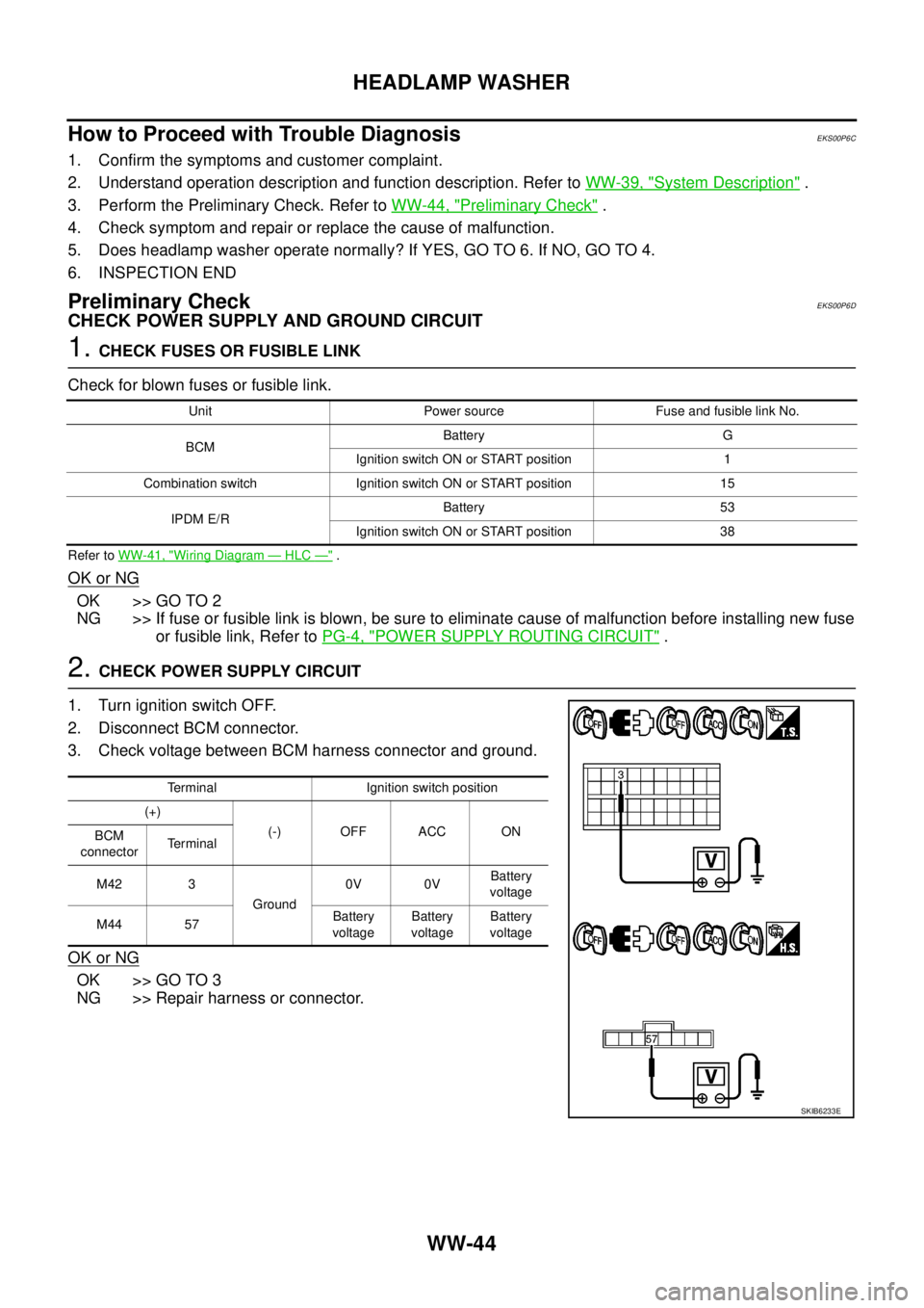
1.CHECK FUSES OR FUSIBLE LINK
Check for blown fuses or fusible link.
Refer toWW-41, "Wiring Diagram—HLC—".
OK or NG
OK >> GO TO 2
NG >> If fuse or fusible link is blown, be sure to eliminate cause of malfunction before installing new fuse
or fusible link, Refer toPG-4, "
POWER SUPPLY ROUTING CIRCUIT".
2.CHECK POWER SUPPLY CIRCUIT
1. Turn ignition switch OFF.
2. Disconnect BCM connector.
3. Check voltage between BCM harness connector and ground.
OK or NG
OK >> GO TO 3
NG >> Repair harness or connector.
Unit Power source Fuse and fusible link No.
BCMBattery G
Ignition switch ON or START position 1
Combination switch Ignition switch ON or START position 15
IPDM E/RBattery 53
Ignition switch ON or START position 38
Terminal Ignition switch position
(+)
(-) OFF ACC ON
BCM
connectorTerminal
M42 3
Ground0V 0VBattery
voltage
M44 57Battery
voltageBattery
voltageBattery
voltage
SKIB6233E
Page 3156 of 3171

HEADLAMP WASHER
WW-45
C
D
E
F
G
H
I
J
L
MA
B
WW
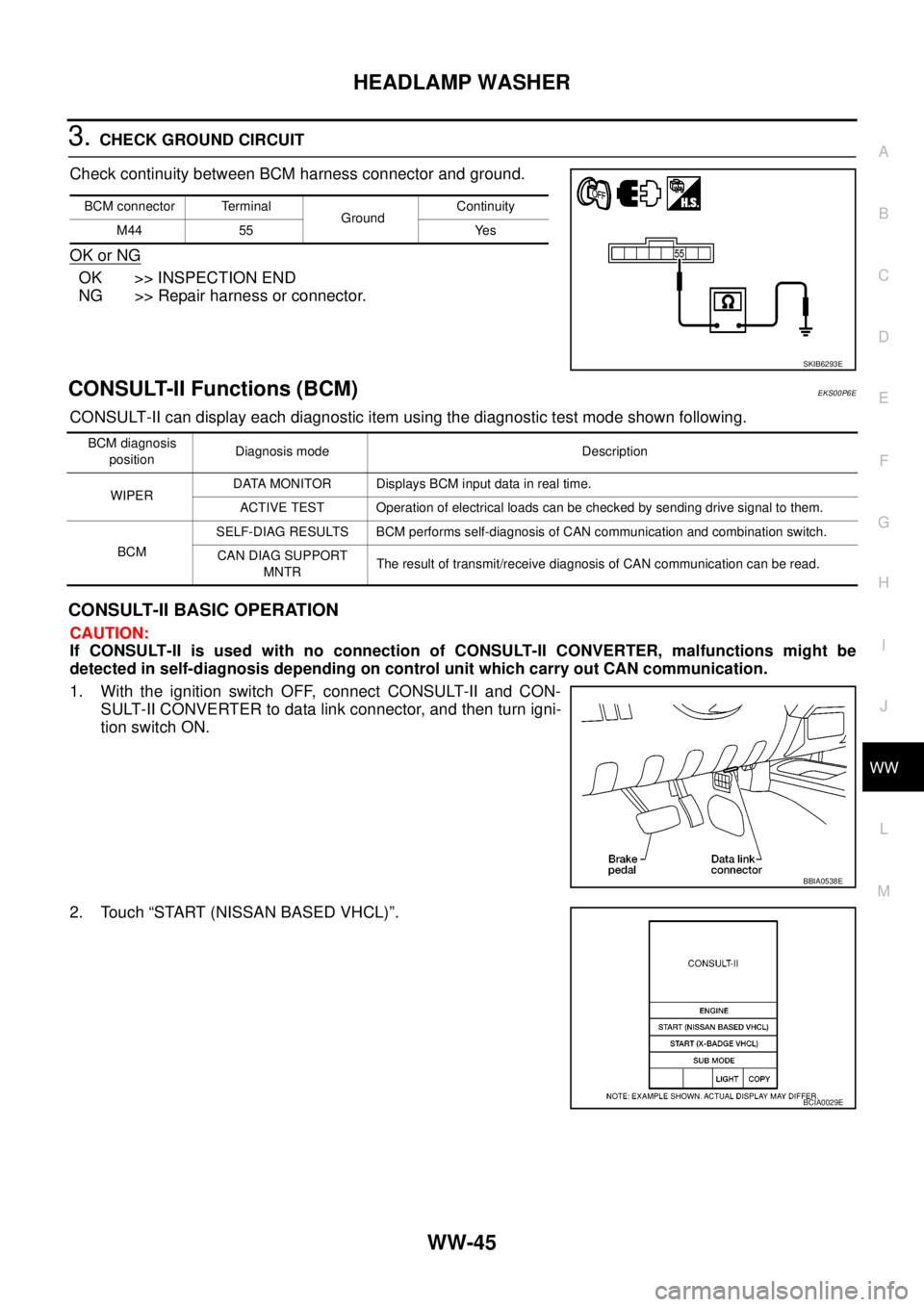
3.CHECK GROUND CIRCUIT
Check continuity between BCM harness connector and ground.
OK or NG
OK >> INSPECTION END
NG >> Repair harness or connector.
CONSULT-II Functions (BCM)EKS00P6E
CONSULT-II can display each diagnostic item using the diagnostic test mode shown following.
CONSULT-II BASIC OPERATION
CAUTION:
If CONSULT-II is used with no connection of CONSULT-II CONVERTER, malfunctions might be
detected in self-diagnosis depending on control unit which carry out CAN communication.
1. With the ignition switch OFF, connect CONSULT-II and CON-
SULT-II CONVERTER to data link connector, and then turn igni-
tion switch ON.
2. Touch “START (NISSAN BASED VHCL)”.
BCM connector Terminal
GroundContinuity
M44 55 Yes
SKIB6293E
BCM diagnosis
positionDiagnosis mode Description
WIPERDATA MONITOR Displays BCM input data in real time.
ACTIVE TEST Operation of electrical loads can be checked by sending drive signal to them.
BCMSELF-DIAG RESULTS BCM performs self-diagnosis of CAN communication and combination switch.
CAN DIAG SUPPORT
MNTRThe result of transmit/receive diagnosis of CAN communication can be read.
BBIA0538E
BCIA0029E
Page 3157 of 3171

WW-46
HEADLAMP WASHER
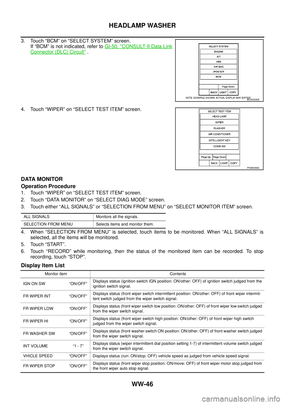
3. Touch “BCM” on “SELECT SYSTEM” screen.
If “BCM” is not indicated, refer toGI-50, "
CONSULT-II Data Link
Connector (DLC) Circuit".
4. Touch “WIPER” on “SELECT TEST ITEM” screen.
DATA MONITOR
Operation Procedure
1. Touch “WIPER” on “SELECT TEST ITEM” screen.
2. Touch “DATA MONITOR” on “SELECT DIAG MODE” screen.
3. Touch either “ALL SIGNALS” or “SELECTION FROM MENU” on “SELECT MONITOR ITEM” screen.
4. When “SELECTION FROM MENU” is selected, touch items to be monitored. When “ALL SIGNALS” is
selected, all the items will be monitored.
5. Touch “START”.
6. Touch “RECORD” while monitoring, then the status of the monitored item can be recorded. To stop
recording, touch “STOP”.
Display Item List
BCIA0030E
PKIB6096E
ALL SIGNALS Monitors all the signals.
SELECTION FROM MENU Selects items and monitor them.
Monitor item Contents
IGN ON SW “ON/OFF”Displays status (ignition switch IGN position: ON/other: OFF) of ignition switch judged from the
ignition switch signal.
FR WIPER INT “ON/OFF”Displays status (front wiper switch intermittent position: ON/other: OFF) of front wiper intermit-
tent switch judged from the wiper switch signal.
FR WIPER LOW “ON/OFF”Displays status (front wiper switch low position: ON/other: OFF) of front wiper low switch judged
from the wiper switch signal.
FR WIPER HI “ON/OFF”Displays status (front wiper switch high position: ON/other: OFF) of front wiper high switch
judged from the wiper switch signal.
FR WASHER SW “ON/OFF”Displays status (front washer switch ON position: ON/other: OFF) of front washer switch judged
from the wiper switch signal.
INT VOLUME “1 - 7”Displays status (wiper intermittent dial position setting 1-7) of intermittent volume switch judged
from the wiper switch signal.
VHICLE SPEED “ON/OFF” Displays status (run: ON/stop: OFF) vehicle speed as judged from vehicle speed signal.
FR WIPER STOP “ON/OFF”Displays status (front wiper stop position: ON/move: OFF) of front wiper motor stop judged from
the front wiper auto stop signal.