Page 2144 of 3171

AUTO LIGHT SYSTEM
LT-61
C
D
E
F
G
H
I
J
L
MA
B
LT
Display Item List
NOTE:
This item is displayed, but cannot be monitored.
ACTIVE TEST
Operation Procedure
1. Touch “HEAD LAMP” on “SELECT TEST ITEM” screen.
2. Touch “ACTIVE TEST” on “SELECT DIAG MODE” screen.
3. Touch item to be tested and check operation of the selected item.
4. During the operation check, touching “OFF” deactivates the operation.
Display Item List
Monitor item Contents
IGN ON SW “ON/OFF”Displays status (ignition switch IGN position: ON/other: OFF) of ignition switch judged from
the ignition switch signal.
ACC ON SW “ON/OFF”Displays status (ignition switch ACC or IGN position: ON/other: OFF) of ignition switch judged
from the ignition switch signal.
HI BEAM SW “ON/OFF”Displays status (lighting switch high beam position: ON/other: OFF) of high beam switch
judged from the lighting switch signal.
HEAD LAMP SW 1 “ON/OFF”Displays status (lighting switch 2ND position: ON/other: OFF) of headlamp 1 switch judged
from the lighting switch signal.
HEAD LAMP SW 2 “ON/OFF”Displays status (lighting switch 2ND position: ON/other: OFF) of headlamp 2 switch judged
from the lighting switch signal.
LIGHT SW 1ST “ON/OFF”Displays status (lighting switch 1ST or 2ND position: ON/other: OFF) of lighting switch 1ST
position switch judged from the lighting switch signal.
PASSING SW “ON/OFF”Displays status (lighting switch passing position: ON/other: OFF) of passing switch judged
from the lighting switch signal.
FR FOG SW “ON/OFF”Displays status (lighting switch front fog lamp ON position: ON/others: OFF) of front fog lamp
switch judged from the lighting switch signal.
RR FOG SW “ON/OFF”Displays status (lighting switch rear fog lamp ON position: ON/others: OFF) of rear fog lamp
switch judged from the lighting switch signal.
DOOR SW - DR “ON/OFF”Displays status (door is open: ON/door is closed: OFF) of driver side door switch judged from
the driver side door switch signal.
DOOR SW - AS “ON/OFF”Displays status (door is open: ON/door is closed: OFF) of passenger side door switch judged
from the passenger side door switch signal.
DOOR SW - RR “ON/OFF”Displays status (door is open: ON/door is closed: OFF) of rear door switch (RH) judged from
the rear door switch (RH) signal.
DOOR SW - RL “ON/OFF”Displays status (door is open: ON/door is closed: OFF) of rear door switch (LH) judged from
the rear door switch (LH) signal.
BACK DOOR SW “ON/OFF”Displays status (door is open: ON/door is closed: OFF) of back door switch judged from the
back door switch signal.
TURN SIGNAL R “ON/OFF”Displays status (turn signal switch right position: ON/other: OFF) of turn RH switch judged
from the turn signal switch signal.
TURN SIGNAL L “ON/OFF”Displays status (turn signal switch left position: ON/other: OFF) of turn LH switch judged from
the turn signal switch signal.
CARGO LAMP SW
NOTE“OFF” —
HD LIGHT TIMER“10 sec/
30 sec”Displays status (MODE 1: 10 sec./ MODE 2: 30 sec.) of head light timer.
LIT-SEN FAIL
NOTE“OK” —
AUT LIGHT SYS
NOTE“OFF” —
Test item Description
TAIL LAMP Allows tail lamp relay to operate by switching ON-OFF.
HEAD LAMP Allows headlamp relay (HI, LO) to operate by switching ON-OFF.
Page 2145 of 3171

LT-62
AUTO LIGHT SYSTEM
Trouble Diagnosis Chart by Symptom
EKS00Q86
Lighting Switch InspectionEKS00Q87
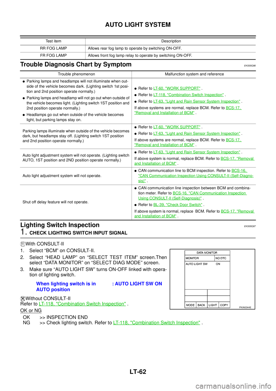
1.CHECK LIGHTING SWITCH INPUT SIGNAL
With CONSULT-II
1. Select “BCM” on CONSULT-II.
2. Select “HEAD LAMP” on “SELECT TEST ITEM” screen.Then
select “DATA MONITOR” on “SELECT DIAG MODE” screen.
3. Make sure “AUTO LIGHT SW” turns ON-OFF linked with opera-
tion of lighting switch.
Without CONSULT-II
Refer toLT- 11 8 , "
Combination Switch Inspection".
OK or NG
OK >> INSPECTION END
NG >> Check lighting switch. Refer toLT- 11 8 , "
Combination Switch Inspection".
RR FOG LAMP Allows rear fog lamp to operate by switching ON-OFF.
FR FOG LAMP Allows front fog lamp relay to operate by switching ON-OFF.Test item Description
Trouble phenomenon Malfunction system and reference
lParking lamps and headlamps will not illuminate when out-
side of the vehicle becomes dark. (Lighting switch 1st posi-
tion and 2nd position operate normally.)
lParking lamps and headlamp will not go out when outside of
the vehicle becomes light. (Lighting switch 1ST position and
2nd position operate normally.)
lHeadlamps go out when outside of the vehicle becomes
light, but parking lamps stay on.
lRefer toLT- 6 0 , "WORK SUPPORT".
lRefer toLT- 11 8 , "Combination Switch Inspection".
lRefer toLT- 6 3 , "Light and Rain Sensor System Inspection".
If above systems are normal, replace BCM. Refer toBCS-17,
"Removal and Installation of BCM".
Parking lamps illuminate when outside of the vehicle becomes
dark, but headlamps stay off. (Lighting switch 1ST position
and 2nd position operate normally.)
lRefer toLT- 6 0 , "WORK SUPPORT".
lRefer toLT- 6 3 , "Light and Rain Sensor System Inspection".
If above systems are normal, replace BCM. Refer toBCS-17,
"Removal and Installation of BCM".
Auto light adjustment system will not operate. (Lighting switch
AUTO, 1ST position and 2ND position operate normally.)
lRefer toLT- 6 3 , "Light and Rain Sensor System Inspection".
If above system is normal, replace BCM. Refer toBCS-17, "
Removal
and Installation of BCM".
Auto light adjustment system will not operate.
lCAN communication line to BCM inspection. Refer toBCS-16,
"CAN Communication Inspection Using CONSULT-II (Self-Diagno-
sis)".
Shut off delay feature will not operate.
lCAN communication line inspection between BCM and combina-
tion meter. Refer toBCS-16, "
CAN Communication Inspection
Using CONSULT-II (Self-Diagnosis)".
lRefer toBL-39, "Check Door Switch".
If above system is normal, replace BCM. Refer toBCS-17, "
Removal
and Installation of BCM".
When lighting switch is in
AUTO position: AUTO LIGHT SW ON
PKIA6344E
Page 2149 of 3171
LT-66
HEADLAMP AIMING CONTROL (MANUAL)
HEADLAMP AIMING CONTROL (MANUAL)
PFP:25190
SchematicEKS00P39
MKWA3668E
Page 2150 of 3171
HEADLAMP AIMING CONTROL (MANUAL)
LT-67
C
D
E
F
G
H
I
J
L
MA
B
LT
Wiring Diagram — H/AIM —EKS00PCK
MKWA3566E
Page 2151 of 3171
LT-68
HEADLAMP AIMING CONTROL (MANUAL)
MKWA3567E
Page 2152 of 3171
HEADLAMP AIMING CONTROL (MANUAL)
LT-69
C
D
E
F
G
H
I
J
L
MA
B
LT
MKWA3568E
Page 2153 of 3171
LT-70
HEADLAMP AIMING CONTROL (MANUAL)
Removal and Installation
EKS00P3A
1. Remove lower instrument panel (driver side) (1). Refer toIP-10,
"Removal and Installation".
2. Press headlamp aiming switch (2) fixing pawl (A) and remove
unit from instrument lower panel (driver side) (1).
Switch Circuit InspectionEKS00P3B
Using a circuit tester, check resistance between headlamp aiming
switch connector terminals in each operation status of aiming switch.
SKIB6853E
PKIC0552E
Page 2154 of 3171

FRONT FOG LAMP
LT-71
C
D
E
F
G
H
I
J
L
MA
B
LT
FRONT FOG LAMPPFP:26150
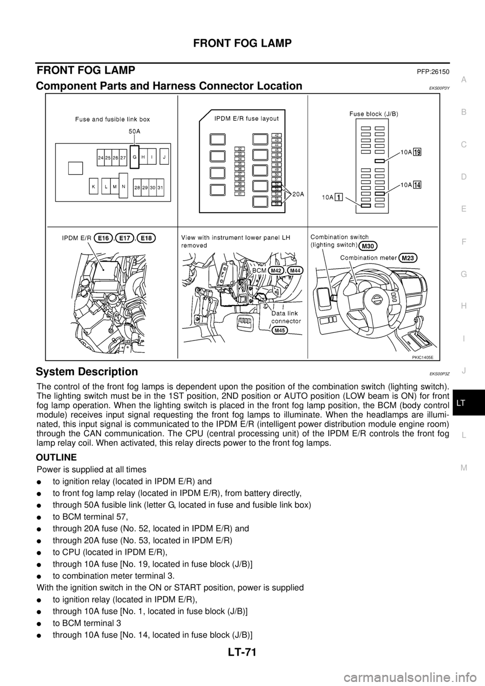
Component Parts and Harness Connector LocationEKS00P3Y
System DescriptionEKS00P3Z
The control of the front fog lamps is dependent upon the position of the combination switch (lighting switch).
The lighting switch must be in the 1ST position, 2ND position or AUTO position (LOW beam is ON) for front
fog lamp operation. When the lighting switch is placed in the front fog lamp position, the BCM (body control
module) receives input signal requesting the front fog lamps to illuminate. When the headlamps are illumi-
nated, this input signal is communicated to the IPDM E/R (intelligent power distribution module engine room)
through the CAN communication. The CPU (central processing unit) of the IPDM E/R controls the front fog
lamp relay coil. When activated, this relay directs power to the front fog lamps.
OUTLINE
Power is supplied at all times
lto ignition relay (located in IPDM E/R) and
lto front fog lamp relay (located in IPDM E/R), from battery directly,
lthrough 50A fusible link (letter G, located in fuse and fusible link box)
lto BCM terminal 57,
lthrough 20A fuse (No. 52, located in IPDM E/R) and
lthrough 20A fuse (No. 53, located in IPDM E/R)
lto CPU (located in IPDM E/R),
lthrough 10A fuse [No. 19, located in fuse block (J/B)]
lto combination meter terminal 3.
With the ignition switch in the ON or START position, power is supplied
lto ignition relay (located in IPDM E/R),
lthrough 10A fuse [No. 1, located in fuse block (J/B)]
lto BCM terminal 3
lthrough 10A fuse [No. 14, located in fuse block (J/B)]
PKIC1405E