2005 NISSAN NAVARA headlamp
[x] Cancel search: headlampPage 2168 of 3171
FRONT FOG LAMP
LT-85
C
D
E
F
G
H
I
J
L
MA
B
LT
Aiming AdjustmentEKS00P4D
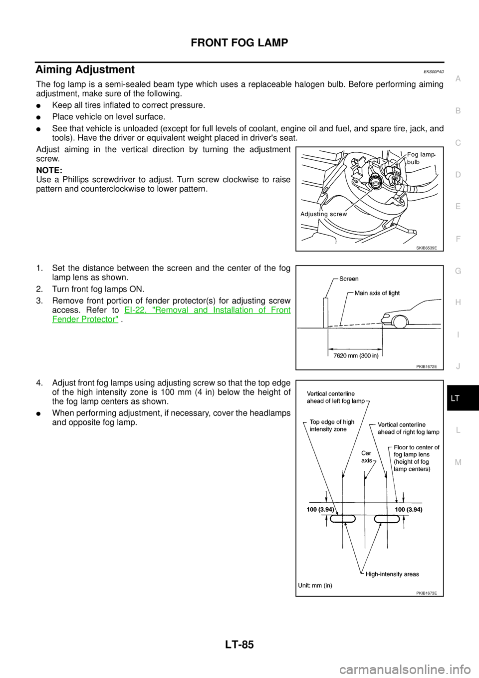
The fog lamp is a semi-sealed beam type which uses a replaceable halogen bulb. Before performing aiming
adjustment, make sure of the following.
lKeep all tires inflated to correct pressure.
lPlace vehicle on level surface.
lSee that vehicle is unloaded (except for full levels of coolant, engine oil and fuel, and spare tire, jack, and
tools). Have the driver or equivalent weight placed in driver's seat.
Adjust aiming in the vertical direction by turning the adjustment
screw.
NOTE:
Use a Phillips screwdriver to adjust. Turn screw clockwise to raise
pattern and counterclockwise to lower pattern.
1. Set the distance between the screen and the center of the fog
lamp lens as shown.
2. Turn front fog lamps ON.
3. Remove front portion of fender protector(s) for adjusting screw
access. Refer toEI-22, "
Removal and Installation of Front
Fender Protector".
4. Adjust front fog lamps using adjusting screw so that the top edge
of the high intensity zone is 100 mm (4 in) below the height of
the fog lamp centers as shown.
lWhen performing adjustment, if necessary, cover the headlamps
and opposite fog lamp.
SKIB6539E
PKIB1672E
PKIB1673E
Page 2169 of 3171
LT-86
FRONT FOG LAMP
Bulb Replacement
EKS00P4E
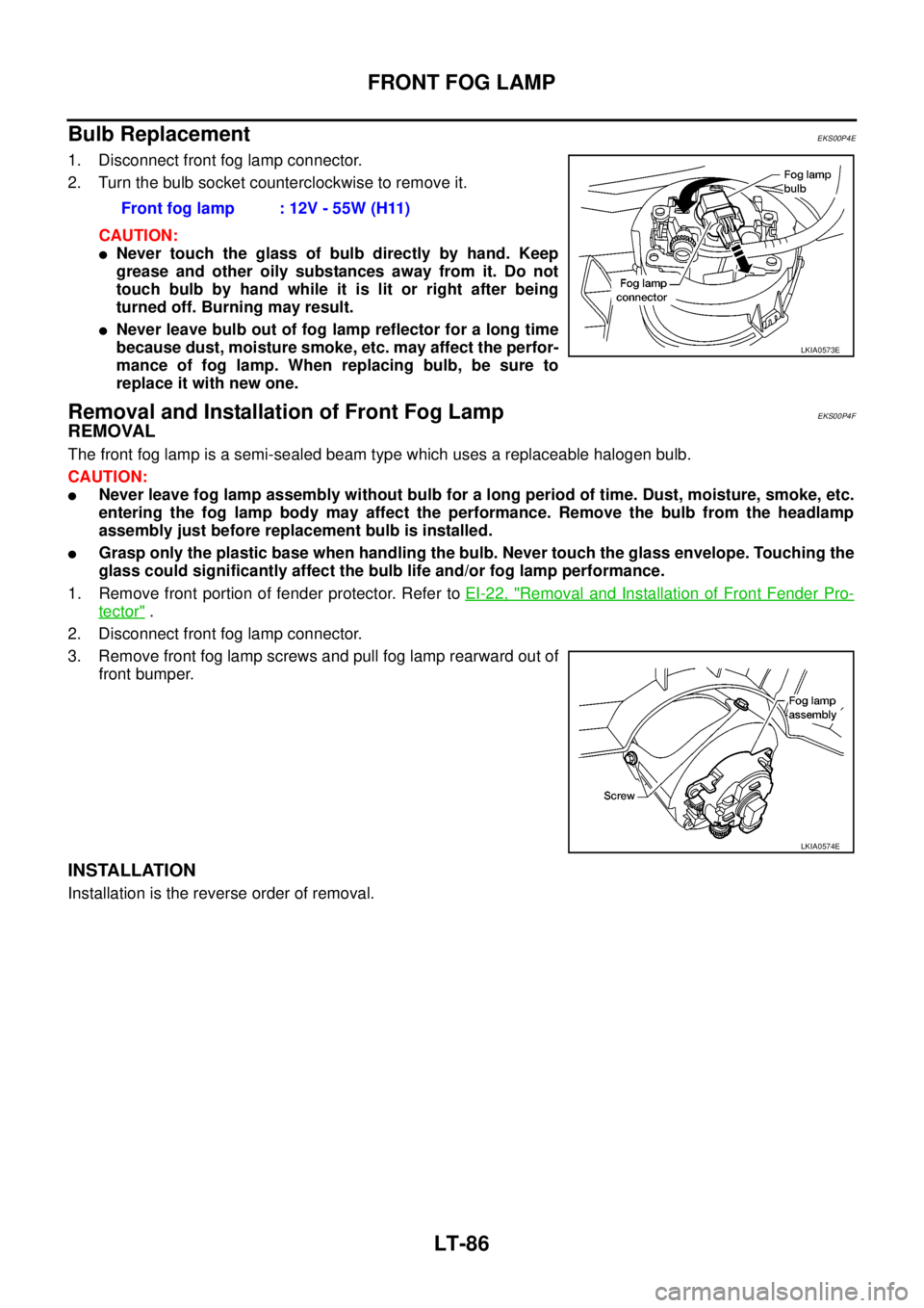
1. Disconnect front fog lamp connector.
2. Turn the bulb socket counterclockwise to remove it.
CAUTION:
lNever touch the glass of bulb directly by hand. Keep
grease and other oily substances away from it. Do not
touch bulb by hand while it is lit or right after being
turned off. Burning may result.
lNever leave bulb out of fog lamp reflector for a long time
because dust, moisture smoke, etc. may affect the perfor-
mance of fog lamp. When replacing bulb, be sure to
replace it with new one.
Removal and Installation of Front Fog LampEKS00P4F
REMOVAL
The front fog lamp is a semi-sealed beam type which uses a replaceable halogen bulb.
CAUTION:
lNever leave fog lamp assembly without bulb for a long period of time. Dust, moisture, smoke, etc.
entering the fog lamp body may affect the performance. Remove the bulb from the headlamp
assembly just before replacement bulb is installed.
lGrasp only the plastic base when handling the bulb. Never touch the glass envelope. Touching the
glass could significantly affect the bulb life and/or fog lamp performance.
1. Remove front portion of fender protector. Refer toEI-22, "
Removal and Installation of Front Fender Pro-
tector".
2. Disconnect front fog lamp connector.
3. Remove front fog lamp screws and pull fog lamp rearward out of
front bumper.
INSTALLATION
Installation is the reverse order of removal.Front fog lamp : 12V - 55W (H11)
LKIA0573E
LKIA0574E
Page 2179 of 3171
LT-96
REAR FOG LAMP
RearFogLampDoesNotTurnOFF
EKS00P4R
1.CHECK CIRCUIT BETWEEN COMBINATION SWITCH AND BCM
With CONSULT-II
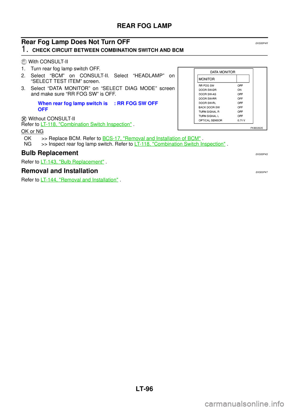
1. Turn rear fog lamp switch OFF.
2. Select “BCM” on CONSULT-II. Select “HEADLAMP” on
“SELECT TEST ITEM” screen.
3. Select “DATA MONITOR” on “SELECT DIAG MODE” screen
andmakesure“RRFOGSW”isOFF.
Without CONSULT-II
Refer toLT- 11 8 , "
Combination Switch Inspection".
OK or NG
OK >> Replace BCM. Refer toBCS-17, "Removal and Installation of BCM".
NG >> Inspect rear fog lamp switch. Refer toLT- 11 8 , "
Combination Switch Inspection".
Bulb ReplacementEKS00P4S
Refer toLT- 1 4 3 , "Bulb Replacement".
Removal and InstallationEKS00P4T
Refer toLT- 1 4 4 , "Removal and Installation". When rear fog lamp switch is
OFF: RR FOG SW OFF
PKIB0262E
Page 2199 of 3171

LT-116
COMBINATION SWITCH
4. Touch “COMB SW” on “SELECT TEST ITEM” screen.
DATA MONITOR
Operation Procedure
1. Touch “COMB SW” on “SELECT TEST ITEM” screen.
2. Touch “DATA MONITOR” on “SELECT DIAG MODE” screen.
3. Touch either “ALL SIGNALS” or “SELECTION FROM MENU” on “SELECT MONITOR ITEM” screen.
4. When “ALL SIGNALS” is selected, all the signals will be monitored. When “SELECTION FROM MENU” is
selected, touch items to be monitored.
5. Touch “START”.
6. Touch “RECORD” while monitoring, then the status of the monitored item can be recorded. To stop
recording, touch “STOP”.
Display Item List
PKIB6096E
ALL SIGNALS Monitors all the signals.
SELECTION FROM MENU Selects and monitors individual signal.
Monitor item Contents
TURN SIGNAL R “ON/OFF”Displays status (turn signal switch right position: ON/other: OFF) of turn RH switch judged from the
turn signal switch signal.
TURN SIGNAL L “ON/OFF”Displays status (turn signal switch left position: ON/other: OFF) of turn LH switch judged from the
turn signal switch signal.
HI BEAM SW “ON/OFF”Displays status (lighting switch high beam position: ON/other: OFF) of high beam switch judged
from the lighting switch signal.
HEAD LAMP SW 1 “ON/OFF”Displays status (lighting switch 2ND position: ON/other: OFF) of headlamp 1 switch judged from
the lighting switch signal.
HEAD LAMP SW 2 “ON/OFF”Displays status (lighting switch 2ND position: ON/other: OFF) of headlamp 2 switch judged from
the lighting switch signal.
LIGHT SW 1ST “ON/OFF”Displays status (lighting switch 1ST or 2ND position: ON/other: OFF) of lighting switch 1ST position
switch judged from the lighting switch signal.
PASSING SW “ON/OFF”Displays status (lighting switch passing position: ON/other: OFF) of passing switch judged from the
lighting switch signal.
FR FOG SW “ON/OFF”Displays status (lighting switch front fog lamp ON position: ON/others: OFF) of front fog lamp
switch judged from the lighting switch signal.
RR FOG SW “ON/OFF”Displays status (rear fog lamp switch position: ON/other: OFF) of rear fog switch judged from the
lighting switch signal.
FR WIPER HI “ON/OFF”Displays status (front wiper switch high position: ON/other: OFF) of front wiper high switch judged
from the wiper switch signal.
FR WIPER LOW “ON/OFF”Displays status (front wiper switch low position: ON/other: OFF) of front wiper low switch judged
from the wiper switch signal.
FR WIPER INT “ON/OFF”Displays status (front wiper switch intermittent position: ON/other: OFF) of front wiper intermittent
switch judged from the wiper switch signal.
FR WASHER SW “ON/OFF”Displays status (front washer switch ON position: ON/other: OFF) of front washer switch judged
from the wiper switch signal.
Page 2221 of 3171
LT-138
PARKING, LICENSE PLATE AND TAIL LAMPS
Clarence, License Plate and Tail Lamps Do Not Illuminate
EKS00P9Q
1.CHECK COMBINATION SWITCH INPUT SIGNAL
With CONSULT-II
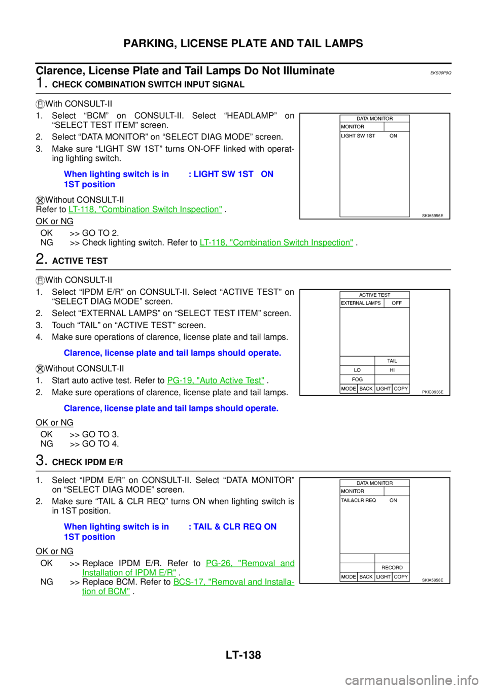
1. Select “BCM” on CONSULT-II. Select “HEADLAMP” on
“SELECT TEST ITEM” screen.
2. Select “DATA MONITOR” on “SELECT DIAG MODE” screen.
3. Make sure “LIGHT SW 1ST” turns ON-OFF linked with operat-
ing lighting switch.
Without CONSULT-II
Refer toLT- 11 8 , "
Combination Switch Inspection".
OK or NG
OK >> GO TO 2.
NG >> Check lighting switch. Refer toLT- 11 8 , "
Combination Switch Inspection".
2.ACTIVE TEST
With CONSULT-II
1. Select “IPDM E/R” on CONSULT-II. Select “ACTIVE TEST” on
“SELECT DIAG MODE” screen.
2. Select “EXTERNAL LAMPS” on “SELECT TEST ITEM” screen.
3. Touch “TAIL” on “ACTIVE TEST” screen.
4. Make sure operations of clarence, license plate and tail lamps.
Without CONSULT-II
1. Start auto active test. Refer toPG-19, "
Auto Active Test".
2. Make sure operations of clarence, license plate and tail lamps.
OK or NG
OK >> GO TO 3.
NG >> GO TO 4.
3.CHECK IPDM E/R
1. Select “IPDM E/R” on CONSULT-II. Select “DATA MONITOR”
on “SELECT DIAG MODE” screen.
2. Make sure “TAIL & CLR REQ” turns ON when lighting switch is
in 1ST position.
OK or NG
OK >> Replace IPDM E/R. Refer toPG-26, "Removal and
Installation of IPDM E/R".
NG >> Replace BCM. Refer toBCS-17, "
Removal and Installa-
tion of BCM". When lighting switch is in
1ST position: LIGHT SW 1ST ON
SKIA5956E
Clarence, license plate and tail lamps should operate.
Clarence, license plate and tail lamps should operate.
PKIC0936E
When lighting switch is in
1ST position: TAIL & CLR REQ ON
SKIA5958E
Page 2224 of 3171
PARKING, LICENSE PLATE AND TAIL LAMPS
LT-141
C
D
E
F
G
H
I
J
L
MA
B
LT
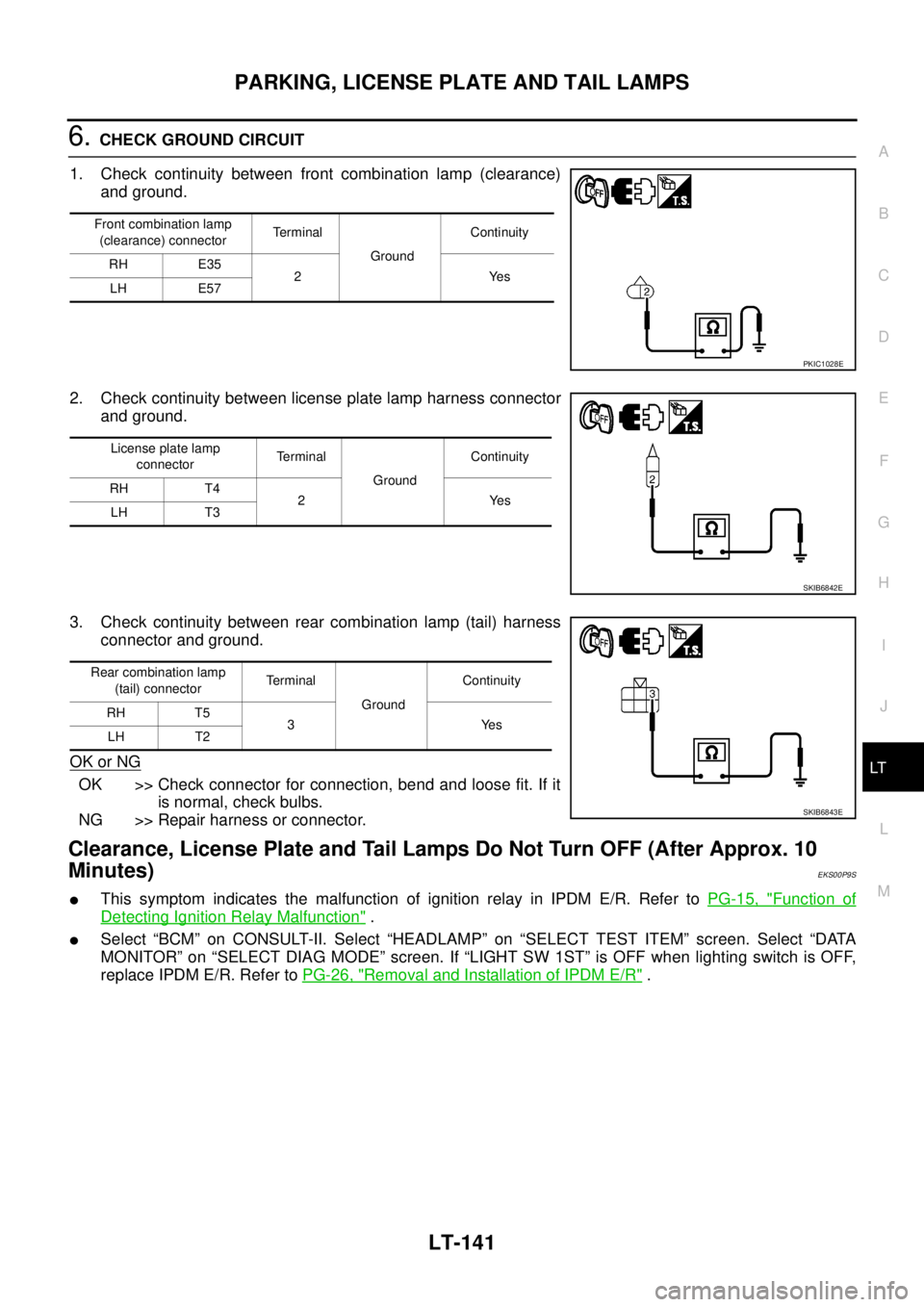
6.CHECK GROUND CIRCUIT
1. Check continuity between front combination lamp (clearance)
and ground.
2. Check continuity between license plate lamp harness connector
and ground.
3. Check continuity between rear combination lamp (tail) harness
connector and ground.
OK or NG
OK >> Check connector for connection, bend and loose fit. If it
is normal, check bulbs.
NG >> Repair harness or connector.
Clearance, License Plate and Tail Lamps Do Not Turn OFF (After Approx. 10
Minutes)
EKS00P9S
lThis symptom indicates the malfunction of ignition relay in IPDM E/R. Refer toPG-15, "Function of
Detecting Ignition Relay Malfunction".
lSelect “BCM” on CONSULT-II. Select “HEADLAMP” on “SELECT TEST ITEM” screen. Select “DATA
MONITOR” on “SELECT DIAG MODE” screen. If “LIGHT SW 1ST” is OFF when lighting switch is OFF,
replace IPDM E/R. Refer toPG-26, "
Removal and Installation of IPDM E/R".
Front combination lamp
(clearance) connectorTerminal
GroundContinuity
RH E35
2Yes
LH E57
PKIC1028E
License plate lamp
connectorTerminal
GroundContinuity
RH T4
2Yes
LH T3
SKIB6842E
Rear combination lamp
(tail) connectorTerminal
GroundContinuity
RH T5
3Yes
LH T2
SKIB6843E
Page 2245 of 3171

LT-162
ILLUMINATION
ILLUMINATION
PFP:27545
System DescriptionEKS00P8V
Control of the illumination lamps operation is dependent upon the position of the lighting switch (combination
switch). When the lighting switch is placed in the 1ST position, 2ND position or AUTO position (headlamp is
ON) the BCM (body control module) receives input signal requesting the illumination lamps to illuminate. This
input signal is communicated to the IPDM E/R (intelligent power distribution module engine room) through the
CAN communication. The CPU (central processing unit) of the IPDM E/R controls the tail lamp relay coil. This
relay, when energized, directs power to the illumination lamps, which then illuminate.
Power is supplied at all times
lto ignition relay (located in IPDM E/R) and
lto tail lamp relay (located in IPDM E/R), from battery directly,
lthrough 50A fusible link (letter G, located in fuse and fusible link box)
lto BCM terminal 57,
lthrough 20A fuse (No. 52, located in IPDM E/R) and
lthrough 20A fuse (No. 53, located in IPDM E/R)
lto CPU (located in IPDM E/R),
lthrough 10A fuse [No.19, located in fuse block (J/B)]
lto combination meter terminal 3.
With the ignition switch in the ON or START position, power is supplied
lto ignition relay (located in IPDM E/R),
lthrough 10A fuse [No. 1, located in fuse block (J/B)]
lto BCM terminal 3,
lthrough 10A fuse [No. 14, located in fuse block (J/B)]
lto combination meter 16.
Ground is supplied
lto BCM terminal 55 and
lto combination meter terminal 23
lthrough grounds M21, M80 and M83,
lto IPDM E/R terminals 38 and 59
lthrough grounds E21, E41 and E61.
ILLUMINATION OPERATION BY LIGHTING SWITCH
With the lighting switch in the 1ST position, 2ND position or AUTO position (headlamp is ON), the BCM
receives input signal requesting the illumination lamps to illuminate. This input signal is communicated to the
IPDM E/R through the CAN communication. The CPU of the IPDM E/R controls the tail lamp relay coil, which,
when energized, directs power
lthrough 10A fuse (No. 37, located in IPDM E/R)
lthrough IPDM E/R terminal 57
lto hazard switch (illumination) terminal 3
lto 4WD shift switch (illumination) terminal 7 (with 4-wheel drive)
lto front air control (illumination) terminal 8
lto audio unit (illumination) terminal 2 (1CD player)
lto audio unit (illumination) terminal 8 (6CD player)
lto AV switch (illumination) terminal 3 (with NAVI)
lto audio unit (illumination) terminal 29 (with NAVI)
lto glove box lamp terminal 1
lto A/T device (illumination) terminal 3 (with A/T)
lto heat up switch (illumination) terminal 5
lto DIFF LOCK switch (illumination) terminal 4 (with DIFF LOCK)
lto heated seat switch (driver side) (illumination) terminal 5 (with heated seats)
lto heated seat switch (passenger side) (illumination) terminal 5 (with heated seats)
Page 2246 of 3171
ILLUMINATION
LT-163
C
D
E
F
G
H
I
J
L
MA
B
LT
lto cigarette lighter (illumination) terminal 1
lto ashtray (illumination) terminal 1
lto headlamp washer switch (illumination) terminal 3
lto headlamp aiming switch (illumination) terminal 3 and
lto NAVI control unit (illumination) terminal 61 (with NAVI).
Ground is supplied
lto hazard switch (illumination) terminal 4
lto 4WD shift switch (illumination) terminal 8 (with 4-wheel drive)
lto front air control (illumination) terminal 9
lto AV switch (illumination) terminal 4 (with NAVI)
lto audio unit (illumination) terminal 28 (with NAVI)
lto DIFF LOCK switch (illumination) terminal 5 (with DIFF LOCK)
lto heated seat switch (driver side) (illumination) terminal 6 (with heated seats) and
lto heated seat switch (passenger side) (illumination) terminal 6 (with heated seats)
lthrough combination meter terminal 22
lthrough combination meter terminal 23
lthrough ground M21, M80 and M83,
lto glove box lamp terminal 2
lto A/T device (illumination) terminal 5 (with A/T)
lto heat up switch (illumination) terminal 6
lto ashtray (illumination) terminal 2
lto headlamp washer switch (illumination) terminal 4 and
lto headlamp aiming switch (illumination) terminal 4
ltrough ground M21, M80 and M83,
lto audio unit (illumination) (1CD and 6CD player)
lthrough case ground of audio unit,
lto cigarette lighter (illumination)
lthrough case ground of cigarette lighter,
lto NAVI control unit (illumination) terminal 1 (with NAVI)
lthrough ground B106 and B121.
With power and ground supplied, illumination lamps illuminate.
CAN Communication System DescriptionEKS00P8W
Refer toLAN-23, "CAN COMMUNICATION".
CAN Communication UnitEKS00P8X
Refer toLAN-30, "CAN Communication Unit".