Page 3158 of 3171

HEADLAMP WASHER
WW-47
C
D
E
F
G
H
I
J
L
MA
B
WW
ACTIVE TEST
Operation Procedure
1. Touch “WIPER” on “SELECT TEST ITEM” screen.
2. Touch “ACTIVE TEST” on “SELECT DIAG MODE” screen.
3. Touch item to be tested and check operation of the selected item.
4. During the operation check, touching “OFF” deactivates the operation.
Display Item List
RR WIPER INT “ON/OFF”Displays status (rear wiper switch intermittent position: ON/other: OFF) of rear wiper intermit-
tent switch judged from the wiper switch signal.
RR WIPER ON “ON/OFF”Displays status (rear wiper switch ON position: ON/other: OFF) of rear wiper switch judged from
the wiper switch signal.
RR WASHER SW “ON/OFF”Displays status (rear washer switch ON position: ON/other: OFF) of rear washer switch judged
from the wiper switch signal.
RR WIPER STOP “ON/OFF”Displays status (rear wiper move: ON/stop position: OFF) of rear wiper motor stop judged from
the rear wiper auto stop signal.
HL WASHER SW “ON/OFF”Displays status (headlamp washer switch ON position: ON/other: OFF) of headlamp washer
switch judged from headlamp washer switch signal.
HEAD LAMP SW 1 “ON/OFF”Displays status (lighting switch 2ND position: ON/other: OFF) of headlamp 1 switch judged from
thelightingswitchsignal.
HEAD LAMP SW 2 “ON/OFF”Displays status (lighting switch 2ND position: ON/other: OFF) of headlamp 2 switch judged from
thelightingswitchsignal. Monitor item Contents
Test item Display on CONSULT-II screen Description
Front wiper HI output FR WIPER (HI) Front wiper HI can be operated by any ON-OFF operation.
Front wiper LOW output FR WIPER (LOW) Front wiper LOW can be operated by any ON-OFF operation.
Front wiper INT output FR WIPER (INT) Front wiper INT can be operated by any ON-OFF operation.
Rear wiper output RR WIPER Rear wiper can be operated by any ON (1.5 second)-OFF operation.
Headlamp washer output HEAD LAMP WASHER Headlamp washer can be operated by any ON-OFF operation.
Page 3159 of 3171

WW-48
HEADLAMP WASHER
CONSULT-II Functions (IPDM E/R)
EKS00P6F
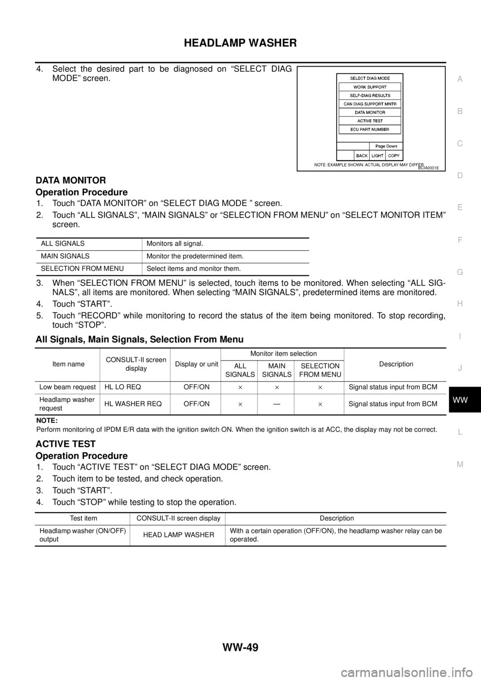
CONSULT-II can display each diagnostic item using the diagnostic test mode shown following.
CONSULT-II BASIC OPERATION
CAUTION:
If CONSULT-II is used with no connection of CONSULT-II CONVERTER, malfunctions might be
detected in self-diagnosis depending on control unit which carry out CAN communication.
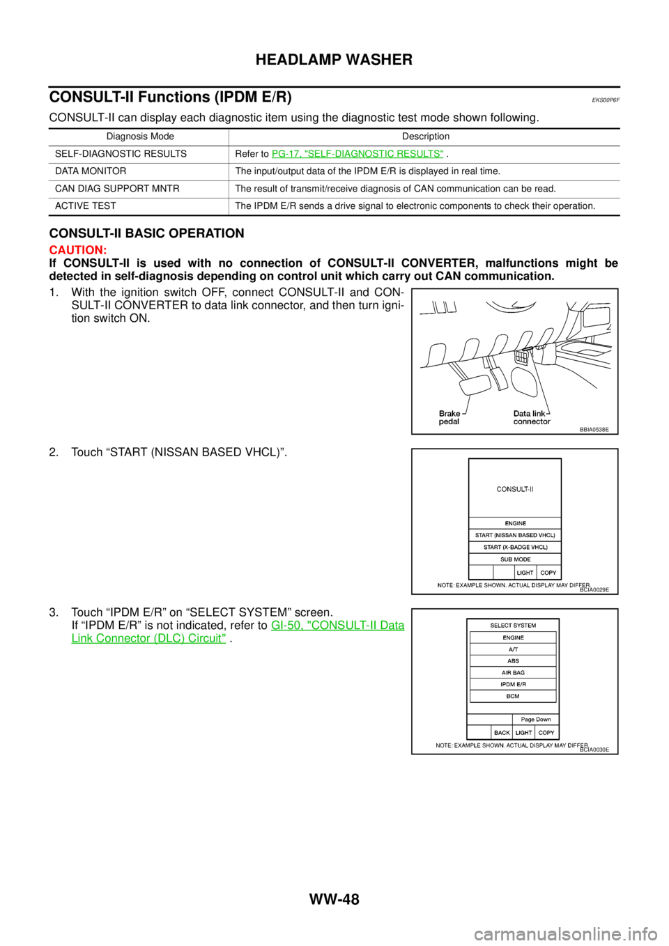
1. With the ignition switch OFF, connect CONSULT-II and CON-
SULT-II CONVERTER to data link connector, and then turn igni-
tion switch ON.
2. Touch “START (NISSAN BASED VHCL)”.
3. Touch “IPDM E/R” on “SELECT SYSTEM” screen.
If “IPDM E/R” is not indicated, refer toGI-50, "
CONSULT-II Data
Link Connector (DLC) Circuit".
Diagnosis Mode Description
SELF-DIAGNOSTIC RESULTS Refer toPG-17, "
SELF-DIAGNOSTIC RESULTS".
DATA MONITOR The input/output data of the IPDM E/R is displayed in real time.
CAN DIAG SUPPORT MNTR The result of transmit/receive diagnosis of CAN communication can be read.
ACTIVE TEST The IPDM E/R sends a drive signal to electronic components to check their operation.
BBIA0538E
BCIA0029E
BCIA0030E
Page 3160 of 3171

HEADLAMP WASHER
WW-49
C
D
E
F
G
H
I
J
L
MA
B
WW
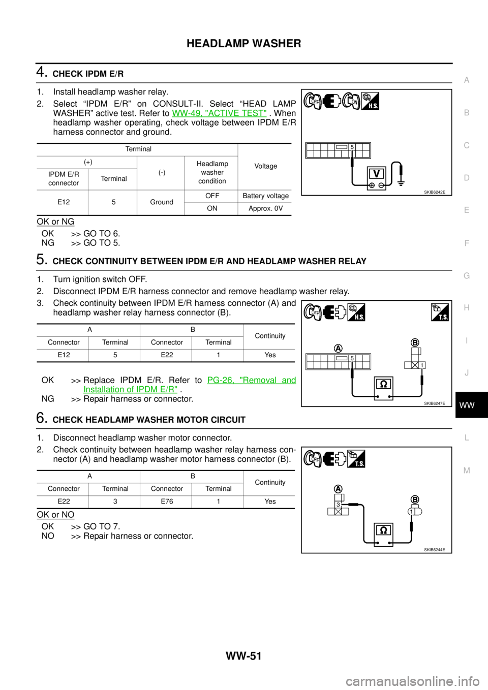
4. Select the desired part to be diagnosed on “SELECT DIAG
MODE” screen.
DATA MONITOR
Operation Procedure
1. Touch “DATA MONITOR” on “SELECT DIAG MODE ” screen.
2. Touch “ALL SIGNALS”, “MAIN SIGNALS” or “SELECTION FROM MENU” on “SELECT MONITOR ITEM”
screen.
3. When “SELECTION FROM MENU” is selected, touch items to be monitored. When selecting “ALL SIG-
NALS”, all items are monitored. When selecting “MAIN SIGNALS”, predetermined items are monitored.
4. Touch “START”.
5. Touch “RECORD” while monitoring to record the status of the item being monitored. To stop recording,
touch “STOP”.
All Signals, Main Signals, Selection From Menu
NOTE:
Perform monitoring of IPDM E/R data with the ignition switch ON. When the ignition switch is at ACC, the display may not be correct.
ACTIVE TEST
Operation Procedure
1. Touch “ACTIVE TEST” on “SELECT DIAG MODE” screen.
2. Touch item to be tested, and check operation.
3. Touch “START”.
4. Touch “STOP” while testing to stop the operation.
BCIA0031E
ALL SIGNALS Monitors all signal.
MAIN SIGNALS Monitor the predetermined item.
SELECTION FROM MENU Select items and monitor them.
Item nameCONSULT-II screen
displayDisplay or unitMonitor item selection
Description
ALL
SIGNALSMAIN
SIGNALSSELECTION
FROM MENU
Low beam request HL LO REQ OFF/ON´´ ´Signal status input from BCM
Headlamp washer
requestHL WASHER REQ OFF/ON´—´Signal status input from BCM
Test item CONSULT-II screen display Description
Headlamp washer (ON/OFF)
outputHEAD LAMP WASHERWith a certain operation (OFF/ON), the headlamp washer relay can be
operated.
Page 3161 of 3171
WW-50
HEADLAMP WASHER
Headlamp Washer Does Not Operate
EKS00P6G
1.ACTIVE TEST
1. Select “BCM” on CONSULT-II. Select “ACTIVE TEST” on
“SELECT DIAG MODE” screen.
2. Select “HEAD LAMP WASHER” on “SELECT TEST ITEM”
screen.
3. Touch “ON” screen.
Does headlamp washer operate normally?
YES >> GO TO 8.
NO >> GO TO 2.
2.CHECK POWER SUPPLY CIRCUIT TO HEADLAMP WASHER RELAY
1. Turn ignition switch OFF.
2. Remove headlamp washer relay.
3. Turn ignition switch ON.
4. Check voltage between headlamp washer relay harness con-
nector and ground.
OK or NG
OK >> GO TO 3.
NG >> Repair harness or connector.
3.CHECK HEADLAMP WASHER RELAY
1. Apply battery voltage to between headlamp washer relay termi-
nal 1 and 2.
2. Check continuity between terminal 3 and 5.
OK or NG
OK >> GO TO 4.
NG >> Replace headlamp washer relay.
SKIB6240E
Terminal
Voltage (+)
(-)
Headlamp washer
relay connectorTerminal
E222
Ground Battery voltage
5
SKIB6241E
3 – 5 : Continuity should exist.
SKIB6243E
Page 3162 of 3171

HEADLAMP WASHER
WW-51
C
D
E
F
G
H
I
J
L
MA
B
WW
4.CHECK IPDM E/R
1. Install headlamp washer relay.
2. Select “IPDM E/R” on CONSULT-II. Select “HEAD LAMP
WASHER” active test. Refer toWW-49, "
ACTIVE TEST".When
headlamp washer operating, check voltage between IPDM E/R
harness connector and ground.
OK or NG
OK >> GO TO 6.
NG >> GO TO 5.
5.CHECK CONTINUITY BETWEEN IPDM E/R AND HEADLAMP WASHER RELAY
1. Turn ignition switch OFF.
2. Disconnect IPDM E/R harness connector and remove headlamp washer relay.
3. Check continuity between IPDM E/R harness connector (A) and
headlamp washer relay harness connector (B).
OK >> Replace IPDM E/R. Refer toPG-26, "
Removal and
Installation of IPDM E/R".
NG >> Repair harness or connector.
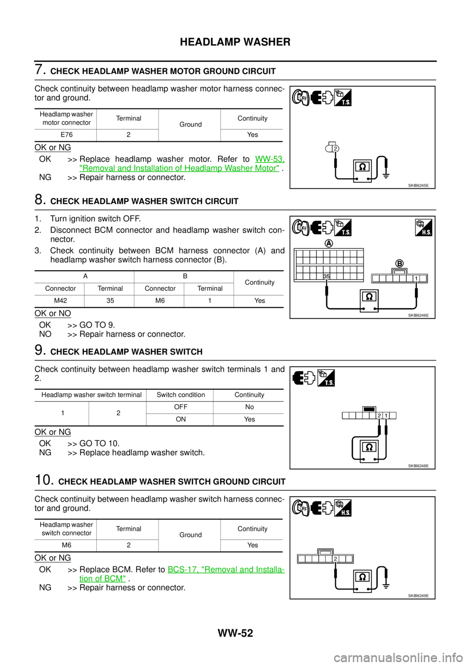
6.CHECK HEADLAMP WASHER MOTOR CIRCUIT
1. Disconnect headlamp washer motor connector.
2. Check continuity between headlamp washer relay harness con-
nector (A) and headlamp washer motor harness connector (B).
OK or NO
OK >> GO TO 7.
NO >> Repair harness or connector.
Terminal
Vo l ta g e (+)
(-)Headlamp
washer
condition IPDM E/R
connectorTerminal
E12 5 GroundOFF Battery voltage
ON Approx. 0V
SKIB6242E
AB
Continuity
Connector Terminal Connector Terminal
E12 5 E22 1 Yes
SKIB6247E
AB
Continuity
Connector Terminal Connector Terminal
E22 3 E76 1 Yes
SKIB6244E
Page 3163 of 3171

WW-52
HEADLAMP WASHER
7.CHECK HEADLAMP WASHER MOTOR GROUND CIRCUIT
Check continuity between headlamp washer motor harness connec-
tor and ground.
OK or NG
OK >> Replace headlamp washer motor. Refer toWW-53,
"Removal and Installation of Headlamp Washer Motor".
NG >> Repair harness or connector.
8.CHECK HEADLAMP WASHER SWITCH CIRCUIT
1. Turn ignition switch OFF.
2. Disconnect BCM connector and headlamp washer switch con-
nector.
3. Check continuity between BCM harness connector (A) and
headlamp washer switch harness connector (B).
OK or NO
OK >> GO TO 9.
NO >> Repair harness or connector.
9.CHECK HEADLAMP WASHER SWITCH
Check continuity between headlamp washer switch terminals 1 and
2.
OK or NG
OK >> GO TO 10.
NG >> Replace headlamp washer switch.
10.CHECK HEADLAMP WASHER SWITCH GROUND CIRCUIT
Check continuity between headlamp washer switch harness connec-
tor and ground.
OK or NG
OK >> Replace BCM. Refer toBCS-17, "Removal and Installa-
tion of BCM".
NG >> Repair harness or connector.
Headlamp washer
motor connectorTerminal
GroundContinuity
E76 2 Yes
SKIB6245E
AB
Continuity
Connector Terminal Connector Terminal
M42 35 M6 1 Yes
SKIB6246E
Headlamp washer switch terminal Switch condition Continuity
12OFF No
ON Yes
SKIB6248E
Headlamp washer
switch connectorTerminal
GroundContinuity
M6 2 Yes
SKIB6249E
Page 3164 of 3171
HEADLAMP WASHER
WW-53
C
D
E
F
G
H
I
J
L
MA
B
WW
Removal and Installation of Washer NozzleEKS00P6H
REMOVAL
1. Remove front bumper fascia. Refer toEI-15, "FRONT
BUMPER".
2. Remove headlamp washer tube (B).
3. Remove headlamp washer nozzle clip (A).
4. Remove headlamp washer nozzle (C) from front bumper.
INSTALLATION
Installation is the reverse order of removal.
Removal and Installation of Washer TankEKS00P6I
Refer toWW-37, "Removal and Installation of Front Washer Tank".
Removal and Installation of Headlamp Washer MotorEKS00P6J
REMOVAL
: Vehicle front
1. Remove front washer tank. Refer toWW-37, "
Removal and Installation of Front Washer Tank".
2. Remove headlamp washer motor (1) from front washer tank.
INSTALLATION
Installation is the reverse order of removal.
CAUTION:
When installing headlamp washer motor, there should be no packing twist, etc.
PKIC0463E
SKIB6858E
Page 3165 of 3171
WW-54
HEADLAMP WASHER
Washer Tube Layout
EKS00P6K
PKIC0464E