2005 NISSAN NAVARA headlamp
[x] Cancel search: headlampPage 2256 of 3171

BULB SPECIFICATIONS
LT-173
C
D
E
F
G
H
I
J
L
MA
B
LT
BULB SPECIFICATIONSPFP:26297
HeadlampEKS00P82
Exterior LampEKS00P83
Interior Lamp/IlluminationEKS00P84
Item Wattage (W)
High/Low60/55 (H4LL)
Item Wattage (W)
Front combination lampTurn signal lamp 21
Clearance lamp 5
Rear combination lampStop/Tail lamp 21/5
Turn signal lamp 21
Back- up lamp 16
Rear fog lamp 21
Side turn signal lamp5
Front fog lamp55
License plate lamp5
Item Wattage (W)
Glove box lamp3.4
Room/Map lamp6
A/T device lamp3
Page 2282 of 3171
GENERAL MAINTENANCE
MA-7
C
D
E
F
G
H
I
J
K
MA
B
MA
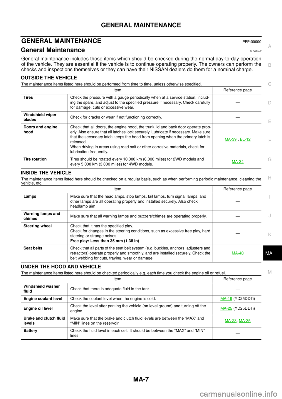
GENERAL MAINTENANCEPFP:00000
General MaintenanceELS001HT
General maintenance includes those items which should be checked during the normal day-to-day operation
of the vehicle. They are essential if the vehicle is to continue operating properly. The owners can perform the
checks and inspections themselves or they can have their NISSAN dealers do them for a nominal charge.
OUTSIDE THE VEHICLE
The maintenance items listed here should be performed from time to time, unless otherwise specified.
INSIDE THE VEHICLE
The maintenance items listed here should be checked on a regular basis, such as when performing periodic maintenance, cleaning the
vehicle, etc.
UNDER THE HOOD AND VEHICLE
The maintenance items listed here should be checked periodically e.g. each time you check the engine oil or refuel.Item Reference page
TiresCheck the pressure with a gauge periodically when at a service station, includ-
ing the spare, and adjust to the specified pressure if necessary. Check carefully
for damage, cuts or excessive wear.—
Windshield wiper
bladesCheck for cracks or wear if not functioning correctly. —
Doors and engine
hoodCheck that all doors, the engine hood, the trunk lid and back door operate prop-
erly. Also ensure that all latches lock securely. Lubricate if necessary. Make sure
that the secondary latch keeps the hood from opening when the primary latch is
released.
When driving in areas using road salt or other corrosive materials, check for
lubrication frequently.MA-39
,BL-12
Tire rotationTires should be rotated every 10,000 km (6,000 miles) for 2WD models and
every 5,000 km (3,000 miles) for 4WD models.MA-34
Item Reference page
LampsMake sure that the headlamps, stop lamps, tail lamps, turn signal lamps, and
other lamps are all operating properly and installed securely. Also check
headlamp aim.—
Warning lamps and
chimesMake sure that all warning lamps and buzzers/chimes are operating properly. —
Steering wheelCheck that it has the specified play.
Check for changes in the steering conditions, such as excessive free play, hard
steering or strange noises.
Free play: Less than 35 mm (1.38 in)—
Seat beltsCheck that all parts of the seat belt system (e.g. buckles, anchors, adjusters and
retractors) operate properly and smoothly, and are installed securely. Check the
belt webbing for cuts, fraying, wear or damage.MA-40
Item Reference page
Windshield washer
fluidCheck that there is adequate fluid in the tank. —
Engine coolant levelCheck the coolant level when the engine is cold.MA-19
(YD25DDTi)
Engine oil levelCheck the level after parking the vehicle (on level ground) and turning off the
engine.MA-25
(YD25DDTi)
Brake and clutch fluid
levelsMake sure that the brake and clutch fluid levels are between the “MAX” and
“MIN” lines on the reservoir.MA-28
,MA-35
BatteryCheck the fluid level in each cell. It should be between the “MAX” and “MIN”
lines.—
Page 2284 of 3171
PERIODIC MAINTENANCE
MA-9
C
D
E
F
G
H
I
J
K
MA
B
MA
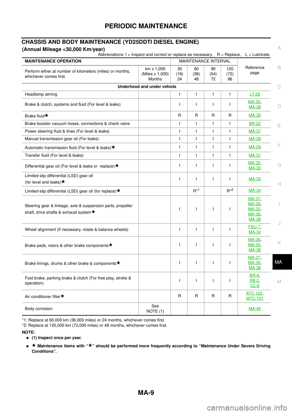
CHASSIS AND BODY MAINTENANCE (YD25DDTI DIESEL ENGINE)
(Annual Mileage <30,000 Km/year)
Abbreviations: I = Inspect and correct or replace as necessary, R = Replace, L = Lubricate.
*1: Replace at 60,000 km (36,000 miles) or 24 months, whichever comes first.
*2: Replace at 120,000 km (72,000 miles) or 48 months, whichever comes first.
NOTE:
l(1) Inspect once per year.
lMaintenance items with “ ” should be performed more frequently according to “Maintenance Under Severe Driving
Conditions”. MAINTENANCE OPERATIONMAINTENANCE INTERVAL
Reference
page Perform either at number of kilometers (miles) or months,
whichever comes first.km x 1,000
(Miles x 1,000)
Months30
(18)
2460
(36)
4890
(54)
72120
(72)
96
Underhood and under vehicle
Headlampaiming IIIILT- 2 8
Brake&clutch,systemsandfluid(Forlevel&leaks) IIIIMA-35,
MA-28
Brake fluidRRRRMA-35
Brakeboostervacuumhoses,connections&checkvalve IIIIBR-22
Powersteeringfluid&lines(Forlevel&leaks) IIIIMA-37
Manual transmission gear oil (For leaks)IIIIMA-28
Automatic transmission fluid (For level & leaks)IIIIMA-29
Transferfluid(Forlevel&leaks) IIIIMA-31
Differential gear oil (For level & leaks or replace)IIIIMA-32,
MA-33
Limited-slip differential (LSD) gear oil
(for level and leaks)IIIIMA-33
Limited-slip differential (LSD) gear oil (for replace)R*1R*2MA-34
Steering gear & linkage, axle & suspension parts, propeller
shaft, drive shafts & exhaust systemIIIIMA-37
,
MA-38
,
MA-32
,
MA-38
,
MA-28
Wheelalignment(Ifnecessary,rotate&balancewheels) IIIIFSU-7,
MA-34
Brake pads, rotors & other brake componentsIIIIMA-36
,
MA-35
,
MA-36
Brake linings, drums & other brake & componentsIIIIMA-37
,
MA-36
,
MA-36
Foot brake, parking brake & clutch (For free play, stroke &
operation)IIIIBR-6,
PB-2
,
CL-6
Air conditioner filterRRRRATC-122,
MTC-101
Body corrosionSee
NOTE (1)MA-40
Page 2286 of 3171
PERIODIC MAINTENANCE
MA-11
C
D
E
F
G
H
I
J
K
MA
B
MA
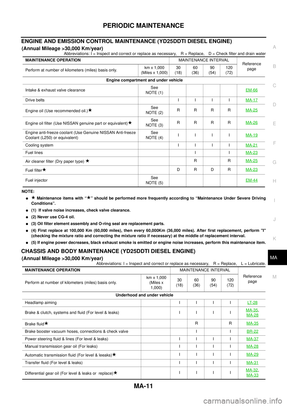
ENGINE AND EMISSION CONTROL MAINTENANCE (YD25DDTI DIESEL ENGINE)
(Annual Mileage >30,000 Km/year)
Abbreviations: I = Inspect and correct or replace as necessary, R = Replace, D = Check filter and drain water
NOTE:
lMaintenance items with “ ” should be performed more frequently according to “Maintenance Under Severe Driving
Conditions”.
l(1) If valve noise increases, check valve clearance.
l(2)NeveruseCG-4oil.
l(3) Oil filter element assembly and O-ring seal are replacement parts.
l(4) First replace at 100,000 Km (60,000 miles), then every 60,000Km (36,000 miles). After first replacement, perform "I"
(checking the mixture ratio and correcting the mixture ratio if necessary) at the middle of replacement interval.
l(5) If engine power decreases, black exhaust smoke is emitted or engine noise increases, perform this maintenance item.
CHASSIS AND BODY MAINTENANCE (YD25DDTI DIESEL ENGINE)
(Annual Mileage >30,000 Km/year)
Abbreviations: I = Inspect and correct or replace as necessary, R = Replace, L = Lubricate. MAINTENANCE OPERATIONMAINTENANCE INTERVAL
Reference
page
Perform at number of kilometers (miles) basis only.km x 1,000
(Miles x 1,000)30
(18)60
(36)90
(54)120
(72)
Engine compartment and under vehicle
Intake & exhaust valve clearanceSee
NOTE (1)EM-66
Drive beltsIIIIMA-17
Engine oil (Use recommended oil.)See
NOTE (2)RRRRMA-25
Engine oil filter (Use NISSAN genuine part or equivalent)See
NOTE (3)RRRRMA-26
Engine anti-freeze coolant (Use Genuine NISSAN Anti-freeze
Coolant (L250) or equivalent)See
NOTE (4)IIIIMA-19
Cooling system I I I IMA-21
Fuel linesIIMA-23
Air cleaner filter (Dry paper type)RRMA-25
Fuel filterDRDRMA-23
Fuel injectorSee
NOTE (5)EM-44
MAINTENANCE OPERATIONMAINTENANCE INTERVAL
Reference
page
Perform at number of kilometers (miles) basis only.km x 1,000
(Miles x
1,000)30
(18)60
(36)90
(54)120
(72)
Underhood and under vehicle
Headlamp aiming I I I ILT- 2 8
Brake & clutch, systems and fluid (For level & leaks) I I I IMA-35,
MA-28
Brake fluidRRMA-35
Brake booster vacuum hoses, connections & check valve I IBR-22
Power steering fluid & lines (For level & leaks) I I I IMA-37
Manual transmission gear oil (For leaks) I I I IMA-28
Automatic transmission fluid (For level & leeaks)IIIIMA-29
Transfer fluid (For level & leaks) I I I IMA-31
Differential gear oil (For level & leaks or replace)IIIIMA-32,
MA-33
Page 2543 of 3171

PG-14
IPDM E/R (INTELLIGENT POWER DISTRIBUTION MODULE ENGINE ROOM)
IPDM E/R (INTELLIGENT POWER DISTRIBUTION MODULE ENGINE ROOM)
PFP:284B7
System DescriptionEKS00PA8
lIPDM E/R (Intelligent Power Distribution Module Engine Room) integrates the relay box and fuse block
which were originally placed in engine compartment. It controls integrated relays via IPDM E/R control cir-
cuits.
lIPDM E/R-integrated control circuits perform ON-OFF operation of relays, CAN communication control,
etc.
lIt controls operation of each electrical component via ECM, BCM and CAN communication lines.
CAUTION:
None of the IPDM E/R integrated relays can be removed.
SYSTEMS CONTROLLED BY IPDM E/R
IPDM E/R receives a request signal from each Control unit with CAN communication. It controls each system.
CAN COMMUNICATION LINE CONTROL
With CAN communication, by connecting each control unit using two communication lines (CAN L-line, CAN
H-line), it is possible to transmit a maximum amount of information with minimum wiring. Each control unit can
transmit and receive data, and reads necessary information only.
1. Fail-safe control
lWhen CAN communication with other control units is impossible, IPDM E/R performs fail-safe control.
After CAN communication returns to normal operation, it also returns to normal control.
lOperation of control parts by IPDM E/R during fail-safe mode is as follows:
Control system Transmit control unit Control part
Lamp control BCM
lHead lamps (HI, LO)
lTail lamps, parking and license plate lamps
lFront fog lamps
Wiper control BCM Front wipers
Rear window defogger control BCM Rear window defogger
A/C compressor control ECM A/C compressor
Starter control TCM Starter motor
Cooling fan control ECM Cooling fan
Controlled system Fail-safe mode
Headlamps
lWith the ignition switch ON, the headlamp low is ON.
lWith the ignition switch OFF, the headlamp low is OFF.
Tail, parking and license plate lamps
lWith the ignition switch ON, the tail lamp is ON.
lWith the ignition switch OFF, the tail lamp is OFF.
Cooling fan
lWith the ignition switch ON, the cooling fan HI operates.
lWith the ignition switch OFF, the cooling fan stops.
Front wipersUntil the ignition switch is turned off, the front wiper LO and HI remains in the same status it
was in just before fail-safe control was initiated.
Rear window defogger Rear window defogger OFF
A/C compressor A/C compressor OFF
Front fog lamps Front fog lamp OFF
Page 2547 of 3171

PG-18
IPDM E/R (INTELLIGENT POWER DISTRIBUTION MODULE ENGINE ROOM)
5. Touch “RECORD” while monitoring to record the status of the item being monitored. To stop recording,
touch “STOP”.
All Signals, Main Signals, Selection From Menu
NOTE:
Perform monitoring of IPDM E/R data with the ignition switch ON. When the ignition switch is in ACC position,
display may not be correct.
CAN DIAG SUPPORT MNTR
Refer toLAN-15, "CAN Diagnostic Support Monitor".
ACTIVE TEST
Operation Procedure
1. Touch “ACTIVE TEST” on “SELECT DIAG-MODE” screen.
2. Touch item to be tested, and check operation.
3. Touch “START”.
4. Touch “STOP” while testing to stop the operation.
Item nameCONSULT-II
screen displayDisplay or unitMonitor item selection
Description
ALL
SIGNALSMAIN
SIGNALSSELECTION
FROM MENU
Motor fan requestMOTOR FAN
REQ1/2/3/4 X X X Signal status input from ECM
A/C compressor
requestAC COMP REQ ON/OFF X X X Signal status input from ECM
Tail & clear
requestTAIL & CLR REQ ON/OFF X X X Signal status input from BCM
Headlamp LO
requestHL LO REQ ON/OFF X X X Signal status input from BCM
Headlamp HI
requestHL HI REQ ON/OFF X X X Signal status input from BCM
Front fog lamp
requestFR FOG REQ ON/OFF X X X Signal status input from BCM
Headlamp washer
requestHL WASHER
REQON/OFF X X Signal from input from BCM
Front wiper
requestFR WIP REQSTOP/1LOW/
LOW/HIX X X Signal status input from BCM
Wiper auto stopWIP AUTO
STOPACT P/STOP P X X X Output status of IPDM E/R
Wiper protection WIP PROT OFF/BLOCK X X X Control status of IPDM E/R
Starter request ST RLY REQ ON/OFF X X
Status of input signal
NOTE
Ignition relay
statusIGN RLY ON/OFF X X XIgnition relay status monitored
with IPDM E/R
Rear defogger
requestRR DEF REQ ON/OFF X X X Signal status input from BCM
Oil pressure
switchOIL P SW OPEN/CLOSE X XSignal status input from IPDM
E/R
Hood switch HOOD SW OFF XSignal status input from IPDM
E/R (function is not enabled)
Theft warning
horn requestTHFT HRN REQ ON/OFF X X Signal status input from BCM
Horn chirp HORN CHIRP ON/OFF X X Output status of IPDM E/R
Page 2548 of 3171
IPDM E/R (INTELLIGENT POWER DISTRIBUTION MODULE ENGINE ROOM)
PG-19
C
D
E
F
G
H
I
J
L
MA
B
PG
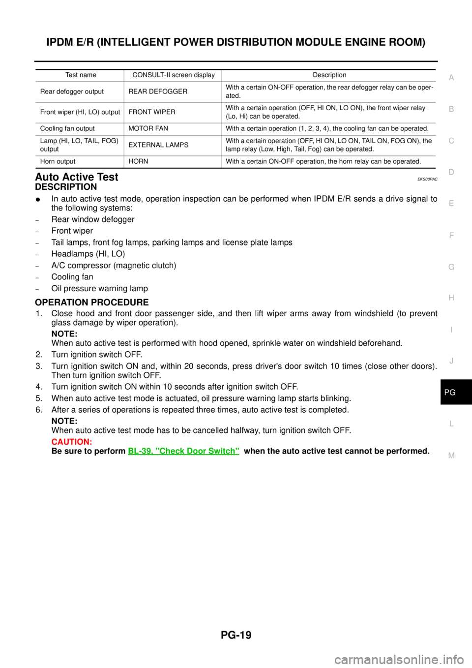
Auto Active TestEKS00PAC
DESCRIPTION
lIn auto active test mode, operation inspection can be performed when IPDM E/R sends a drive signal to
the following systems:
–Rear window defogger
–Front wiper
–Tail lamps, front fog lamps, parking lamps and license plate lamps
–Headlamps (HI, LO)
–A/C compressor (magnetic clutch)
–Cooling fan
–Oil pressure warning lamp
OPERATION PROCEDURE
1. Close hood and front door passenger side, and then lift wiper arms away from windshield (to prevent
glass damage by wiper operation).
NOTE:
When auto active test is performed with hood opened, sprinkle water on windshield beforehand.
2. Turn ignition switch OFF.
3. Turn ignition switch ON and, within 20 seconds, press driver's door switch 10 times (close other doors).
Then turn ignition switch OFF.
4. Turn ignition switch ON within 10 seconds after ignition switch OFF.
5. When auto active test mode is actuated, oil pressure warning lamp starts blinking.
6. After a series of operations is repeated three times, auto active test is completed.
NOTE:
When auto active test mode has to be cancelled halfway, turn ignition switch OFF.
CAUTION:
Be sure to performBL-39, "
Check Door Switch"when the auto active test cannot be performed.
Test name CONSULT-II screen display Description
Rear defogger output REAR DEFOGGERWith a certain ON-OFF operation, the rear defogger relay can be oper-
ated.
Front wiper (HI, LO) output FRONT WIPERWith a certain operation (OFF, HI ON, LO ON), the front wiper relay
(Lo, Hi) can be operated.
Cooling fan output MOTOR FAN With a certain operation (1, 2, 3, 4), the cooling fan can be operated.
Lamp (HI, LO, TAIL, FOG)
outputEXTERNAL LAMPSWith a certain operation (OFF, HI ON, LO ON, TAIL ON, FOG ON), the
lamp relay (Low, High, Tail, Fog) can be operated.
Horn output HORN With a certain ON-OFF operation, the horn relay can be operated.
Page 2549 of 3171
PG-20
IPDM E/R (INTELLIGENT POWER DISTRIBUTION MODULE ENGINE ROOM)
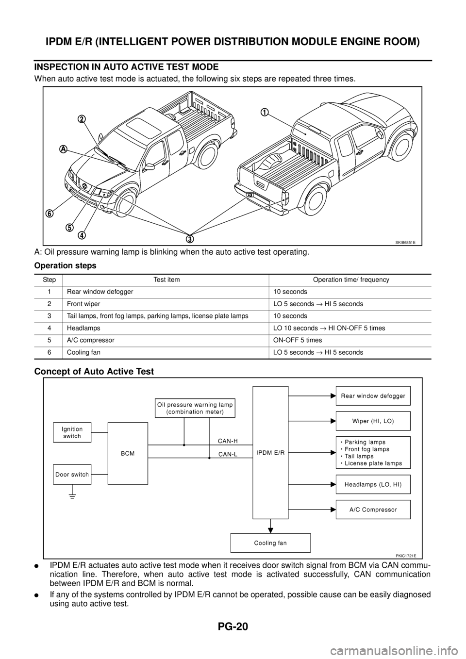
INSPECTION IN AUTO ACTIVE TEST MODE
When auto active test mode is actuated, the following six steps are repeated three times.
A: Oil pressure warning lamp is blinking when the auto active test operating.
Operation steps
Concept of Auto Active Test
lIPDM E/R actuates auto active test mode when it receives door switch signal from BCM via CAN commu-
nication line. Therefore, when auto active test mode is activated successfully, CAN communication
between IPDM E/R and BCM is normal.
lIf any of the systems controlled by IPDM E/R cannot be operated, possible cause can be easily diagnosed
using auto active test.
SKIB6851E
Step Test item Operation time/ frequency
1 Rear window defogger 10 seconds
2 Front wiper LO 5 seconds®HI 5 seconds
3 Tail lamps, front fog lamps, parking lamps, license plate lamps 10 seconds
4 Headlamps LO 10 seconds®HI ON-OFF 5 times
5 A/C compressor ON-OFF 5 times
6 Cooling fan LO 5 seconds®HI 5 seconds
PKIC1721E