2005 NISSAN NAVARA air filter
[x] Cancel search: air filterPage 337 of 3171
ATC-3
C
D
E
F
G
H
I
K
L
MA
B
AT C BLOWER MOTOR .................................................. 121
Components ......................................................... 121
Removal and Installation ...................................... 121
REMOVAL ......................................................... 121
INSTALLATION ................................................. 121
AIR CONDITIONER FILTER ................................... 122
Removal and Installation ...................................... 122
FUNCTION ........................................................ 122
REPLACEMENT TIMING .................................. 122
REPLACEMENT PROCEDURE ....................... 122
HEATER & COOLING UNIT ASSEMBLY .............. 124
Components ......................................................... 124
Removal and Installation ...................................... 126
REMOVAL ......................................................... 126
INSTALLATION ................................................. 126
HEATER CORE ...................................................... 127
Components ......................................................... 127
Removal and Installation ...................................... 127
REMOVAL ......................................................... 127
INSTALLATION ................................................. 127
HEATER PUMP ...................................................... 128
Components ......................................................... 128
Removal and Installation ...................................... 128
REMOVAL ......................................................... 128
INSTALLATION ................................................. 128
INTAKE DOOR MOTOR ......................................... 129
Components ......................................................... 129
Removal and Installation ...................................... 129
REMOVAL ......................................................... 129
INSTALLATION ................................................. 129
MODE DOOR MOTOR ........................................... 130
Components ......................................................... 130
Removal and Installation ...................................... 130
REMOVAL ......................................................... 130
INSTALLATION ................................................. 130
AIR MIX DOOR MOTOR ......................................... 131
Components ......................................................... 131
Removal and Installation ...................................... 131
AIR MIX DOOR MOTOR (DRIVER) .................. 131
AIR MIX DOOR MOTOR (PASSENGER) ......... 131
VARIABLE BLOWER CONTROL .......................... 133
Components ......................................................... 133
Removal and Installation ...................................... 133
REMOVAL ......................................................... 133
INSTALLATION ................................................. 133
DUCTS AND GRILLES .......................................... 134
Components ......................................................... 134
Removal and Installation ...................................... 136
CONSOLE DUCTS AND CONSOLE GRILLE .. 136
DEFROSTER NOZZLE ..................................... 136
RH AND LH SIDE DEMISTER DUCT ............... 136
RH AND LH VENTILATOR DUCT ..................... 136
CENTER VENTILATOR DUCT ......................... 136
FLOOR CONNECTOR DUCT ........................... 136
FRONT AND REAR FLOOR DUCTS ............... 137
REAR OVERHEAD DUCTS .............................. 137
SIDE REAR FLOOR DUCT .............................. 137
GRILLES ........................................................... 137REFRIGERANT LINES ...........................................138
HFC-134a (R-134a) Service Procedure ...............138
SETTING OF SERVICE TOOLS AND EQUIP-
MENT ................................................................138
Components .........................................................140
Removal and Installation for Compressor ............142
REMOVAL .........................................................142
INSTALLATION .................................................142
Removal and Installation for Compressor Clutch . 143
REMOVAL .........................................................143
INSPECTION ....................................................144
INSTALLATION .................................................144
BREAK-IN OPERATION ....................................146
Removal and Installation for High-pressure Flexible
A/C Hose ..............................................................146
REMOVAL .........................................................146
INSTALLATION .................................................146
Removal and Installation for High-pressure A/C
Pipe ......................................................................146
REMOVAL .........................................................146
INSTALLATION .................................................146
Removal and Installation for Low-pressure Flexible
A/C Hose ..............................................................146
REMOVAL .........................................................146
INSTALLATION .................................................146
Removal and Installation for Low-pressure A/C Pipe.147
REMOVAL .........................................................147
INSTALLATION .................................................147
Removal and Installation for Refrigerant Pressure
Sensor ..................................................................147
REMOVAL .........................................................147
INSTALLATION .................................................147
Removal and Installation for Condenser ..............147
REMOVAL .........................................................147
INSTALLATION .................................................148
Removal and Installation for Evaporator ..............149
REMOVAL .........................................................149
INSTALLATION .................................................149
Removal and Installation for Expansion Valve ......150
REMOVAL .........................................................150
INSTALLATION .................................................150
Checking for Refrigerant Leaks ............................150
Checking System for Leaks Using the Fluorescent
Leak Detector .......................................................150
Dye Injection .........................................................151
Electronic Refrigerant Leak Detector ....................151
PRECAUTIONS FOR HANDLING LEAK
DETECTOR .......................................................151
CHECKING PROCEDURE ...............................152
SERVICE DATA AND SPECIFICATIONS (SDS) ....154
Service Data and Specifications (SDS) ................154
COMPRESSOR ................................................154
LUBRICANT ......................................................154
REFRIGERANT .................................................154
ENGINE IDLING SPEED ..................................154
BELT TENSION .................................................154
Page 456 of 3171
ATC-122
AIR CONDITIONER FILTER
AIR CONDITIONER FILTER
PFP:27277
Removal and InstallationEJS006C7
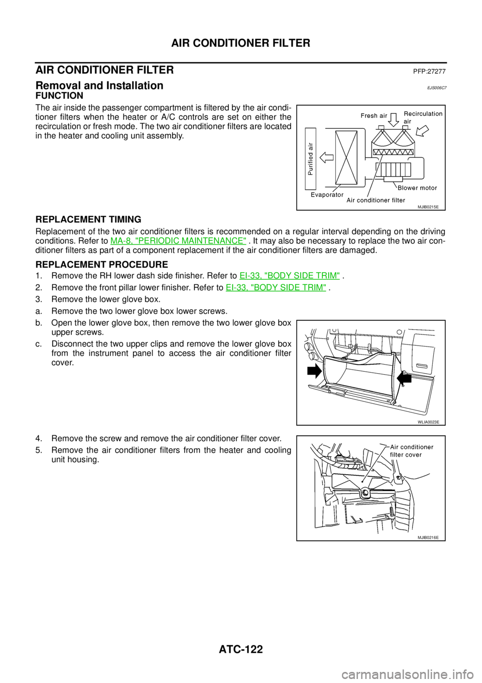
FUNCTION
The air inside the passenger compartment is filtered by the air condi-
tioner filters when the heater or A/C controls are set on either the
recirculation or fresh mode. The two air conditioner filters are located
in the heater and cooling unit assembly.
REPLACEMENT TIMING
Replacement of the two air conditioner filters is recommended on a regular interval depending on the driving
conditions. Refer toMA-8, "
PERIODIC MAINTENANCE". It may also be necessary to replace the two air con-
ditioner filters as part of a component replacement if the air conditioner filters are damaged.
REPLACEMENT PROCEDURE
1. Remove the RH lower dash side finisher. Refer toEI-33, "BODY SIDE TRIM".
2. Remove the front pillar lower finisher. Refer toEI-33, "
BODY SIDE TRIM".
3. Remove the lower glove box.
a. Remove the two lower glove box lower screws.
b. Open the lower glove box, then remove the two lower glove box
upper screws.
c. Disconnect the two upper clips and remove the lower glove box
from the instrument panel to access the air conditioner filter
cover.
4. Remove the screw and remove the air conditioner filter cover.
5. Remove the air conditioner filters from the heater and cooling
unit housing.
MJIB0215E
WLIA0023E
MJIB0216E
Page 457 of 3171
AIR CONDITIONER FILTER
ATC-123
C
D
E
F
G
H
I
K
L
MA
B
AT C
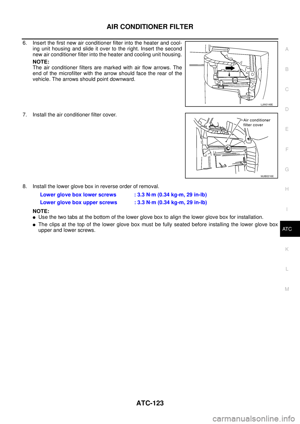
6. Insert the first new air conditioner filter into the heater and cool-
ing unit housing and slide it over to the right. Insert the second
new air conditioner filter into the heater and cooling unit housing.
NOTE:
The air conditioner filters are marked with air flow arrows. The
end of the microfilter with the arrow should face the rear of the
vehicle. The arrows should point downward.
7. Install the air conditioner filter cover.
8. Install the lower glove box in reverse order of removal.
NOTE:
lUse the two tabs at the bottom of the lower glove box to align the lower glove box for installation.
lThe clips at the top of the lower glove box must be fully seated before installing the lower glove box
upper and lower screws.
LJIA0148E
MJIB0216E
Lower glove box lower screws : 3.3 N·m (0.34 kg-m, 29 in-lb)
Lower glove box upper screws : 3.3 N·m (0.34 kg-m, 29 in-lb)
Page 461 of 3171
HEATER CORE
ATC-127
C
D
E
F
G
H
I
K
L
MA
B
AT C
HEATER COREPFP:27140
ComponentsEJS006CA
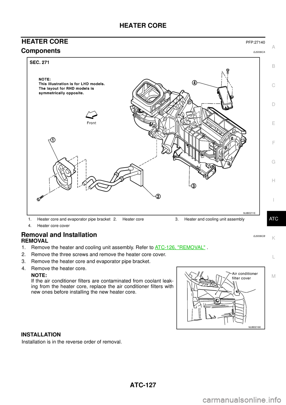
Removal and InstallationEJS006CB
REMOVAL
1. Remove the heater and cooling unit assembly. Refer toATC-126, "REMOVAL".
2. Remove the three screws and remove the heater core cover.
3. Remove the heater core and evaporator pipe bracket.
4. Remove the heater core.
NOTE:
If the air conditioner filters are contaminated from coolant leak-
ing from the heater core, replace the air conditioner filters with
new ones before installing the new heater core.
INSTALLATION
Installation is in the reverse order of removal.
1. Heater core and evaporator pipe bracket 2. Heater core 3. Heater and cooling unit assembly
4. Heater core cover
MJIB0211E
MJIB0216E
Page 892 of 3171
CO-8
ENGINE COOLANT
DRAINING ENGINE COOLANT
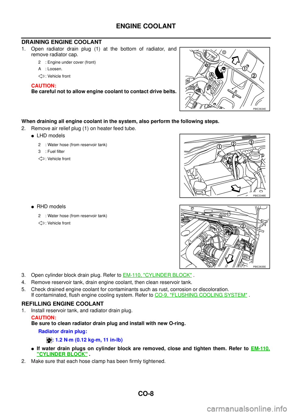
1. Open radiator drain plug (1) at the bottom of radiator, and
remove radiator cap.
CAUTION:
Be careful not to allow engine coolant to contact drive belts.
When draining all engine coolant in the system, also perform the following steps.
2. Remove air relief plug (1) on heater feed tube.
lLHD models
lRHD models
3. Open cylinder block drain plug. Refer toEM-110, "
CYLINDER BLOCK".
4. Remove reservoir tank, drain engine coolant, then clean reservoir tank.
5. Check drained engine coolant for contaminants such as rust, corrosion or discoloration.
If contaminated, flush engine cooling system. Refer toCO-9, "
FLUSHING COOLING SYSTEM".
REFILLING ENGINE COOLANT
1. Install reservoir tank, and radiator drain plug.
CAUTION:
Be sure to clean radiator drain plug and install with new O-ring.
lIf water drain plugs on cylinder block are removed, close and tighten them. Refer toEM-110,
"CYLINDER BLOCK".
2. Make sure that each hose clamp has been firmly tightened.
2 : Engine under cover (front)
A : Loosen.
: Vehicle front
PBIC3634E
2 : Water hose (from reservoir tank)
3 : Fuel filter
: Vehicle front
PBIC3348E
2 : Water hose (from reservoir tank)
: Vehicle front
PBIC3635E
Radiator drain plug:
: 1.2 N·m (0.12 kg-m, 11 in-lb)
Page 981 of 3171
EC-1
ENGINE CONTROL SYSTEM
B ENGINE
CONTENTS
C
D
E
F
G
H
I
J
K
L
M
SECTIONEC
A
EC
ENGINE CONTROL SYSTEM
INDEX FOR DTC ........................................................ 6
DTC No. Index ......................................................... 6
Alphabetical Index .................................................... 8
PRECAUTIONS ........................................................ 10
Precautions for Supplemental Restraint System
(SRS)“AIRBAG”and“SEATBELTPRE-TEN-
SIONER” ................................................................ 10
On Board Diagnostic (OBD) System of Engine ...... 10
Precautions ............................................................ 10
Wiring Diagrams and Trouble Diagnosis ................ 13
PREPARATION ......................................................... 14
Special Service Tools ............................................. 14
Commercial Service Tools ...................................... 14
ENGINE CONTROL SYSTEM .................................. 15
System Diagram ..................................................... 15
Vacuum Hose Drawing ........................................... 16
System Chart ......................................................... 18
Fuel Injection Control System ................................ 18
Fuel Injection Timing Control System ..................... 20
Air Conditioning Cut Control ................................... 20
Fuel Cut Control (At No Load & High Engine Speed)... 20
Crankcase Ventilation System ............................... 21
CAN Communication .............................................. 22
BASIC SERVICE PROCEDURE .............................. 23
Fuel Filter ............................................................... 23
Fuel Pump Learning Value Clearing ...................... 24
Injector Adjustment Value Registration .................. 25
ON BOARD DIAGNOSTIC (OBD) SYSTEM ............ 27
DTC Detection Logic .............................................. 27
Diagnostic Trouble Code (DTC) ............................. 27
Freeze Frame Data ................................................ 28
NATS (Nissan Anti-theft System) ........................... 28
Malfunction Indicator (MI) ....................................... 28
Relationship Between MI, DTC, CONSULT-II and
Driving Patterns ...................................................... 31
TROUBLE DIAGNOSIS ............................................ 33
Trouble Diagnosis Introduction ............................... 33
DTC Inspection Priority Chart ................................ 37
Basic Inspection ..................................................... 38
Symptom Matrix Chart ........................................... 42Engine Control Component Parts Location ............ 46
Circuit Diagram ....................................................... 50
ECM Harness Connector Terminal Layout ............. 52
ECM Terminals And Reference Value .................... 52
CONSULT-II Function (ENGINE) ............................ 59
CONSULT-II Reference Value in Data Monitor Mode
... 66
Major Sensor Reference Graph in Data Monitor
Mode ....................................................................... 69
TROUBLE DIAGNOSIS FOR INTERMITTENT INCI-
DENT ......................................................................... 70
Description .............................................................. 70
Diagnostic Procedure ............................................. 70
POWER SUPPLY AND GROUND CIRCUIT ............. 71
ECM Terminals and Reference Value ..................... 71
Wiring Diagram ....................................................... 72
Diagnostic Procedure ............................................. 73
Ground Inspection .................................................. 78
DTC U1000 CAN COMMUNICATION LINE .............. 79
Description .............................................................. 79
On Board Diagnosis Logic ...................................... 79
DTC Confirmation Procedure ................................. 79
Wiring Diagram ....................................................... 80
Diagnostic Procedure ............................................. 81
DTC P0016 CKP - CMP CORRELATION ................. 82
On Board Diagnosis Logic ...................................... 82
DTC Confirmation Procedure ................................. 82
Diagnostic Procedure ............................................. 82
DTC P0088 FUEL SYSTEM ...................................... 84
On Board Diagnosis Logic ...................................... 84
DTC Confirmation Procedure ................................. 84
Diagnostic Procedure ............................................. 84
Removal and Installation ........................................ 85
DTC P0089 FUEL PUMP .......................................... 86
On Board Diagnosis Logic ...................................... 86
DTC Confirmation Procedure ................................. 86
Diagnostic Procedure ............................................. 87
Removal and Installation ........................................ 87
DTC P0093 FUEL SYSTEM ...................................... 88
On Board Diagnosis Logic ...................................... 88
Page 1003 of 3171
BASIC SERVICE PROCEDURE
EC-23
C
D
E
F
G
H
I
J
K
L
MA
EC
BASIC SERVICE PROCEDUREPFP:00018
Fuel FilterEBS01KCK
DESCRIPTION
A water draining cock is on the lower side and a priming pump for bleeding air is on the upper side.
AIR BLEEDING
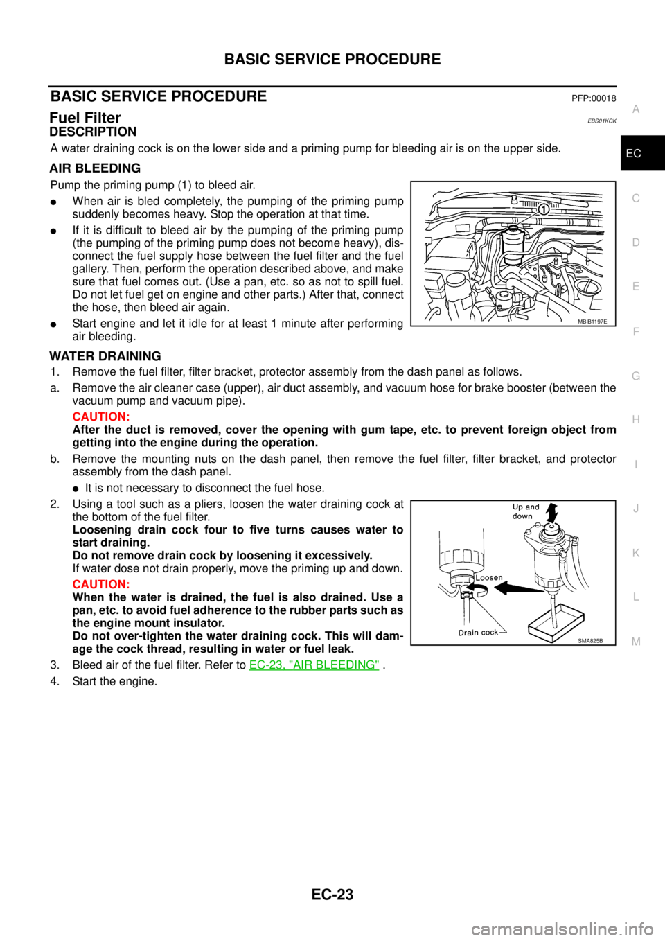
Pump the priming pump (1) to bleed air.
lWhen air is bled completely, the pumping of the priming pump
suddenly becomes heavy. Stop the operation at that time.
lIf it is difficult to bleed air by the pumping of the priming pump
(the pumping of the priming pump does not become heavy), dis-
connect the fuel supply hose between the fuel filter and the fuel
gallery. Then, perform the operation described above, and make
sure that fuel comes out. (Use a pan, etc. so as not to spill fuel.
Do not let fuel get on engine and other parts.) After that, connect
the hose, then bleed air again.
lStart engine and let it idle for at least 1 minute after performing
air bleeding.
WATER DRAINING
1. Remove the fuel filter, filter bracket, protector assembly from the dash panel as follows.
a. Remove the air cleaner case (upper), air duct assembly, and vacuum hose for brake booster (between the
vacuum pump and vacuum pipe).
CAUTION:
After the duct is removed, cover the opening with gum tape, etc. to prevent foreign object from
getting into the engine during the operation.
b. Remove the mounting nuts on the dash panel, then remove the fuel filter, filter bracket, and protector
assembly from the dash panel.
lIt is not necessary to disconnect the fuel hose.
2. Using a tool such as a pliers, loosen the water draining cock at
the bottom of the fuel filter.
Loosening drain cock four to five turns causes water to
start draining.
Do not remove drain cock by loosening it excessively.
If water dose not drain properly, move the priming up and down.
CAUTION:
When the water is drained, the fuel is also drained. Use a
pan, etc. to avoid fuel adherence to the rubber parts such as
the engine mount insulator.
Do not over-tighten the water draining cock. This will dam-
age the cock thread, resulting in water or fuel leak.
3. Bleed air of the fuel filter. Refer toEC-23, "
AIR BLEEDING".
4. Start the engine.
MBIB1197E
SMA825B
Page 1018 of 3171
EC-38
TROUBLE DIAGNOSIS
Basic Inspection
EBS01KCV
Precaution:
Perform Basic Inspection without electrical or mechanical loads applied;
lHeadlamp switch is OFF.
lOn vehicles equipped with daytime light systems, set lighting switch to the 1st position to light
only small lamps.
lAir conditioner switch is OFF.
lHeater fan switch is OFF.
lRear defogger switch is OFF.
lHeat up switch is OFF.
lSteering wheel is in the straight-ahead position, etc.
1.INSPECTION START
1. Check service records for any recent repairs that may indicate a related incident.
2. Check the current need for scheduled maintenance, especially for fuel filter and air cleaner filter. Refer to
MA-8, "
PERIODIC MAINTENANCE".
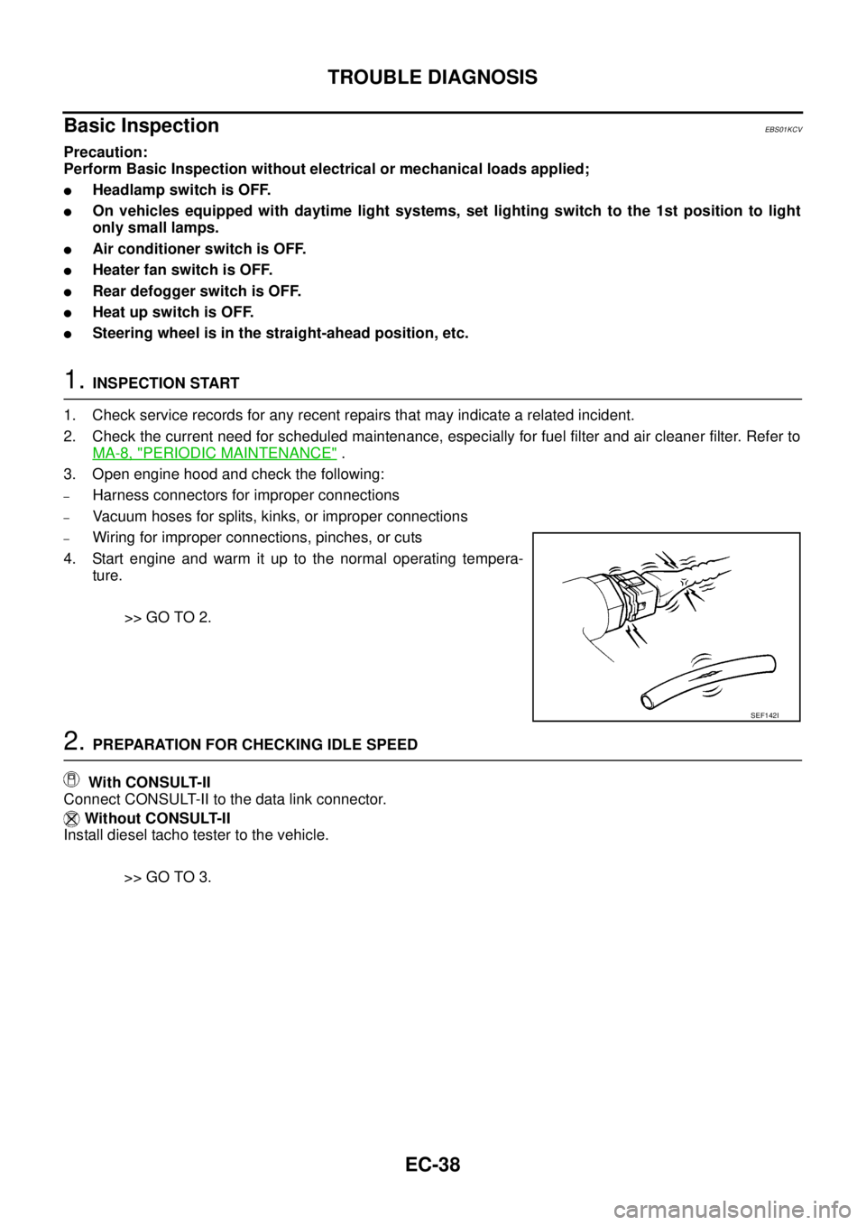
3. Open engine hood and check the following:
–Harness connectors for improper connections
–Vacuum hoses for splits, kinks, or improper connections
–Wiring for improper connections, pinches, or cuts
4. Start engine and warm it up to the normal operating tempera-
ture.
>> GO TO 2.
2.PREPARATION FOR CHECKING IDLE SPEED
With CONSULT-II
Connect CONSULT-II to the data link connector.
Without CONSULT-II
Install diesel tacho tester to the vehicle.
>> GO TO 3.
SEF142I