2005 NISSAN NAVARA air filter
[x] Cancel search: air filterPage 1019 of 3171
TROUBLE DIAGNOSIS
EC-39
C
D
E
F
G
H
I
J
K
L
MA
EC
3.CHECK IDLE SPEED
With CONSULT-II
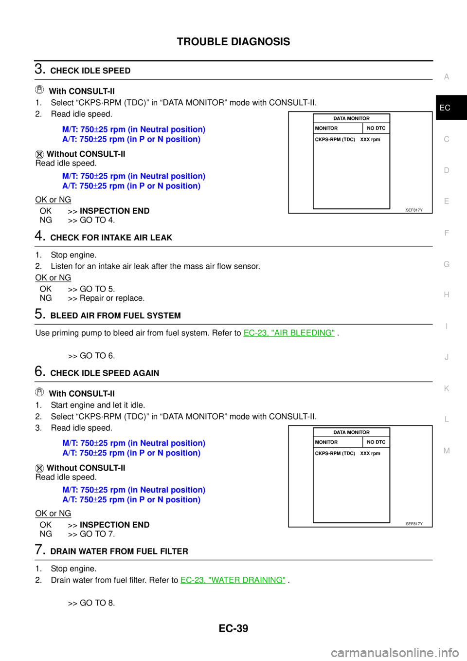
1. Select “CKPS·RPM (TDC)” in “DATA MONITOR” mode with CONSULT-II.
2. Read idle speed.
Without CONSULT-II
Read idle speed.
OK or NG
OK >>INSPECTION END
NG >> GO TO 4.
4.CHECK FOR INTAKE AIR LEAK
1. Stop engine.
2. Listen for an intake air leak after the mass air flow sensor.
OK or NG
OK >> GO TO 5.
NG >> Repair or replace.
5.BLEED AIR FROM FUEL SYSTEM
Use priming pump to bleed air from fuel system. Refer toEC-23, "
AIR BLEEDING".
>> GO TO 6.
6.CHECK IDLE SPEED AGAIN
With CONSULT-II
1. Start engine and let it idle.
2. Select “CKPS·RPM (TDC)” in “DATA MONITOR” mode with CONSULT-II.
3. Read idle speed.
Without CONSULT-II
Read idle speed.
OK or NG
OK >>INSPECTION END
NG >> GO TO 7.
7.DRAIN WATER FROM FUEL FILTER
1. Stop engine.
2. Drain water from fuel filter. Refer toEC-23, "
WATER DRAINING".
>> GO TO 8. M/T: 750±25 rpm (in Neutral position)
A/T: 750±25 rpm (in P or N position)
M/T: 750±25 rpm (in Neutral position)
A/T: 750±25 rpm (in P or N position)
SEF817Y
M/T: 750±25 rpm (in Neutral position)
A/T: 750±25 rpm (in P or N position)
M/T: 750±25 rpm (in Neutral position)
A/T: 750±25 rpm (in P or N position)
SEF817Y
Page 1020 of 3171
EC-40
TROUBLE DIAGNOSIS
8.CHECK IDLE SPEED AGAIN
With CONSULT-II
1. Start engine and let it idle.
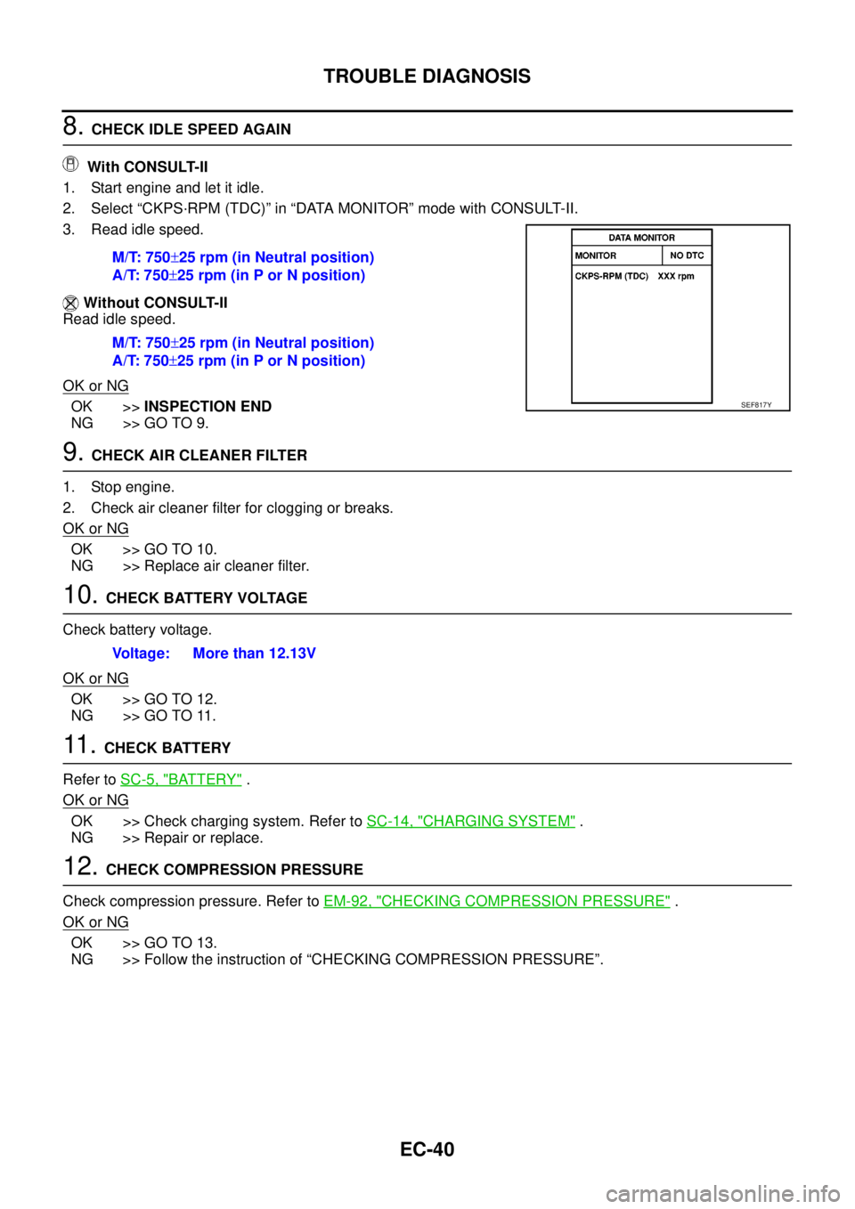
2. Select “CKPS·RPM (TDC)” in “DATA MONITOR” mode with CONSULT-II.
3. Read idle speed.
Without CONSULT-II
Read idle speed.
OK or NG
OK >>INSPECTION END
NG >> GO TO 9.
9.CHECK AIR CLEANER FILTER
1. Stop engine.
2. Check air cleaner filter for clogging or breaks.
OK or NG
OK >> GO TO 10.
NG >> Replace air cleaner filter.
10.CHECK BATTERY VOLTAGE
Check battery voltage.
OK or NG
OK >> GO TO 12.
NG >> GO TO 11.
11 .CHECK BATTERY
Refer toSC-5, "
BATTERY".
OK or NG
OK >> Check charging system. Refer toSC-14, "CHARGING SYSTEM".
NG >> Repair or replace.
12.CHECK COMPRESSION PRESSURE
Check compression pressure. Refer toEM-92, "
CHECKING COMPRESSION PRESSURE".
OK or NG
OK >> GO TO 13.
NG >> Follow the instruction of “CHECKING COMPRESSION PRESSURE”.M/T: 750±25 rpm (in Neutral position)
A/T: 750±25 rpm (in P or N position)
M/T: 750±25 rpm (in Neutral position)
A/T: 750±25 rpm (in P or N position)
SEF817Y
Voltage: More than 12.13V
Page 1294 of 3171
EC-314
INTAKE AIR CONTROL VALVE CONTROL SOLENOID VALVE
INTAKE AIR CONTROL VALVE CONTROL SOLENOID VALVE
PFP:16188
DescriptionEBS01KM5
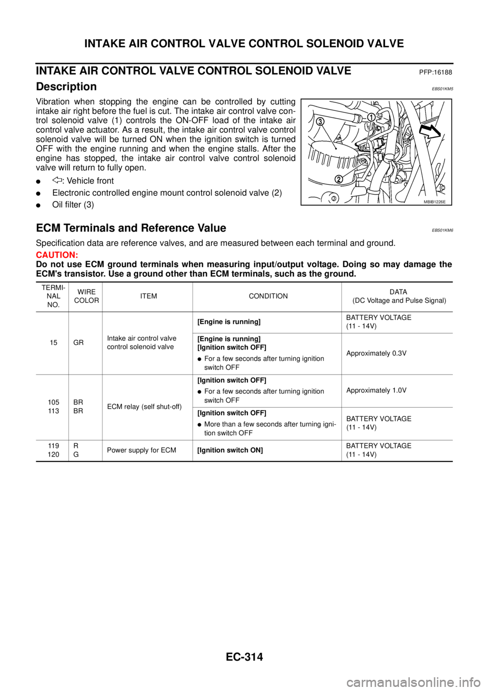
Vibration when stopping the engine can be controlled by cutting
intake air right before the fuel is cut. The intake air control valve con-
trol solenoid valve (1) controls the ON-OFF load of the intake air
control valve actuator. As a result, the intake air control valve control
solenoid valve will be turned ON when the ignition switch is turned
OFF with the engine running and when the engine stalls. After the
engine has stopped, the intake air control valve control solenoid
valve will return to fully open.
l: Vehicle front
lElectronic controlled engine mount control solenoid valve (2)
lOil filter (3)
ECM Terminals and Reference ValueEBS01KM6
Specification data are reference valves, and are measured between each terminal and ground.
CAUTION:
Do not use ECM ground terminals when measuring input/output voltage. Doing so may damage the
ECM's transistor. Use a ground other than ECM terminals, such as the ground.
MBIB1226E
TERMI-
NAL
NO.WIRE
COLORITEM CONDITIONDATA
(DC Voltage and Pulse Signal)
15 GRIntake air control valve
control solenoid valve[Engine is running]BATTERY VOLTAGE
(11 - 14V)
[Engine is running]
[Ignition switch OFF]
lFor a few seconds after turning ignition
switch OFFApproximately 0.3V
105
11 3BR
BRECM relay (self shut-off)[Ignition switch OFF]
lFor a few seconds after turning ignition
switch OFFApproximately 1.0V
[Ignition switch OFF]
lMore than a few seconds after turning igni-
tion switch OFFBATTERY VOLTAGE
(11 - 14V)
11 9
120R
GPower supply for ECM[Ignition switch ON]BATTERY VOLTAGE
(11 - 14V)
Page 1297 of 3171
INTAKE AIR CONTROL VALVE CONTROL SOLENOID VALVE
EC-317
C
D
E
F
G
H
I
J
K
L
MA
EC
4.CHECK INTAKE AIR CONTROL VALVE CONTROL SOLENOID VALVE POWER SUPPLY CIRCUIT
1. Turn ignition switch OFF.
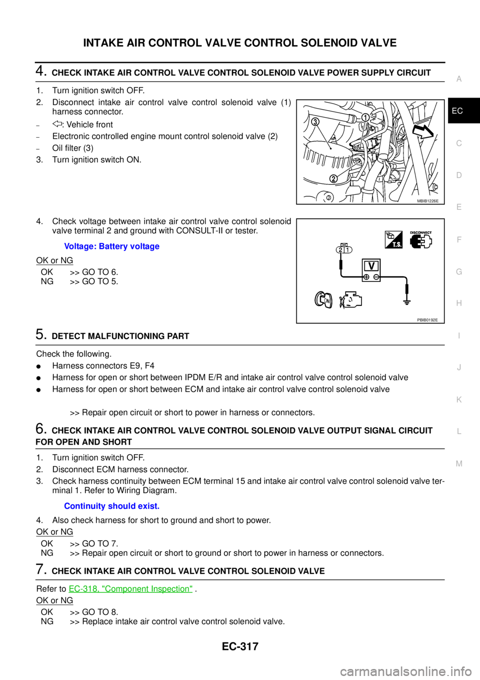
2. Disconnect intake air control valve control solenoid valve (1)
harness connector.
–: Vehicle front
–Electronic controlled engine mount control solenoid valve (2)
–Oil filter (3)
3. Turn ignition switch ON.
4. Check voltage between intake air control valve control solenoid
valve terminal 2 and ground with CONSULT-II or tester.
OK or NG
OK >> GO TO 6.
NG >> GO TO 5.
5.DETECT MALFUNCTIONING PART
Check the following.
lHarness connectors E9, F4
lHarness for open or short between IPDM E/R and intake air control valve control solenoid valve
lHarness for open or short between ECM and intake air control valve control solenoid valve
>> Repair open circuit or short to power in harness or connectors.
6.CHECK INTAKE AIR CONTROL VALVE CONTROL SOLENOID VALVE OUTPUT SIGNAL CIRCUIT
FOR OPEN AND SHORT
1. Turn ignition switch OFF.
2. Disconnect ECM harness connector.
3. Check harness continuity between ECM terminal 15 and intake air control valve control solenoid valve ter-
minal 1. Refer to Wiring Diagram.
4. Also check harness for short to ground and short to power.
OK or NG
OK >> GO TO 7.
NG >> Repair open circuit or short to ground or short to power in harness or connectors.
7.CHECK INTAKE AIR CONTROL VALVE CONTROL SOLENOID VALVE
Refer toEC-318, "
Component Inspection".
OK or NG
OK >> GO TO 8.
NG >> Replace intake air control valve control solenoid valve.
MBIB1226E
Voltage: Battery voltage
PBIB0192E
Continuity should exist.
Page 1298 of 3171
EC-318
INTAKE AIR CONTROL VALVE CONTROL SOLENOID VALVE
8.CHECK VACUUM PUMP
Refer toEM-42, "
VACUUM PUMP".
OK or NG
OK >> GO TO 9.
NG >> Replace vacuum pump assembly.
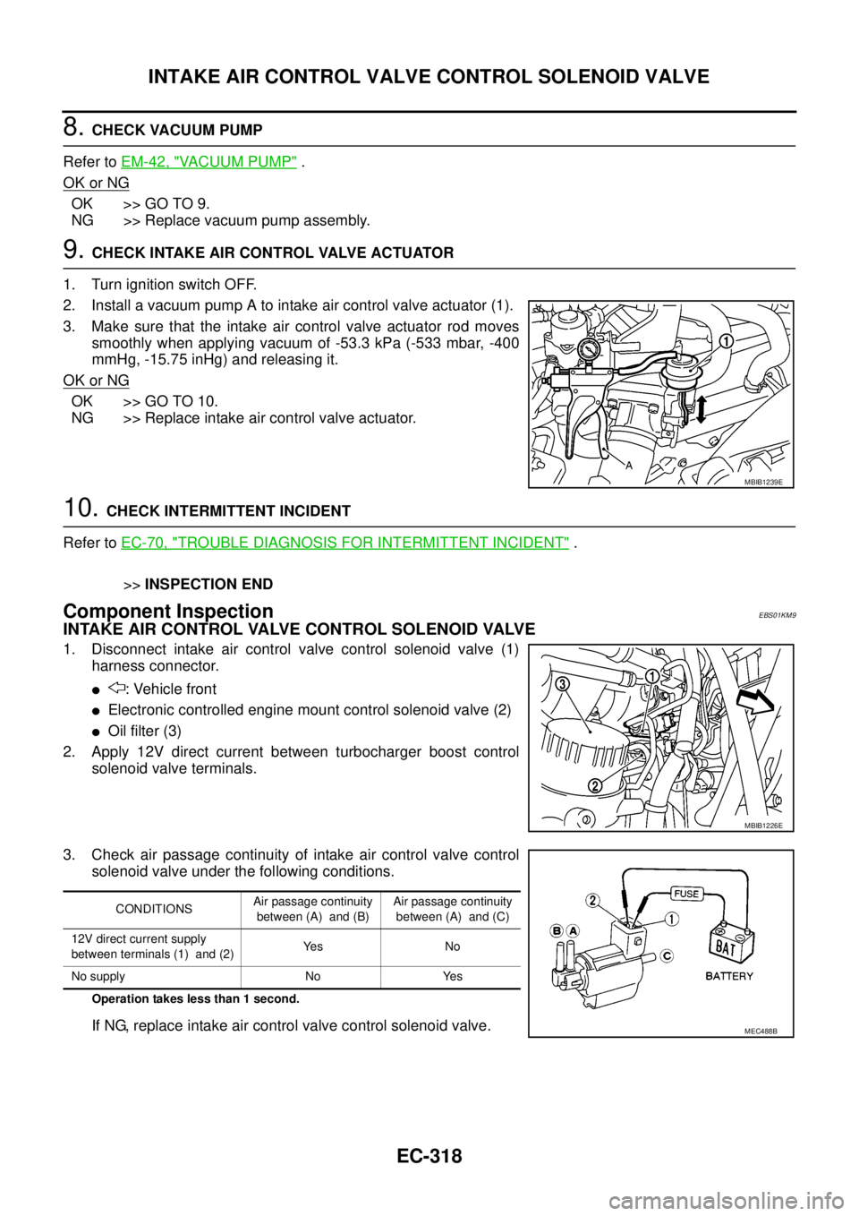
9.CHECK INTAKE AIR CONTROL VALVE ACTUATOR
1. Turn ignition switch OFF.
2. Install a vacuum pump A to intake air control valve actuator (1).
3. Make sure that the intake air control valve actuator rod moves
smoothly when applying vacuum of -53.3 kPa (-533 mbar, -400
mmHg, -15.75 inHg) and releasing it.
OK or NG
OK >> GO TO 10.
NG >> Replace intake air control valve actuator.
10.CHECK INTERMITTENT INCIDENT
Refer toEC-70, "
TROUBLE DIAGNOSIS FOR INTERMITTENT INCIDENT".
>>INSPECTION END
Component InspectionEBS01KM9
INTAKE AIR CONTROL VALVE CONTROL SOLENOID VALVE
1. Disconnect intake air control valve control solenoid valve (1)
harness connector.
l: Vehicle front
lElectronic controlled engine mount control solenoid valve (2)
lOil filter (3)
2. Apply 12V direct current between turbocharger boost control
solenoid valve terminals.
3. Check air passage continuity of intake air control valve control
solenoid valve under the following conditions.
Operation takes less than 1 second.
If NG, replace intake air control valve control solenoid valve.
MBIB1239E
MBIB1226E
CONDITIONSAir passage continuity
between (A) and (B)Air passage continuity
between (A) and (C)
12V direct current supply
between terminals (1) and (2)Ye s N o
No supply No Yes
MEC488B
Page 1383 of 3171
EM-1
ENGINE MECHANICAL
B ENGINE
CONTENTS
C
D
E
F
G
H
I
J
K
L
M
SECTIONEM
A
EM
ENGINE MECHANICAL
PRECAUTIONS .......................................................... 4
Precautions for Draining Engine Coolant ................. 4
Precautions for Disconnecting Fuel Piping .............. 4
Precautions for Removal and Disassembly ............. 4
Precautions for Inspection, Repair and Replace-
ment ......................................................................... 4
Precautions for Assembly and Installation ............... 4
Parts Requiring Angle Tightening ............................. 4
Precautions For Liquid Gasket ................................. 5
REMOVAL OF LIQUID GASKET .......................... 5
LIQUID GASKET APPLICATION PROCEDURE..... 5
PREPARATION ........................................................... 6
Special Service Tools ............................................... 6
Commercial Service Tools ........................................ 8
NOISE, VIBRATION AND HARSHNESS (NVH)
TROUBLESHOOTING .............................................. 10
NVH Troubleshooting — Engine Noise .................. 10
Use the Chart Below to Help You Find the Cause
of the Symptom. ...................................................... 11
DRIVE BELTS ........................................................... 12
Checking Drive Belts .............................................. 12
Deflection Adjustment ............................................ 13
POWER STEERING OIL PUMP BELT ............... 13
A/C COMPRESSOR, ALTERNATOR AND
WATER PUMP BELT .......................................... 14
Removal and Installation ........................................ 14
REMOVAL ........................................................... 14
INSTALLATION ................................................... 14
AIR CLEANER AND AIR DUCT ............................... 15
Components ........................................................... 15
Removal and Installation ........................................ 15
REMOVAL ........................................................... 15
INSTALLATION ................................................... 16
CHANGING AIR CLEANER FILTER ................... 17
CHARGE AIR COOLER ........................................... 18
Components ........................................................... 18
Removal and Installation ........................................ 18
REMOVAL ........................................................... 18
INSPECTION AFTER REMOVAL ....................... 19
INSTALLATION ................................................... 19INTAKE MANIFOLD ................................................. 20
Components ........................................................... 20
Removal and Installation ........................................ 21
REMOVAL ........................................................... 21
INSPECTION AFTER REMOVAL ....................... 22
INSTALLATION ................................................... 22
INSPECTION AFTER INSTALLATION ................ 25
CATALYST ................................................................ 26
Components ........................................................... 26
Removal and Installation ........................................ 26
REMOVAL ........................................................... 26
INSTALLATION ................................................... 27
TURBO CHARGER ................................................... 28
Components ........................................................... 28
Removal and Installation ........................................ 29
REMOVAL ........................................................... 29
INSPECTION AFTER REMOVAL ....................... 30
TROUBLE DIAGNOSIS OF TURBOCHARGER... 32
INSTALLATION ................................................... 33
EXHAUST MANIFOLD ............................................. 34
Components ........................................................... 34
Removal and Installation ........................................ 34
REMOVAL ........................................................... 34
INSPECTION AFTER REMOVAL ....................... 35
INSTALLATION ................................................... 35
INSPECTION AFTER INSTALLATION ................ 35
OIL PAN AND OIL STRAINER ................................. 36
Components ........................................................... 36
Removal and Installation ........................................ 36
REMOVAL ........................................................... 36
INSPECTION AFTER REMOVAL ....................... 38
INSTALLATION ................................................... 38
INSPECTION AFTER INSTALLATION ................ 40
GLOW PLUG ............................................................ 41
Components ........................................................... 41
Removal and Installation ........................................ 41
REMOVAL ........................................................... 41
INSTALLATION ................................................... 41
VACUUM PUMP ........................................................ 42
Page 1397 of 3171
AIR CLEANER AND AIR DUCT
EM-15
C
D
E
F
G
H
I
J
K
L
MA
EM
AIR CLEANER AND AIR DUCTPFP:16500
ComponentsEBS01EJC
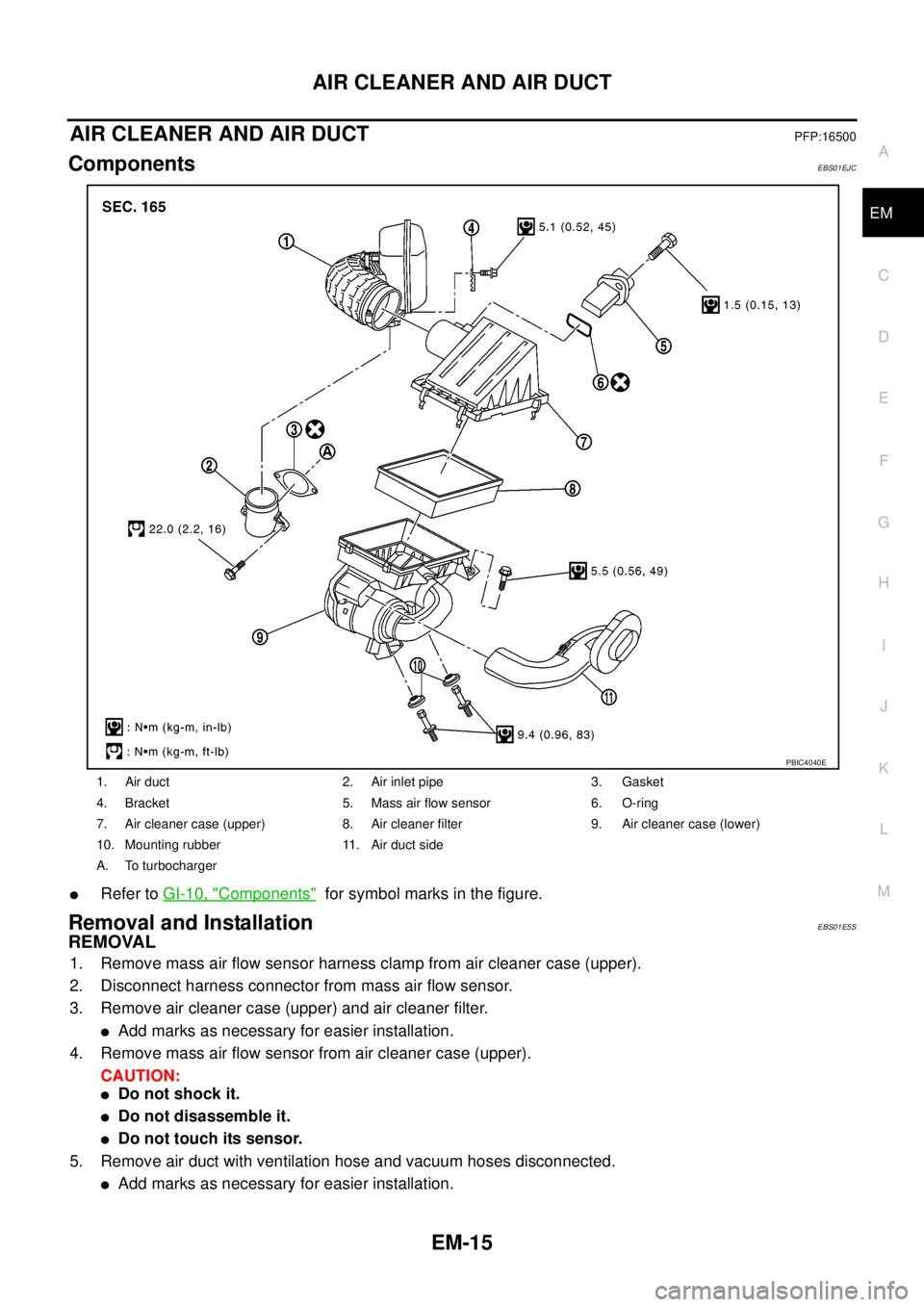
lRefer toGI-10, "Components"for symbol marks in the figure.
Removal and InstallationEBS01E5S
REMOVAL
1. Remove mass air flow sensor harness clamp from air cleaner case (upper).
2. Disconnect harness connector from mass air flow sensor.
3. Remove air cleaner case (upper) and air cleaner filter.
lAdd marks as necessary for easier installation.
4. Remove mass air flow sensor from air cleaner case (upper).
CAUTION:
lDo not shock it.
lDo not disassemble it.
lDo not touch its sensor.
5. Remove air duct with ventilation hose and vacuum hoses disconnected.
lAdd marks as necessary for easier installation.
1. Air duct 2. Air inlet pipe 3. Gasket
4. Bracket 5. Mass air flow sensor 6. O-ring
7. Air cleaner case (upper) 8. Air cleaner filter 9. Air cleaner case (lower)
10. Mounting rubber 11. Air duct side
A. To turbocharger
PBIC4040E
Page 1399 of 3171

AIR CLEANER AND AIR DUCT
EM-17
C
D
E
F
G
H
I
J
K
L
MA
EM
CHANGING AIR CLEANER FILTER
Removal
1. Remove mass air flow sensor harness clamp from air cleaner case (upper).
2. Disconnect harness connector from mass air flow sensor.
3. Unfasten clips and lift up air cleaner case (upper).
4. Remove air cleaner filter.
Installation
Installation is the reverse order of removal.