2005 NISSAN NAVARA air filter
[x] Cancel search: air filterPage 1403 of 3171
INTAKE MANIFOLD
EM-21
C
D
E
F
G
H
I
J
K
L
MA
EM
lRefer toGI-10, "Components"for symbol marks except in the above.
Removal and InstallationEBS01EJF
REMOVAL
WARNING:
To avoid the danger of being scalded, do not drain engine coolant when engine is hot.
1. Drain engine coolant. Refer toCO-7, "
Changing Engine Coolant".
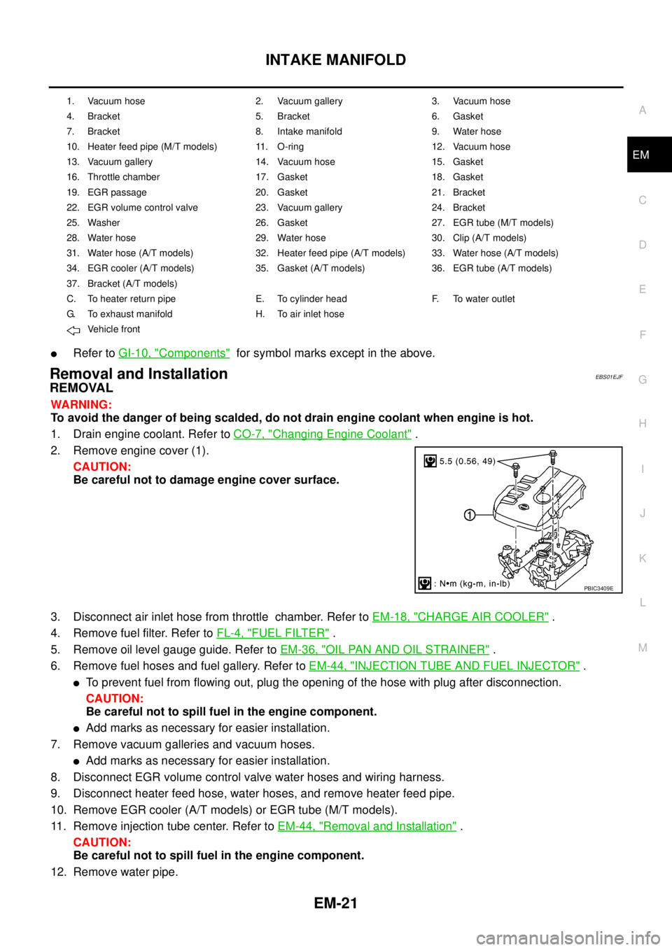
2. Remove engine cover (1).
CAUTION:
Be careful not to damage engine cover surface.
3. Disconnect air inlet hose from throttle chamber. Refer toEM-18, "
CHARGE AIR COOLER".
4. Remove fuel filter. Refer toFL-4, "
FUEL FILTER".
5. Remove oil level gauge guide. Refer toEM-36, "
OIL PAN AND OIL STRAINER".
6. Remove fuel hoses and fuel gallery. Refer toEM-44, "
INJECTION TUBE AND FUEL INJECTOR".
lTo prevent fuel from flowing out, plug the opening of the hose with plug after disconnection.
CAUTION:
Be careful not to spill fuel in the engine component.
lAdd marks as necessary for easier installation.
7. Remove vacuum galleries and vacuum hoses.
lAdd marks as necessary for easier installation.
8. Disconnect EGR volume control valve water hoses and wiring harness.
9. Disconnect heater feed hose, water hoses, and remove heater feed pipe.
10. Remove EGR cooler (A/T models) or EGR tube (M/T models).
11. Remove injection tube center. Refer toEM-44, "
Removal and Installation".
CAUTION:
Be careful not to spill fuel in the engine component.
12. Remove water pipe.
1. Vacuum hose 2. Vacuum gallery 3. Vacuum hose
4. Bracket 5. Bracket 6. Gasket
7. Bracket 8. Intake manifold 9. Water hose
10. Heater feed pipe (M/T models) 11. O-ring 12. Vacuum hose
13. Vacuum gallery 14. Vacuum hose 15. Gasket
16. Throttle chamber 17. Gasket 18. Gasket
19. EGR passage 20. Gasket 21. Bracket
22. EGR volume control valve 23. Vacuum gallery 24. Bracket
25. Washer 26. Gasket 27. EGR tube (M/T models)
28. Water hose 29. Water hose 30. Clip (A/T models)
31. Water hose (A/T models) 32. Heater feed pipe (A/T models) 33. Water hose (A/T models)
34. EGR cooler (A/T models) 35. Gasket (A/T models) 36. EGR tube (A/T models)
37. Bracket (A/T models)
C. To heater return pipe E. To cylinder head F. To water outlet
G. To exhaust manifold H. To air inlet hose
Vehicle front
PBIC3409E
Page 1429 of 3171
INJECTION TUBE AND FUEL INJECTOR
EM-47
C
D
E
F
G
H
I
J
K
L
MA
EM
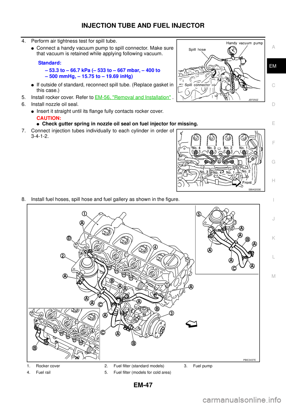
4. Perform air tightness test for spill tube.
lConnect a handy vacuum pump to spill connector. Make sure
that vacuum is retained while applying following vacuum.
lIf outside of standard, reconnect spill tube. (Replace gasket in
this case.)
5. Install rocker cover. Refer toEM-56, "
Removal and Installation".
6. Install nozzle oil seal.
lInsert it straight until its flange fully contacts rocker cover.
CAUTION:
lCheck gutter spring in nozzle oil seal on fuel injector for missing.
7. Connect injection tubes individually to each cylinder in order of
3-4-1-2.
8. Install fuel hoses, spill hose and fuel gallery as shown in the figure.Standard:
–53.3to–66.7kPa(–533to–667mbar,–400to
– 500 mmHg, – 15.75 to – 19.69 inHg)
JEF250Z
SBIA0203E
1. Rocker cover 2. Fuel filter (standard models) 3. Fuel pump
4. Fuel rail 5. Fuel filter (models for cold area)
PBIC3437E
Page 1478 of 3171
EM-96
CYLINDER HEAD
INSTALLATION
Before installation, remove old liquid gasket from mating surface of all liquid gasket applied parts.
1. Install cylinder head gasket.
lCylinder head gasket to be installed is selected by its thickness through the following procedure.
–When replacing gasket alone
• Install a gasket with same thickness as that of the one removed.
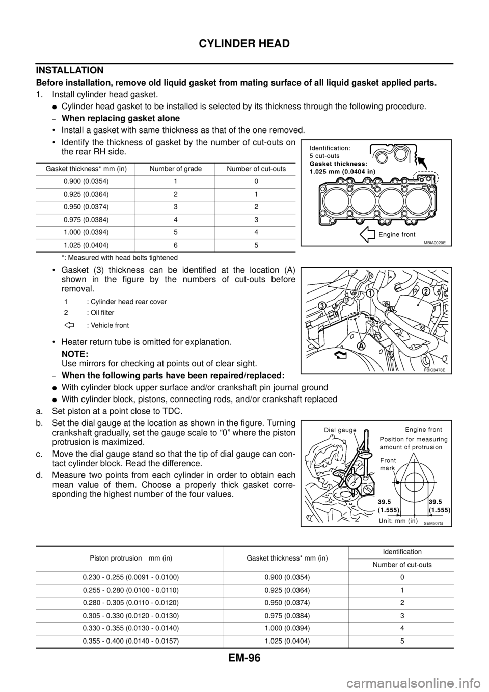
• Identify the thickness of gasket by the number of cut-outs on
the rear RH side.
*: Measured with head bolts tightened
• Gasket (3) thickness can be identified at the location (A)
shown in the figure by the numbers of cut-outs before
removal.
• Heater return tube is omitted for explanation.
NOTE:
Use mirrors for checking at points out of clear sight.
–When the following parts have been repaired/replaced:
lWith cylinder block upper surface and/or crankshaft pin journal ground
lWith cylinder block, pistons, connecting rods, and/or crankshaft replaced
a. Set piston at a point close to TDC.
b. Set the dial gauge at the location as shown in the figure. Turning
crankshaft gradually, set the gauge scale to “0” where the piston
protrusion is maximized.
c. Movethedialgaugestandsothatthetipofdialgaugecancon-
tact cylinder block. Read the difference.
d. Measure two points from each cylinder in order to obtain each
mean value of them. Choose a properly thick gasket corre-
sponding the highest number of the four values.
Gasket thickness* mm (in) Number of grade Number of cut-outs
0.900 (0.0354) 1 0
0.925 (0.0364) 2 1
0.950 (0.0374) 3 2
0.975 (0.0384) 4 3
1.000 (0.0394) 5 4
1.025 (0.0404) 6 5
1 : Cylinder head rear cover
2:Oilfilter
: Vehicle front
MBIA0020E
PBIC3478E
SEM507G
Piston protrusion mm (in) Gasket thickness* mm (in)Identification
Number of cut-outs
0.230 - 0.255 (0.0091 - 0.0100) 0.900 (0.0354) 0
0.255 - 0.280 (0.0100 - 0.0110) 0.925 (0.0364) 1
0.280 - 0.305 (0.0110 - 0.0120) 0.950 (0.0374) 2
0.305 - 0.330 (0.0120 - 0.0130) 0.975 (0.0384) 3
0.330 - 0.355 (0.0130 - 0.0140) 1.000 (0.0394) 4
0.355 - 0.400 (0.0140 - 0.0157) 1.025 (0.0404) 5
Page 1489 of 3171
ENGINE ASSEMBLY
EM-107
C
D
E
F
G
H
I
J
K
L
MA
EM
lFor supporting points for lifting and jacking point at rear axle, refer toGI-52, "Pantograph Jack,
Garage Jack and Safety Stand".
REMOVAL
Description of work
Remove transmission assembly from vehicle downward. Then hoist the engine from vehicle upward.
Preparation
1. Disconnect battery cable from negative terminal. Refer toSC-5, "BATTERY".
2. Drain engine coolant from radiator drain plug. Refer toCO-7, "
Changing Engine Coolant".
3. Remove the following parts.
lEngine undercover front, engine undercover middle, engine undercover rear; Refer toEI-15, "FRONT
BUMPER".
lHood assembly; Refer toBL-12, "HOOD".
lEngine cover; Refer toEM-20, "INTAKE MANIFOLD".
lDrive belts; Refer toEM-12, "DRIVE BELTS".
lCooling fan, fan coupling and water pump pulley; Refer toCO-19, "COOLING FAN".
lAir duct and air cleaner case; Refer toEM-15, "AIR CLEANER AND AIR DUCT".
lAir inlet tube and air inlet hose; Refer toEM-18, "CHARGE AIR COOLER".
lAlternator; Refer toSC-23, "Removal and Installation".
lRadiator, radiator shroud (upper and lower) and cooling fan assembly; Refer toCO-11, "RADIATOR"
andCO-19, "COOLING FAN".
4. Disconnect engine room harness from the engine side and set it aside for easier work.
5. Disconnect all the body-side vacuum hoses and air hoses at engine side.
Engine room RH
1. Disconnect fuel feed hose and return hose, and plug it to prevent fuel from draining. Refer toEM-44,
"INJECTION TUBE AND FUEL INJECTOR".
2. Remove fuel filter. Refer toFL-4, "
FUEL FILTER".
3. Disconnect heater hose, and install plug it to prevent engine coolant from draining. Refer toCO-23,
"THERMOSTAT AND WATER PIPING".
Engine room LH
1. Remove A/C compressor with piping connected from engine. Temporarily secure it on body with a rope to
avoid putting load on it. Refer toATC-142, "
Removal and Installation for Compressor"(automatic A/C
models) orMTC-122, "
Removal and Installation for Compressor"(manual A/C models).
Vehicle underbody
1. Remove exhaust front tube. Refer toEX-3, "Removal and Installation".
2. Remove front propeller shaft (4WD models) and rear propeller shaft. Refer toPR-3, "
FRONT PROPEL-
LER SHAFT"(4WD models) andPR-7, "REAR PROPELLER SHAFT".
3. Remove clutch operating cylinder from transmission, and move it aside (M/T models). Refer toMT-16,
"TRANSMISSION ASSEMBLY"andCL-11, "OPERATING CYLINDER".
4. Disconnect power steering fluid piping at a point between body and engine. Refer toPS-30, "
HYDRAULIC
LINE".
5. Remove starter motor. Refer toSC-31, "
Removal and Installation".
6. Remove transmission assembly. Refer toMT-16, "
TRANSMISSION ASSEMBLY"(M/T models) orAT-
247, "TRANSMISSION ASSEMBLY"(A/T models).
Page 1585 of 3171
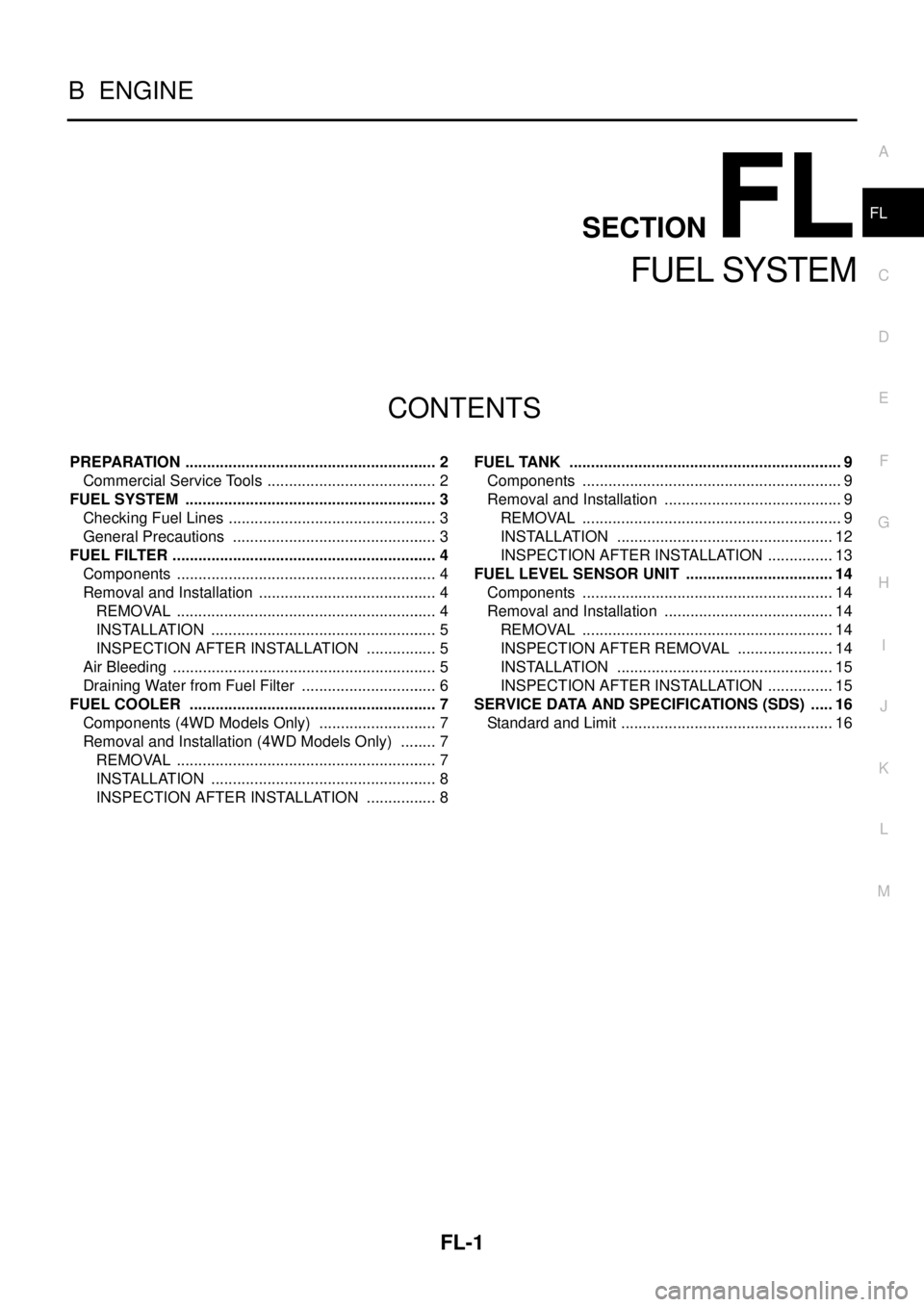
FL-1
FUEL SYSTEM
B ENGINE
CONTENTS
C
D
E
F
G
H
I
J
K
L
M
SECTIONFL
A
FL
FUEL SYSTEM
PREPARATION ........................................................... 2
Commercial Service Tools ........................................ 2
FUEL SYSTEM ........................................................... 3
Checking Fuel Lines ................................................. 3
General Precautions ................................................ 3
FUEL FILTER .............................................................. 4
Components ............................................................. 4
Removal and Installation .......................................... 4
REMOVAL ............................................................. 4
INSTALLATION ..................................................... 5
INSPECTION AFTER INSTALLATION ................. 5
Air Bleeding .............................................................. 5
Draining Water from Fuel Filter ................................ 6
FUEL COOLER .......................................................... 7
Components (4WD Models Only) ............................ 7
Removal and Installation (4WD Models Only) ......... 7
REMOVAL ............................................................. 7
INSTALLATION ..................................................... 8
INSPECTION AFTER INSTALLATION ................. 8FUEL TANK ................................................................ 9
Components ............................................................. 9
Removal and Installation .......................................... 9
REMOVAL ............................................................. 9
INSTALLATION ................................................... 12
INSPECTION AFTER INSTALLATION ................ 13
FUEL LEVEL SENSOR UNIT ................................... 14
Components ........................................................... 14
Removal and Installation ........................................ 14
REMOVAL ........................................................... 14
INSPECTION AFTER REMOVAL ....................... 14
INSTALLATION ................................................... 15
INSPECTION AFTER INSTALLATION ................ 15
SERVICE DATA AND SPECIFICATIONS (SDS) ...... 16
Standard and Limit .................................................. 16
Page 1589 of 3171
FUEL FILTER
FL-5
C
D
E
F
G
H
I
J
K
L
MA
FL
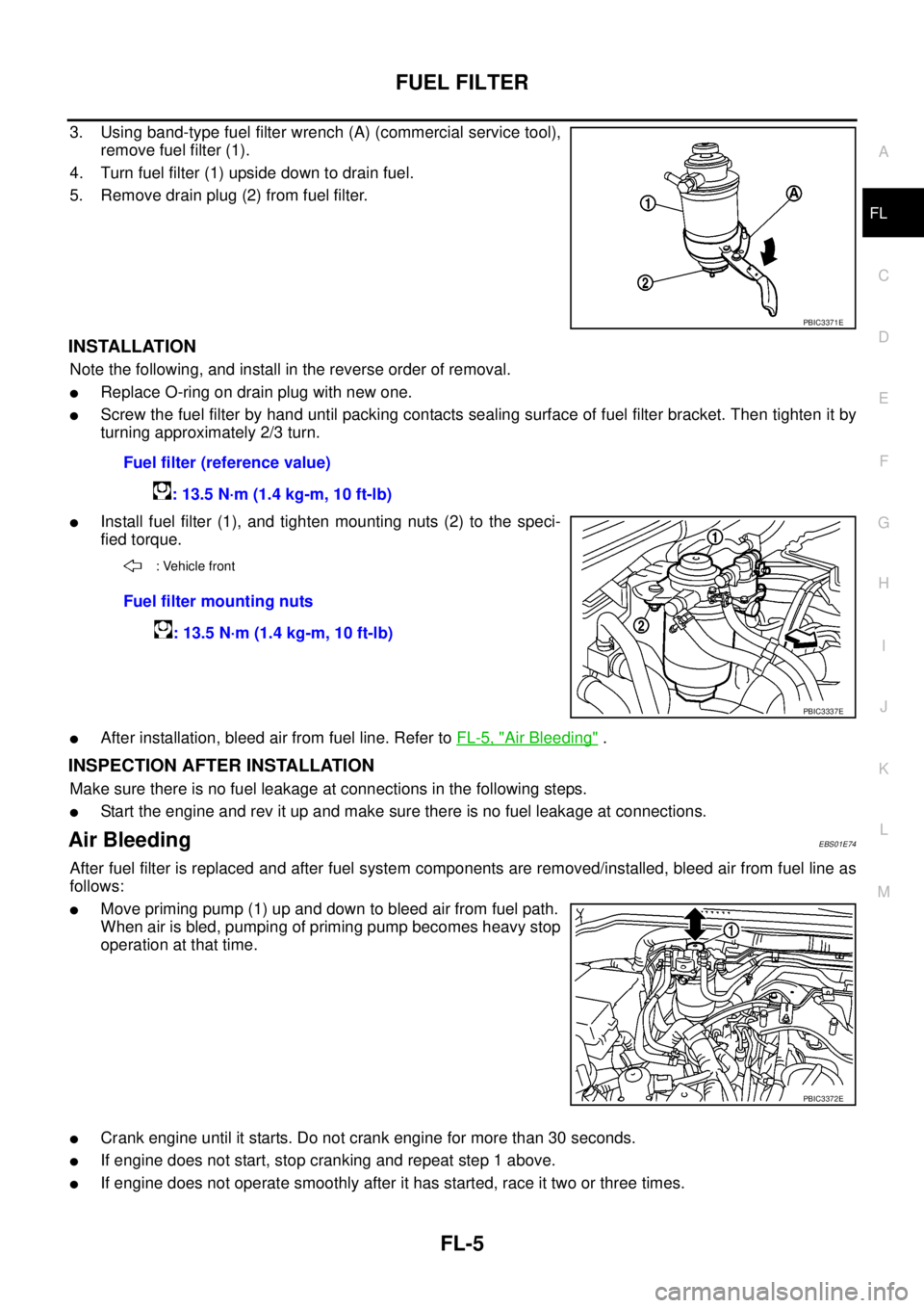
3. Using band-type fuel filter wrench (A) (commercial service tool),
remove fuel filter (1).
4. Turn fuel filter (1) upside down to drain fuel.
5. Remove drain plug (2) from fuel filter.
INSTALLATION
Note the following, and install in the reverse order of removal.
lReplace O-ring on drain plug with new one.
lScrew the fuel filter by hand until packing contacts sealing surface of fuel filter bracket. Then tighten it by
turning approximately 2/3 turn.
lInstall fuel filter (1), and tighten mounting nuts (2) to the speci-
fied torque.
lAfter installation, bleed air from fuel line. Refer toFL-5, "Air Bleeding".
INSPECTION AFTER INSTALLATION
Make sure there is no fuel leakage at connections in the following steps.
lStart the engine and rev it up and make sure there is no fuel leakage at connections.
Air BleedingEBS01E74
After fuel filter is replaced and after fuel system components are removed/installed, bleed air from fuel line as
follows:
lMove priming pump (1) up and down to bleed air from fuel path.
When air is bled, pumping of priming pump becomes heavy stop
operation at that time.
lCrank engine until it starts. Do not crank engine for more than 30 seconds.
lIf engine does not start, stop cranking and repeat step 1 above.
lIf engine does not operate smoothly after it has started, race it two or three times.
PBIC3371E
Fuel filter (reference value)
: 13.5 N·m (1.4 kg-m, 10 ft-lb)
: Vehicle front
Fuel filter mounting nuts
: 13.5 N·m (1.4 kg-m, 10 ft-lb)
PBIC3337E
PBIC3372E
Page 1590 of 3171

FL-6
FUEL FILTER
lIf air cannot be bled easily (pumping of priming pump does not become heavy), disconnect feed-side of
hose between fuel filter and electronically controlled fuel pump. After that, operate priming pump and con-
firm that fuel comes out.
CAUTION:
Prepare a tray to collect fuel. Prevent fuel from adhering to rubber parts, especially the engine
mounting insulator.
Draining Water from Fuel FilterEBS01E75
1. Prepare a tray (A) under the drain plug (1).
2. Loosen drain plug (1), and operate priming pump (2) to drain
water from fuel filter.
CAUTION:
lWater in filter is drained with fuel. Prepare larger capacity
pan than fuel filter volume.
lDrained water is mixed with fuel. Prevent fuel from adher-
ing to rubber parts such as engine mounting insulator.
3. Replace O-ring on drain plug with new one.
4. After draining, close drain plug to specified torque.
CAUTION:
If drain plug is tightened excessively, it may be damaged and fuel will leak.
5. Bleed air in fuel piping. Refer toFL-5, "
Air Bleeding".
6. Start engine and make sure there is no fuel leakage.Drain plug
: 1.3 N·m (0.13 kg-m, 12 in-lb)
PBIC3373E
Page 1630 of 3171
GI-8
PRECAUTIONS
lWhere there is a risk of eye contact, eye protection should be worn, for example, chemical goggles or face
shields; in addition an eye wash facility should be provided.
ENVIRONMENTAL PROTECTION PRECAUTIONS
Dispose of used oil and used oil filters through authorized waste disposal contractors to licensed waste dis-
posal sites, or to the waste oil reclamation trade. If in doubt, contact the local authority for advice on disposal
facilities.
It is illegal to pour used oil on to the ground, down sewers or drains, or into water sources.
The regulations concerning pollution vary between regions.
Precautions for Air ConditioningEAS001GR
Use an approved refrigerant recovery unit any time the air conditioning system must be discharged. Refer to
ATC/MTC section “HFC-134a (R-134a) Service Procedure”, “REFRIGERANT LINES” for specific instructions.