2005 NISSAN NAVARA air filter
[x] Cancel search: air filterPage 2300 of 3171

ENGINE MAINTENANCE
MA-25
C
D
E
F
G
H
I
J
K
MA
B
MA
Draining Water from Fuel FilterELS001JU
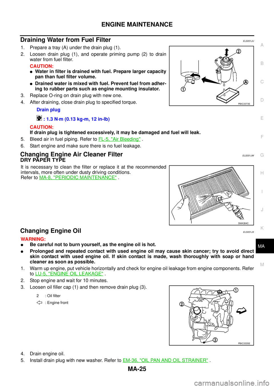
1. Prepare a tray (A) under the drain plug (1).
2. Loosen drain plug (1), and operate priming pump (2) to drain
water from fuel filter.
CAUTION:
lWater in filter is drained with fuel. Prepare larger capacity
pan than fuel filter volume.
lDrained water is mixed with fuel. Prevent fuel from adher-
ing to rubber parts such as engine mounting insulator.
3. Replace O-ring on drain plug with new one.
4. After draining, close drain plug to specified torque.
CAUTION:
If drain plug is tightened excessively, it may be damaged and fuel will leak.
5. Bleed air in fuel piping. Refer toFL-5, "
Air Bleeding".
6. Start engine and make sure there is no fuel leakage.
Changing Engine Air Cleaner FilterELS001JW
DRY PAPER TYPE
It is necessary to clean the filter or replace it at the recommended
intervals, more often under dusty driving conditions.
Refer toMA-8, "
PERIODIC MAINTENANCE".
Changing Engine OilELS001JX
WARNING:
lBe careful not to burn yourself, as the engine oil is hot.
lProlonged and repeated contact with used engine oil may cause skin cancer; try to avoid direct
skin contact with used engine oil. If skin contact is made, wash thoroughly with soap or hand
cleaner as soon as possible.
1. Warm up engine, put vehicle horizontally and check for engine oil leakage from engine components. Refer
toLU-5, "
ENGINE OIL LEAKAGE".
2. Stop engine and wait for 10 minutes.
3. Loosen oil filler cap (1) and then remove drain plug (3).
4. Drain engine oil.
5. Install drain plug with new washer. Refer toEM-36, "
OIL PAN AND OIL STRAINER". Drain plug
: 1.3 N·m (0.13 kg-m, 12 in-lb)
PBIC3373E
SMA384C
2 : Oil filter
: Engine front
PBIC3335E
Page 2389 of 3171

MTC-2
Schematic —LHD MODELS— ............................... 38
Wiring Diagram —A/C— —LHD MODELS— ......... 39
Schematic —RHD MODELS— ............................... 44
Wiring Diagram —A/C— —RHD MODELS— ......... 45
Front Air Control Terminals and Reference Value... 49
PIN CONNECTOR TERMINAL LAYOUT ............ 49
TERMINALS AND REFERENCE VALUE FOR
FRONT AIR CONTROL ....................................... 49
A/C System Self-diagnosis Function ...................... 51
DESCRIPTION .................................................... 51
Operational Check .................................................. 53
CHECKING BLOWER ......................................... 53
CHECKING DISCHARGE AIR ............................ 53
CHECKING RECIRCULATION ............................ 53
CHECKING TEMPERATURE DECREASE ......... 54
CHECKING TEMPERATURE INCREASE .......... 54
CHECK A/C SWITCH .......................................... 54
Power Supply and Ground Circuit for Front Air Con-
trol ........................................................................... 55
INSPECTION FLOW ........................................... 55
COMPONENT DESCRIPTION ............................ 56
DIAGNOSTIC PROCEDURE FOR A/C SYSTEM... 56
Mode Door Motor Circuit ........................................ 58
INSPECTION FLOW ........................................... 58
SYSTEM DESCRIPTION .................................... 59
COMPONENT DESCRIPTION ............................ 59
DIAGNOSTIC PROCEDURE FOR MODE
DOOR MOTOR ................................................... 59
Air Mix Door Motor Circuit ...................................... 63
INSPECTION FLOW ........................................... 63
SYSTEM DESCRIPTION .................................... 64
COMPONENT DESCRIPTION ............................ 64
DIAGNOSTIC PROCEDURE FOR AIR MIX
DOOR MOTOR (FRONT) .................................... 64
Intake Door Motor Circuit ........................................ 68
INSPECTION FLOW ........................................... 68
SYSTEM DESCRIPTION .................................... 69
COMPONENT DESCRIPTION ............................ 69
DIAGNOSTIC PROCEDURE FOR INTAKE
DOOR MOTOR ................................................... 69
Blower Motor Circuit ............................................... 71
INSPECTION FLOW ........................................... 71
SYSTEM DESCRIPTION .................................... 72
COMPONENT DESCRIPTION ............................ 72
DIAGNOSTIC PROCEDURE FOR BLOWER
MOTOR ............................................................... 73
COMPONENT INSPECTION .............................. 77
Magnet Clutch Circuit ............................................. 79
INSPECTION FLOW ........................................... 79
SYSTEM DESCRIPTION .................................... 80
DIAGNOSTIC PROCEDURE FOR MAGNET
CLUTCH .............................................................. 80
COMPONENT INSPECTION .............................. 85
Insufficient Cooling ................................................. 86
INSPECTION FLOW ........................................... 86
PERFORMANCE TEST DIAGNOSES ................ 87
PERFORMANCE CHART ................................... 89
TROUBLE DIAGNOSES FOR UNUSUAL PRES-
SURE ................................................................... 90Insufficient Heating ................................................. 93
INSPECTION FLOW ............................................ 93
Noise ....................................................................... 94
INSPECTION FLOW ............................................ 94
Self-diagnosis ......................................................... 95
INSPECTION FLOW ............................................ 95
Intake Sensor Circuit ............................................... 95
COMPONENT DESCRIPTION ............................ 95
DIAGNOSTIC PROCEDURE FOR INTAKE SEN-
SOR ..................................................................... 96
COMPONENT INSPECTION ............................... 97
CONTROL UNIT ........................................................ 98
Removal and Installation ......................................... 98
REMOVAL ............................................................ 98
INSTALLATION .................................................... 98
INTAKE SENSOR ...................................................... 99
Removal and Installation ......................................... 99
REMOVAL ............................................................ 99
INSTALLATION .................................................... 99
BLOWER MOTOR ...................................................100
Components ..........................................................100
Removal and Installation .......................................100
REMOVAL ..........................................................100
INSTALLATION ..................................................100
AIR CONDITIONER FILTER ...................................101
Removal and Installation .......................................101
FUNCTION ........................................................101
REPLACEMENT TIMING ..................................101
REPLACEMENT PROCEDURE ........................101
HEATER & COOLING UNIT ASSEMBLY ...............103
Components ..........................................................103
Removal and Installation .......................................105
REMOVAL ..........................................................105
INSTALLATION ..................................................105
HEATER CORE .......................................................106
Components ..........................................................106
Removal and Installation .......................................107
REMOVAL ..........................................................107
INSTALLATION ..................................................107
DEFROSTER DOOR MOTOR .................................108
Components ..........................................................108
Removal and Installation .......................................108
REMOVAL ..........................................................108
INSTALLATION ..................................................108
INTAKE DOOR MOTOR ..........................................109
Components ..........................................................109
Removal and Installation .......................................109
REMOVAL ..........................................................109
INSTALLATION ..................................................109
MODE DOOR MOTOR ............................................110
Components ..........................................................110
Removal and Installation .......................................110
REMOVAL ..........................................................110
INSTALLATION ..................................................110
AIR MIX DOOR MOTOR ......................................... 111
Components .......................................................... 111
Removal and Installation ....................................... 111
REMOVAL .......................................................... 111
INSTALLATION .................................................. 111
Page 2488 of 3171

AIR CONDITIONER FILTER
MTC-101
C
D
E
F
G
H
I
K
L
MA
B
MTC
AIR CONDITIONER FILTERPFP:27277
Removal and InstallationEJS005GW
FUNCTION
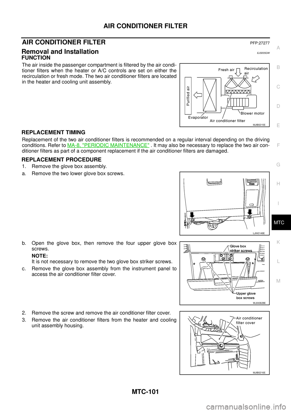
The air inside the passenger compartment is filtered by the air condi-
tioner filters when the heater or A/C controls are set on either the
recirculation or fresh mode. The two air conditioner filters are located
in the heater and cooling unit assembly.
REPLACEMENT TIMING
Replacement of the two air conditioner filters is recommended on a regular interval depending on the driving
conditions. Refer toMA-8, "
PERIODIC MAINTENANCE". It may also be necessary to replace the two air con-
ditioner filters as part of a component replacement if the air conditioner filters are damaged.
REPLACEMENT PROCEDURE
1. Remove the glove box assembly.
a. Remove the two lower glove box screws.
b. Open the glove box, then remove the four upper glove box
screws.
NOTE:
It is not necessary to remove the two glove box striker screws.
c. Remove the glove box assembly from the instrument panel to
access the air conditioner filter cover.
2. Remove the screw and remove the air conditioner filter cover.
3. Remove the air conditioner filters from the heater and cooling
unit assembly housing.
MJIB0215E
LJIA0146E
WJIA0628E
MJIB0216E
Page 2489 of 3171

MTC-102
AIR CONDITIONER FILTER
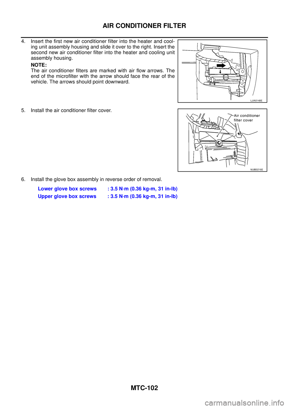
4. Insert the first new air conditioner filter into the heater and cool-
ing unit assembly housing and slide it over to the right. Insert the
second new air conditioner filter into the heater and cooling unit
assembly housing.
NOTE:
The air conditioner filters are marked with air flow arrows. The
end of the microfilter with the arrow should face the rear of the
vehicle. The arrows should point downward.
5. Install the air conditioner filter cover.
6. Install the glove box assembly in reverse order of removal.
LJIA0148E
MJIB0216E
Lower glove box screws : 3.5 N·m (0.36 kg-m, 31 in-lb)
Upper glove box screws : 3.5 N·m (0.36 kg-m, 31 in-lb)
Page 2494 of 3171

HEATER CORE
MTC-107
C
D
E
F
G
H
I
K
L
MA
B
MTC
Removal and InstallationEJS005H0
REMOVAL
1. Remove the heater and cooling unit assembly. Refer toMTC-103, "HEATER&COOLING UNIT ASSEM-
BLY".
2. Remove the four screws and remove the upper bracket.
3. Remove the four screws and remove the heater core cover.
4. Remove the heater core pipe bracket.
5. Remove the heater core.
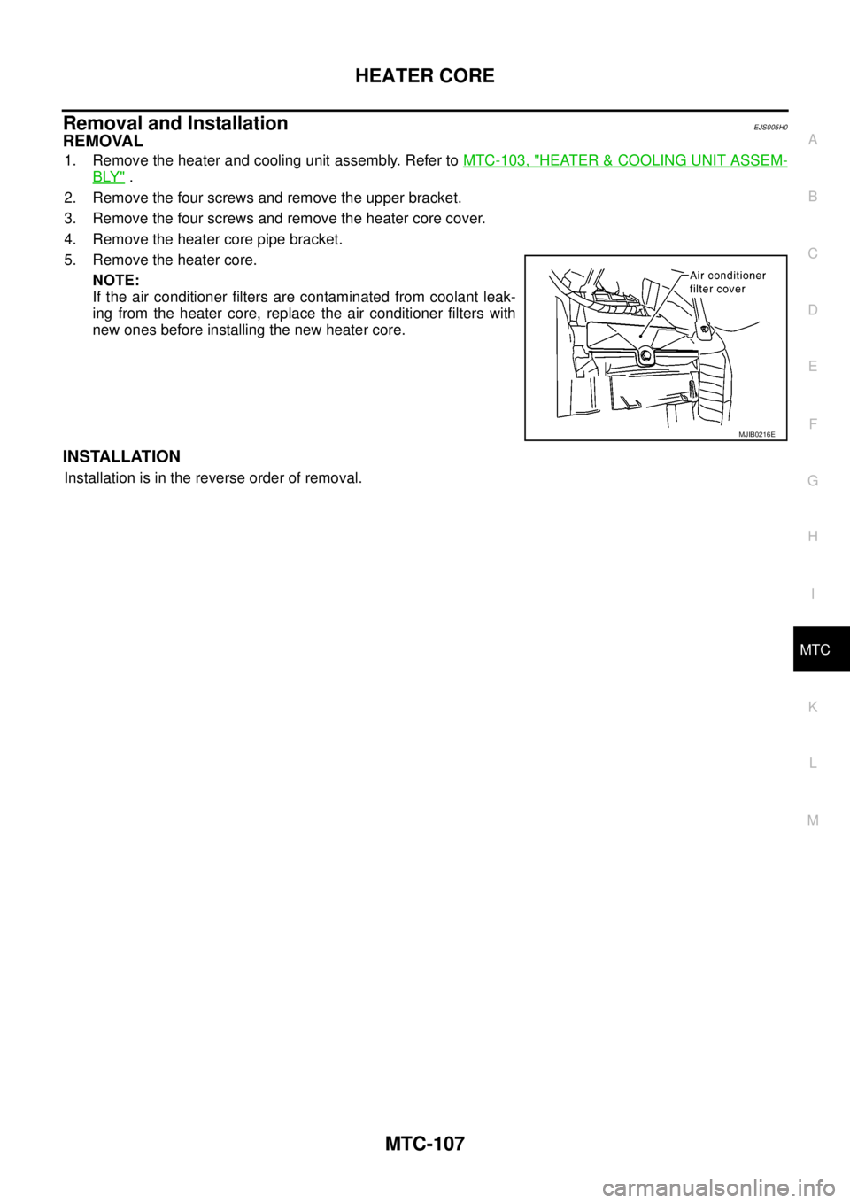
NOTE:
If the air conditioner filters are contaminated from coolant leak-
ing from the heater core, replace the air conditioner filters with
new ones before installing the new heater core.
INSTALLATION
Installation is in the reverse order of removal.
MJIB0216E