2005 MERCEDES-BENZ SPRINTER air condition
[x] Cancel search: air conditionPage 190 of 1232
MALFUNCTION INDICATOR
LAMP (MIL)
DESCRIPTION
A Malfunction Indicator Lamp (MIL) is standard
equipment on all instrument clusters. The MIL is
located near the lower edge of the instrument cluster, to
the right of the multi-function indicator display. The
MIL consists of the International Control and Display
Symbol icon for ªEngineº imprinted within a rectangu-
lar cutout in the opaque layer of the instrument cluster
overlay. The dark outer layer of the overlay prevents
the indicator from being clearly visible when it is not
illuminated. An amber Light Emitting Diode (LED)
behind the cutout in the opaque layer of the overlay
causes the icon to appear silhouetted against an amber
field through the translucent outer layer of the overlay
when the indicator is illuminated from behind by the
LED, which is soldered onto the instrument cluster elec-
tronic circuit board. The MIL is serviced as a unit with
the instrument cluster.
OPERATION
The Malfunction Indicator Lamp (MIL) gives an indi-
cation to the vehicle operator when the Engine Control
Module (ECM) has recorded a Diagnostic Trouble Code
(DTC) for an On-Board Diagnostics II (OBDII) emissions-
related circuit or component malfunction. The MIL is
controlled by a transistor on the instrument cluster cir-
cuit board based upon cluster programming and elec-
tronic messages received by the cluster from the ECM
over the Controller Area Network (CAN) data bus. The
MIL Light Emitting Diode (LED) is completely controlled
by the instrument cluster logic circuit, and that logic will
only allow this indicator to operate when the instrument
cluster detects that the ignition switch is in the On posi-
tion. Therefore, the LED will always be off when the
ignition switch is in any position except On. The LED
only illuminates when it is provided a path to ground by
the instrument cluster transistor. The instrument cluster
will turn on the MIL for the following reasons:
²Bulb Test- Each time the ignition switch is
turned to the On position the MIL is illuminated as a
bulb test. The indicator will remain illuminated until
the engine is started, or until the ignition switch is
turned to the Off position, whichever occurs first.
²MIL Lamp-On Message- Each time the clus-
ter receives a MIL lamp-on message from the ECM,
the indicator will be illuminated. The indicator will
remain illuminated until the detected fault is
repaired, or until the ignition switch is turned to the
Off position, whichever occurs first. For more infor-
mation on the ECM and the DTC set and reset
parameters, (Refer to 25 - EMISSIONS CONTROL -
OPERATION).²Communication Error- If the cluster receives
no lamp-on or lamp-off message from the ECM, the
MIL is illuminated by the instrument cluster. The
indicator remains controlled and illuminated by the
cluster until a valid lamp-on or lamp-off message is
received from the ECM.
The ECM continually monitors the fuel and emis-
sions system circuits and sensors to decide whether
the system is in good operating condition. The ECM
then sends the proper lamp-on or lamp-off messages
to the instrument cluster. If the instrument cluster
turns on the MIL after the bulb test, it may indicate
that a malfunction has occurred and that the fuel
and emissions systems may require service. For
proper diagnosis of the fuel and emissions systems,
the ECM, the CAN data bus, or the electronic mes-
sage inputs to the instrument cluster that control the
MIL, a DRBIIItscan tool is required. Refer to the
appropriate diagnostic information.
MULTI-FUNCTION INDICATOR
DESCRIPTION
A multi-function indicator is standard equipment on
all instrument clusters. The multi-function indicator is
located near the lower edge of the instrument cluster,
directly below the speedometer. The multi-function indi-
cator consists of a Liquid Crystal Display (LCD) unit
and four push button-controlled switches that are sol-
dered onto the instrument cluster electronic circuit
board. The LCD is visible through a large rectangular
cutout in the instrument cluster overlay, while the four
switch push buttons extend through a black plastic
switch bezel located on the cluster lens directly below
the LCD. The four multi-function indicator push buttons
allow the vehicle operator to configure and adjust sev-
eral of the display features. The buttons are labeled
from left to right: ªmiº (miles) or ªkmº (kilometers), an
icon depicting an analog clock face (clock), ª2º (minus),
and ª+º (plus).
The multi-function indicator LCD displays both
alpha-numeric characters and numerous icons to pro-
vide information to the vehicle operator. The indications
of the multi-function indicator are not visible when the
LCD is not illuminated. When illuminated the indica-
tions appear as dark characters and icons silhouetted
against an amber field. When the exterior lighting is
turned Off, the display is illuminated at maximum
brightness. When the exterior lighting is turned On the
display illumination level can be adjusted in concert
with the cluster general illumination lighting using the
ª+º (plus) and ª2º (minus) multi-function indicator push
buttons. The multi-function indicator LCD unit and
push button switches are serviced as a unit with the
instrument cluster.
8J - 20 INSTRUMENT CLUSTERVA
Page 244 of 1232
WARNING: ON VEHICLES EQUIPPED WITH AIR-
BAGS, DISABLE THE SUPPLEMENTAL RESTRAINT
SYSTEM BEFORE ATTEMPTING ANY STEERING
WHEEL, STEERING COLUMN, DRIVER AIRBAG,
PASSENGER AIRBAG, SEAT BELT TENSIONER, OR
INSTRUMENT PANEL COMPONENT DIAGNOSIS OR
SERVICE. DISCONNECT AND ISOLATE THE BAT-
TERY NEGATIVE (GROUND) CABLE, THEN WAIT
TWO MINUTES FOR THE SYSTEM CAPACITOR TO
DISCHARGE BEFORE PERFORMING FURTHER
DIAGNOSIS OR SERVICE. THIS IS THE ONLY SURE
WAY TO DISABLE THE SUPPLEMENTAL
RESTRAINT SYSTEM. FAILURE TO TAKE THE
PROPER PRECAUTIONS COULD RESULT IN ACCI-
DENTAL AIRBAG DEPLOYMENT AND POSSIBLE
PERSONAL INJURY.
STANDARD PROCEDURE
STANDARD PROCEDURE - HANDLING
NON-DEPLOYED SUPPLEMENTAL RESTRAINTS
At no time should any source of electricity be per-
mitted near the inflator on the back of a non-de-
ployed airbag or seat belt tensioner. When carrying a
non-deployed airbag, the trim cover or airbag cushion
side of the unit should be pointed away from the
body to minimize injury in the event of an accidental
deployment. If the airbag unit is placed on a bench or
any other surface, the trim cover or airbag cushion
side of the unit should be face up to minimize move-
ment in the event of an accidental deployment. When
handling a non-deployed seat belt tensioner, take
proper care to keep fingers out from under the
retractor cover and away from the seat belt webbing
where it exits from the retractor cover. In addition,
the supplemental restraint system should be dis-
armed whenever any steering wheel, steering col-
umn, seat belt tensioner, driver airbag, passenger
airbag, or instrument panel components require diag-
nosis or service. Failure to observe this warning
could result in accidental deployment and possible
personal injury.
All damaged, faulty or non-deployed airbags and
seat belt tensioners which are replaced on vehicles
are to be handled and disposed of properly. If an air-
bag or seat belt tensioner unit is faulty or damaged
and non-deployed, refer to the Hazardous Substance
Control System for proper disposal. Dispose of all
non-deployed and deployed airbags and seat belt ten-
sioners in a manner consistent with state, provincial,
local and federal regulations.
SUPPLEMENTAL RESTRAINT STORAGE
Airbags and seat belt tensioners must be stored in
their original, special container until they are used
for service. Also, they must be stored in a clean, dry
environment; away from sources of extreme heat,
sparks, and high electrical energy. Always place or
store any airbag on a surface with its trim cover or
airbag cushion side facing up, to minimize movement
in case of an accidental deployment.
STANDARD PROCEDURE - SERVICE AFTER A
SUPPLEMENTAL RESTRAINT DEPLOYMENT
Any vehicle which is to be returned to use follow-
ing a supplemental restraint deployment, must have
the deployed restraints replaced. In addition, if the
driver airbag has been deployed, the clockspring and
the steering wheel must be replaced. The seat belt
tensioners are deployed by the same signal that
deploys the driver and passenger airbags and must
also be replaced if either airbag has been deployed.
These components are not intended for reuse and
will be damaged or weakened as a result of a supple-
mental restraint deployment, which may or may not
be obvious during a visual inspection.
It is also critical that the mounting surfaces and/or
mounting brackets for the Airbag Control Module
(ACM) be closely inspected and restored to their orig-
inal conditions following any vehicle impact damage.
Because the ACM contains the impact sensor that is
used by the supplemental restraint system to moni-
tor or confirm the direction and severity of a vehicle
impact, improper orientation or insecure fastening of
this component may cause airbags not to deploy
when required, or to deploy when not required. All
other vehicle components should be closely inspected
following any supplemental restraint deployment, but
are to be replaced only as required by the extent of
the visible damage incurred.
CLEANUP PROCEDURE
Following a supplemental restraint deployment,
the vehicle interior will contain a powdery residue.
This residue consists primarily of harmless particu-
late by-products of the small pyrotechnic charge that
initiates the propellant used to deploy a supplemen-
tal restraint. However, this residue may also contain
traces of sodium hydroxide powder, a chemical
by-product of the propellant material that is used to
generate the inert gas that inflates the airbag. Since
sodium hydroxide powder can irritate the skin, eyes,
nose, or throat, be certain to wear safety glasses,
rubber gloves, and a long-sleeved shirt during
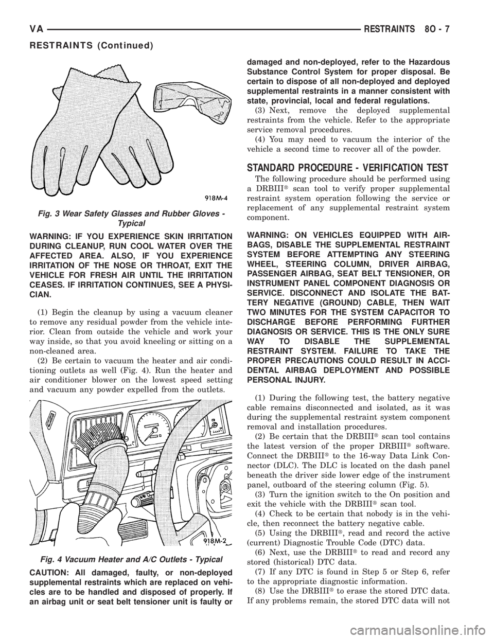
cleanup (Fig. 3).
8O - 6 RESTRAINTSVA
RESTRAINTS (Continued)
Page 245 of 1232
WARNING: IF YOU EXPERIENCE SKIN IRRITATION
DURING CLEANUP, RUN COOL WATER OVER THE
AFFECTED AREA. ALSO, IF YOU EXPERIENCE
IRRITATION OF THE NOSE OR THROAT, EXIT THE
VEHICLE FOR FRESH AIR UNTIL THE IRRITATION
CEASES. IF IRRITATION CONTINUES, SEE A PHYSI-
CIAN.
(1) Begin the cleanup by using a vacuum cleaner
to remove any residual powder from the vehicle inte-
rior. Clean from outside the vehicle and work your
way inside, so that you avoid kneeling or sitting on a
non-cleaned area.
(2) Be certain to vacuum the heater and air condi-
tioning outlets as well (Fig. 4). Run the heater and
air conditioner blower on the lowest speed setting
and vacuum any powder expelled from the outlets.
CAUTION: All damaged, faulty, or non-deployed
supplemental restraints which are replaced on vehi-
cles are to be handled and disposed of properly. If
an airbag unit or seat belt tensioner unit is faulty ordamaged and non-deployed, refer to the Hazardous
Substance Control System for proper disposal. Be
certain to dispose of all non-deployed and deployed
supplemental restraints in a manner consistent with
state, provincial, local and federal regulations.
(3) Next, remove the deployed supplemental
restraints from the vehicle. Refer to the appropriate
service removal procedures.
(4) You may need to vacuum the interior of the
vehicle a second time to recover all of the powder.
STANDARD PROCEDURE - VERIFICATION TEST
The following procedure should be performed using
a DRBIIItscan tool to verify proper supplemental
restraint system operation following the service or
replacement of any supplemental restraint system
component.
WARNING: ON VEHICLES EQUIPPED WITH AIR-
BAGS, DISABLE THE SUPPLEMENTAL RESTRAINT
SYSTEM BEFORE ATTEMPTING ANY STEERING
WHEEL, STEERING COLUMN, DRIVER AIRBAG,
PASSENGER AIRBAG, SEAT BELT TENSIONER, OR
INSTRUMENT PANEL COMPONENT DIAGNOSIS OR
SERVICE. DISCONNECT AND ISOLATE THE BAT-
TERY NEGATIVE (GROUND) CABLE, THEN WAIT
TWO MINUTES FOR THE SYSTEM CAPACITOR TO
DISCHARGE BEFORE PERFORMING FURTHER
DIAGNOSIS OR SERVICE. THIS IS THE ONLY SURE
WAY TO DISABLE THE SUPPLEMENTAL
RESTRAINT SYSTEM. FAILURE TO TAKE THE
PROPER PRECAUTIONS COULD RESULT IN ACCI-
DENTAL AIRBAG DEPLOYMENT AND POSSIBLE
PERSONAL INJURY.
(1) During the following test, the battery negative
cable remains disconnected and isolated, as it was
during the supplemental restraint system component
removal and installation procedures.
(2) Be certain that the DRBIIItscan tool contains
the latest version of the proper DRBIIItsoftware.
Connect the DRBIIItto the 16-way Data Link Con-
nector (DLC). The DLC is located on the dash panel
beneath the driver side lower edge of the instrument
panel, outboard of the steering column (Fig. 5).
(3) Turn the ignition switch to the On position and
exit the vehicle with the DRBIIItscan tool.
(4) Check to be certain that nobody is in the vehi-
cle, then reconnect the battery negative cable.
(5) Using the DRBIIIt, read and record the active
(current) Diagnostic Trouble Code (DTC) data.
(6) Next, use the DRBIIItto read and record any
stored (historical) DTC data.
(7) If any DTC is found in Step 5 or Step 6, refer
to the appropriate diagnostic information.
(8) Use the DRBIIItto erase the stored DTC data.
If any problems remain, the stored DTC data will not
Fig. 3 Wear Safety Glasses and Rubber Gloves -
Typical
Fig. 4 Vacuum Heater and A/C Outlets - Typical
VARESTRAINTS 8O - 7
RESTRAINTS (Continued)
Page 247 of 1232
an electronic impact sensor, and an energy storage
capacitor. The ACM housing has three integral
mounting tabs. A stamped metal cover plate is per-
manently secured to the bottom of the ACM housing
to enclose and protect the internal electronic circuitry
and components. An arrow printed on a label on the
top of the ACM housing near the rear provides a
visual verification of the proper orientation of the
unit, and should always be pointed toward the front
of the vehicle. A molded plastic electrical connector
receptacle containing numerous terminal pins is inte-
gral to the left facing side of the ACM housing. These
terminal pins connect the ACM to the vehicle electri-
cal system through a dedicated take out and connec-
tor of the vehicle wire harness.
The impact sensor internal to the ACM is cali-
brated for the specific vehicle, and is only serviced as
a unit with the ACM. The ACM cannot be repaired or
adjusted and, if damaged or faulty, it must be
replaced.
OPERATION
The microprocessor in the Airbag Control Module
(ACM) contains the supplemental restraint system
logic circuits and controls all of the supplemental
restraint system components. The ACM uses
On-Board Diagnostics (OBD) and can communicate
with the DRBIIItscan tool using a diagnostic Serial
Communication Interface (SCI) data bus line for sup-
plemental restraint system programming or diagno-
sis and testing through the 16-way Data Link
Connector (DLC) located on the dash panel below the
driver side end of the instrument panel. A hard wired
output from the ACM is used for control of the airbag
indicator in the ElectroMechanical Instrument Clus-
ter (EMIC). (Refer to 8 - ELECTRICAL/INSTRU-
MENT CLUSTER/AIRBAG INDICATOR -
OPERATION).
The ACM microprocessor continuously monitors all
of the supplemental restraint system electrical cir-
cuits to determine the system readiness. If the ACM
detects a monitored system fault, it sets an appropri-
ate Diagnostic Trouble Code (DTC) and sends an out-
put to the EMIC to turn on the airbag indicator. The
ACM illuminates the indicator for about four seconds
each time the ignition switch is turned to the On
position as a bulb test. If the indicator remains illu-
minated for about ten seconds after the ignition
switch is turned to the On position, the ACM has
detected a non-critical fault that poses no danger to
the vehicle occupants. If the airbag indicator illumi-
nates solid (not flashing) while driving or stays on
longer than ten seconds following the bulb test, the
ACM has detected a critical fault that may cause the
airbags not to deploy when required or to deploy
when not required. An active fault only remains forthe duration of the fault, or in some cases, for the
duration of the current ignition switch cycle, while a
stored fault causes a DTC to be stored in memory by
the ACM.
The ACM receives battery current through a fused
ignition switch output circuit. The ACM receives
ground through a ground circuit and take out of the
vehicle wire harness. This take out has an eyelet ter-
minal connector secured by a nut to a ground stud on
the floor panel directly below the ACM within the
driver side seat riser. A case ground is also provided
for the ACM through a ground circuit and eyelet ter-
minal connector secured under the left rear ACM
mounting screw. These connections allow the ACM to
be operational whenever the ignition switch is in the
On position. The ACM also contains an energy-stor-
age capacitor. When the ignition switch is in the On
position, this capacitor is continually being charged
with enough electrical energy to deploy the supple-
mental restraint components for up to one second fol-
lowing a battery disconnect or failure. The purpose of
the capacitor is to provide backup supplemental
restraint system protection in case there is a loss of
battery current supply to the ACM during an impact.
An electronic impact sensor is contained within the
ACM. The electronic impact sensor is an accelerome-
ter that senses the rate of vehicle deceleration, which
provides verification of the direction and severity of
an impact. A pre-programmed decision algorithm in
the ACM microprocessor determines when the decel-
eration rate as signaled by the impact sensor indi-
cates an impact that is severe enough to require
supplemental restraint system protection. When the
programmed conditions are met, the ACM sends the
proper electrical signals to deploy the seat belt ten-
sioners and front airbags.
The ACM also provides a hard wired electrical
crash signal output following a supplemental
restraint deployment event. This output is used to
signal other electronic modules in the vehicle to pro-
vide their enhanced accident response features,
which include automatically disabling the engine
from running and unlocking all of the doors. How-
ever, these responses are each dependent upon the
circuits, components, and modules controlling these
features remaining intact from collateral damage
incurred during the vehicle impact.
A single ACM is used for all variations of the sup-
plemental restraint system available in this vehicle.
This ACM is programmable and in order to function
properly it must be programmed for the correct vehi-
cle supplemental restraint system equipment using
an initialization procedure. The initialization proce-
dure requires the use of a DRBIIItscan tool. Refer to
the appropriate diagnostic information. The hard
wired inputs and outputs for the ACM may be diag-
VARESTRAINTS 8O - 9
AIRBAG CONTROL MODULE (Continued)
Page 270 of 1232
lar steel housing, a piston, a cable, a torsion bar, and
a small pyrotechnically activated gas generator. All of
these components are located on one side of the
retractor spool on the outside of the retractor housing
except for the torsion bar, which serves as the spin-
dle upon which the retractor spool rotates. The seat
belt tensioner is controlled by the Airbag Control
Module (ACM) and is connected to the vehicle elec-
trical system through a dedicated take out of the
vehicle wire harness by a keyed, snap-fit molded
plastic connector insulator to ensure a secure connec-
tion.
The seat belt tensioner cannot be repaired and, if
faulty or damaged, the entire front seat belt and
retractor unit must be replaced. If the front airbags
have been deployed, the seat belt tensioners have
also been deployed. The seat belt tensioner is not
intended for reuse and must be replaced following a
deployment. A growling or grinding sound while
attempting to operate the seat belt retractor is a sure
indication that the seat belt tensioner has been
deployed and requires replacement. (Refer to 8 -
ELECTRICAL/RESTRAINTS/FRONT SEAT BELT &
RETRACTOR - REMOVAL).
OPERATION
The seat belt tensioners are deployed in conjunc-
tion with the airbags by a signal generated by the
Airbag Control Module (ACM) through the driver and
passenger seat belt tensioner line 1 and line 2 (or
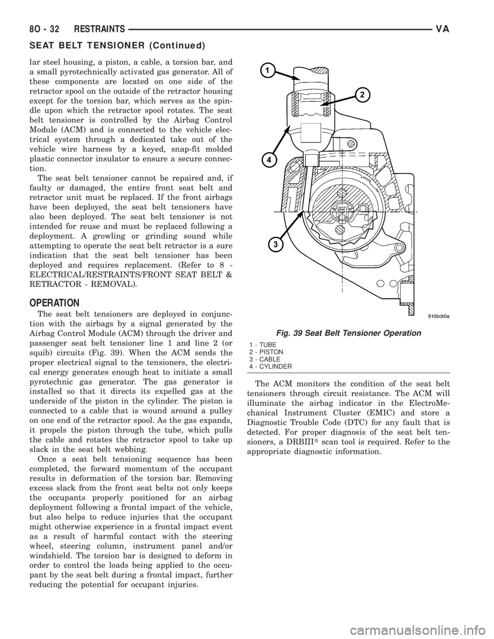
squib) circuits (Fig. 39). When the ACM sends the
proper electrical signal to the tensioners, the electri-
cal energy generates enough heat to initiate a small
pyrotechnic gas generator. The gas generator is
installed so that it directs its expelled gas at the
underside of the piston in the cylinder. The piston is
connected to a cable that is wound around a pulley
on one end of the retractor spool. As the gas expands,
it propels the piston through the tube, which pulls
the cable and rotates the retractor spool to take up
slack in the seat belt webbing.
Once a seat belt tensioning sequence has been
completed, the forward momentum of the occupant
results in deformation of the torsion bar. Removing
excess slack from the front seat belts not only keeps
the occupants properly positioned for an airbag
deployment following a frontal impact of the vehicle,
but also helps to reduce injuries that the occupant
might otherwise experience in a frontal impact event
as a result of harmful contact with the steering
wheel, steering column, instrument panel and/or
windshield. The torsion bar is designed to deform in
order to control the loads being applied to the occu-
pant by the seat belt during a frontal impact, further
reducing the potential for occupant injuries.The ACM monitors the condition of the seat belt
tensioners through circuit resistance. The ACM will
illuminate the airbag indicator in the ElectroMe-
chanical Instrument Cluster (EMIC) and store a
Diagnostic Trouble Code (DTC) for any fault that is
detected. For proper diagnosis of the seat belt ten-
sioners, a DRBIIItscan tool is required. Refer to the
appropriate diagnostic information.
Fig. 39 Seat Belt Tensioner Operation
1 - TUBE
2 - PISTON
3 - CABLE
4 - CYLINDER
8O - 32 RESTRAINTSVA
SEAT BELT TENSIONER (Continued)
Page 285 of 1232
The longer blade is installed on the left (driver) side
of the windshield.
²Wiper Linkage- The wiper pivots are the only
visible components of the wiper linkage. The remain-
der of the linkage is concealed within the engine
compartment just behind the hood opening. The
wiper linkage module includes the two wiper drive
links, the wiper motor crank arm, the two wiper piv-
ots, and the linkage and motor mounting bracket.
²Wiper Motor- The wiper motor is secured to
the wiper linkage module bracket on the underside of
the cowl panel within the engine compartment. The
wiper motor output shaft and crank arm extend
through a clearance hole in the mounting bracket,
where they are connected to a crank arm that drives
the wiper linkage.
²Wiper Relay- The wiper relay is located in a
dedicated receptacle on the lower left surface of the
fuse block underneath the steering column behind
the fuse access panel and the steering column open-
ing panel.
²Wiper, Turn Signals, Engine Start Control
Module- The wiper, turn signals and engine start
control module is integral to the fuse block located
underneath the steering column. The fuse block is
concealed behind the fuse access panel and the steer-
ing column opening panel, where it is secured with
screws to the steering column. The wiper, turn sig-
nals and engine start control module contains the
intermittent wipe logic circuitry, which includes
active electronic elements that allow it to provide the
intermittent wipe delay and the wipe-after-wash fea-
tures of the intermittent wipe system based upon
numerous hard wired inputs, then provides the
proper programmed hard wired control output to
operate the wiper motor through the wiper relay.
Hard wired circuitry connects the wiper and
washer system components to the electrical system of
the vehicle. These hard wired circuits are integral to
several wire harnesses, which are routed throughout
the vehicle and retained by many different methods.
These circuits may be connected to each other, to the
vehicle electrical system and to the wiper and washer
system components through the use of a combination
of soldered splices, splice block connectors, and many
different types of wire harness terminal connectors
and insulators. Refer to the appropriate wiring infor-
mation. The wiring information includes wiring dia-
grams, proper wire and connector repair procedures,
further details on wire harness routing and reten-
tion, as well as pin-out and location views for the
various wire harness connectors, splices and grounds.OPERATING MODES
The components of the wiper and washer system
are designed to provide the following operating
modes:
²Continuous Wipe Mode- The two-speed wiper
motor, the internal circuitry of the multi-function
switch, and the wiper relay work in concert to pro-
vide two continuous wipe cycles, low speed or high
speed.
²Intermittent Wipe Mode- The internal cir-
cuitry of the multi-function switch, the intermittent
wipe circuitry of the wiper, turn signals and engine
start control module in the fuse block, and the wiper
relay work in concert to provide an intermittent wipe
mode with a single, fixed delay interval.
²Pulse Wipe Mode- The internal circuitry of
the multi-function switch and the wiper relay work
in concert to provide a pulse wipe mode that will
allow the wiper motor to be operated for a single,
complete wipe cycle.
²Washer Mode- When the washer system is
activated with the multi-function switch while the
wiper system is operating, washer fluid will be dis-
pensed onto the windshield glass through the washer
nozzles for as long as the washer pump/motor is
energized.
²Wipe-After-Wash Mode- The intermittent
wipe circuitry of the wiper, turn signals and engine
start control module in the fuse block, and the wiper
relay provide a wipe-after-wash feature. If the wipers
are turned Off, this feature will operate the washer
pump/motor and the wipers for as long as the washer
system is activated, then provide several additional
wipe cycles after the washer system is deactivated
before parking the wiper blades near the base of the
windshield.
OPERATION
The wiper and washer system is designed to pro-
vide the vehicle operator with a convenient, safe, and
reliable means of maintaining visibility through the
windshield glass. The various components of this sys-
tem are designed to convert electrical energy pro-
duced by the vehicle electrical system into the
mechanical action of the wiper blades to wipe the
outside surface of the glass, as well as into the
hydraulic action of the washer system to apply
washer fluid stored in an on-board reservoir to the
area of the glass to be wiped. When combined, these
components provide the means to effectively main-
tain clear visibility for the vehicle operator by remov-
ing excess accumulations of rain, snow, bugs, mud, or
other minor debris from the outside windshield glass
surface that might be encountered while driving the
vehicle under numerous types of inclement operating
conditions.
VAWIPERS/WASHERS 8R - 3
WIPERS/WASHERS (Continued)
Page 289 of 1232
CHECK VALVE
DESCRIPTION
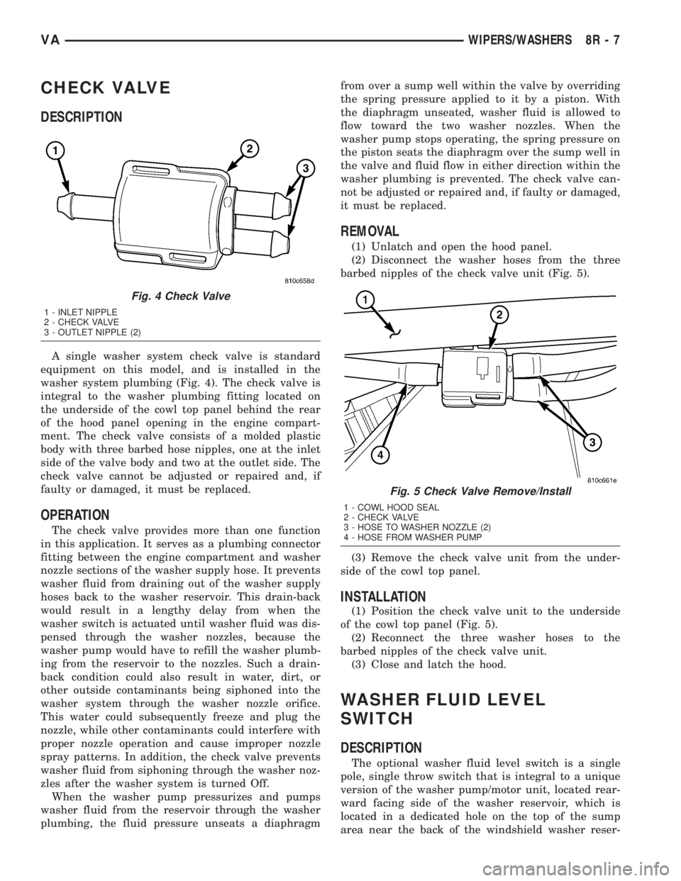
A single washer system check valve is standard
equipment on this model, and is installed in the
washer system plumbing (Fig. 4). The check valve is
integral to the washer plumbing fitting located on
the underside of the cowl top panel behind the rear
of the hood panel opening in the engine compart-
ment. The check valve consists of a molded plastic
body with three barbed hose nipples, one at the inlet
side of the valve body and two at the outlet side. The
check valve cannot be adjusted or repaired and, if
faulty or damaged, it must be replaced.
OPERATION
The check valve provides more than one function
in this application. It serves as a plumbing connector
fitting between the engine compartment and washer
nozzle sections of the washer supply hose. It prevents
washer fluid from draining out of the washer supply
hoses back to the washer reservoir. This drain-back
would result in a lengthy delay from when the
washer switch is actuated until washer fluid was dis-
pensed through the washer nozzles, because the
washer pump would have to refill the washer plumb-
ing from the reservoir to the nozzles. Such a drain-
back condition could also result in water, dirt, or
other outside contaminants being siphoned into the
washer system through the washer nozzle orifice.
This water could subsequently freeze and plug the
nozzle, while other contaminants could interfere with
proper nozzle operation and cause improper nozzle
spray patterns. In addition, the check valve prevents
washer fluid from siphoning through the washer noz-
zles after the washer system is turned Off.
When the washer pump pressurizes and pumps
washer fluid from the reservoir through the washer
plumbing, the fluid pressure unseats a diaphragmfrom over a sump well within the valve by overriding
the spring pressure applied to it by a piston. With
the diaphragm unseated, washer fluid is allowed to
flow toward the two washer nozzles. When the
washer pump stops operating, the spring pressure on
the piston seats the diaphragm over the sump well in
the valve and fluid flow in either direction within the
washer plumbing is prevented. The check valve can-
not be adjusted or repaired and, if faulty or damaged,
it must be replaced.
REMOVAL
(1) Unlatch and open the hood panel.
(2) Disconnect the washer hoses from the three
barbed nipples of the check valve unit (Fig. 5).
(3) Remove the check valve unit from the under-
side of the cowl top panel.
INSTALLATION
(1) Position the check valve unit to the underside
of the cowl top panel (Fig. 5).
(2) Reconnect the three washer hoses to the
barbed nipples of the check valve unit.
(3) Close and latch the hood.
WASHER FLUID LEVEL
SWITCH
DESCRIPTION
The optional washer fluid level switch is a single
pole, single throw switch that is integral to a unique
version of the washer pump/motor unit, located rear-
ward facing side of the washer reservoir, which is
located in a dedicated hole on the top of the sump
area near the back of the windshield washer reser-
Fig. 4 Check Valve
1 - INLET NIPPLE
2 - CHECK VALVE
3 - OUTLET NIPPLE (2)
Fig. 5 Check Valve Remove/Install
1 - COWL HOOD SEAL
2 - CHECK VALVE
3 - HOSE TO WASHER NOZZLE (2)
4 - HOSE FROM WASHER PUMP
VAWIPERS/WASHERS 8R - 7
Page 305 of 1232
WIRING
TABLE OF CONTENTS
page page
WIRING DIAGRAM INFORMATION....... 8W-01-1
COMPONENT INDEX.................. 8W-02-1
POWER DISTRIBUTION............... 8W-10-1
FUSE BLOCK........................ 8W-11-1
GROUND DISTRIBUTION.............. 8W-15-1
BUS COMMUNICATIONS.............. 8W-18-1
CHARGING SYSTEM.................. 8W-20-1
STARTING SYSTEM.................. 8W-21-1
FUEL/IGNITION SYSTEM.............. 8W-30-1
TRANSMISSION CONTROL SYSTEM..... 8W-31-1
VEHICLE SPEED CONTROL............ 8W-33-1
ANTILOCK BRAKES................... 8W-35-1
VEHICLE THEFT SECURITY SYSTEM..... 8W-39-1
INSTRUMENT CLUSTER............... 8W-40-1
HORN/CIGAR LIGHTER................ 8W-41-1
AIR CONDITIONER/HEATER............ 8W-42-1
AIRBAG SYSTEM.................... 8W-43-1
INTERIOR LIGHTING.................. 8W-44-1CENTRAL TIMER MODULE............. 8W-45-1
AUDIO SYSTEM..................... 8W-47-1
REAR WINDOW DEFOGGER............ 8W-48-1
FRONT LIGHTING.................... 8W-50-1
REAR LIGHTING..................... 8W-51-1
TURN SIGNALS...................... 8W-52-1
WIPERS............................ 8W-53-1
TRAILER TOW....................... 8W-54-1
NAVIGATION/TELECOMMUNICATIONS.... 8W-55-1
POWER WINDOWS................... 8W-60-1
POWER DOOR LOCKS................ 8W-61-1
POWER MIRRORS................... 8W-62-1
POWER SEATS...................... 8W-63-1
SPLICE INFORMATION................ 8W-70-1
CONNECTOR PIN-OUTS............... 8W-80-1
CONNECTOR/GROUND/SPLICE
LOCATION........................ 8W-91-1
POWER DISTRIBUTION............... 8W-97-1 VAWIRING 8W - 1