2005 MERCEDES-BENZ SPRINTER air condition
[x] Cancel search: air conditionPage 501 of 1232
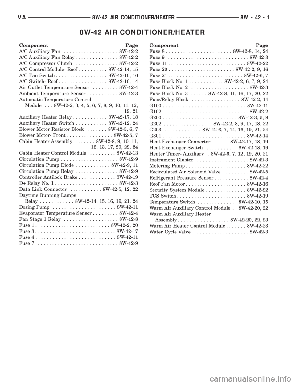
8W-42 AIR CONDITIONER/HEATER
Component Page
A/C Auxiliary Fan................... 8W-42-2
A/C Auxiliary Fan Relay............... 8W-42-2
A/C Compressor Clutch............... 8W-42-2
A/C Control Module- Roof.......... 8W-42-14, 15
A/C Fan Switch.................. 8W-42-10, 16
A/C Switch- Roof................. 8W-42-10, 14
Air Outlet Temperature Sensor......... 8W-42-4
Ambient Temperature Sensor........... 8W-42-3
Automatic Temperature Control
Module . . . 8W-42-2, 3, 4, 5, 6, 7, 8, 9, 10, 11, 12,
19, 21
Auxiliary Heater Relay............ 8W-42-17, 18
Auxiliary Heater Switch........... 8W-42-12, 24
Blower Motor Resistor Block....... 8W-42-5, 6, 7
Blower Motor- Front................ 8W-42-5, 7
Cabin Heater Assembly....... 8W-42-8, 9, 10, 11,
12, 13, 17, 20, 22, 24
Cabin Heater Control Module.......... 8W-42-13
Circulation Pump.................... 8W-42-9
Circulation Pump Diode............ 8W-42-9, 11
Circulation Pump Relay............... 8W-42-9
Controller Antilock Brake............. 8W-42-19
D+ Relay No. 1...................... 8W-42-3
Data Link Connector........... 8W-42-5, 12, 22
Daytime Running Lamps
Relay............ 8W-42-14, 15, 16, 19, 21, 24
Dosing Pump...................... 8W-42-11
Evaporator Temperature Sensor......... 8W-42-4
Fan Stage 1 Relay................... 8W-42-8
Fuse 1.......................... 8W-42-2, 20
Fuse 3............................ 8W-42-17
Fuse 4............................ 8W-42-11
Fuse 7............................ 8W-42-9Component Page
Fuse 8....................... 8W-42-8, 14, 24
Fuse 9............................ 8W-42-3
Fuse 11........................... 8W-42-22
Fuse 20....................... 8W-42-2, 9, 16
Fuse 21.......................... 8W-42-6, 7
Fuse Block No. 1............ 8W-42-2, 6, 7, 9, 24
Fuse Block No. 2.................... 8W-42-3
Fuse Block No. 3...... 8W-42-8, 11, 16, 17, 20, 22
Fuse/Relay Block................. 8W-42-2, 14
G100............................. 8W-42-11
G102.............................. 8W-42-2
G200.......................... 8W-42-3, 5, 9
G202................. 8W-42-2, 8, 9, 17, 18, 22
G203............. 8W-42-6, 7, 14, 16, 19, 21, 24
G301............................. 8W-42-14
Heat Exchanger Connector...... 8W-42-17, 18, 19
Heat Exchanger Switch........... 8W-42-18, 19
Heater Timer- Auxiliary . 8W-42-6, 7, 12, 19, 20, 21
Instrument Cluster................... 8W-42-3
Metering Pump..................... 8W-42-22
Recirculated Air Solenoid Valve......... 8W-42-5
Refrigerant Pressure Sensor............ 8W-42-4
Roof Fan Motor..................... 8W-42-16
Security System Module.............. 8W-42-22
TCS Switch........................ 8W-42-19
Temperature Switch.............. 8W-42-10, 15
Warm Air Auxiliary Control Module . . 8W-42-20, 22
Warm Air Auxiliary Heater
Assembly.................. 8W-42-20, 22, 23
Warm Air Heater Control Module....... 8W-42-23
Water Cycle Valve................... 8W-42-3
VA8W-42 AIR CONDITIONER/HEATER 8W - 42 - 1
Page 734 of 1232
OPERATION
The cigar lighter consists of two major components:
a knob and heating element unit, and the cigar
lighter base or receptacle shell. The receptacle shell
is connected to ground, and an insulated contact in
the bottom of the shell is connected to battery cur-
rent. The cigar lighter receives battery voltage from a
fuse in the fuseblock only when the ignition switch is
in the Accessory or On positions.
The knob and heating element are encased within
a spring-loaded housing, which also features a sliding
protective heat shield. When the heating element is
inserted in the receptacle shell, the heating element
resistor coil is grounded through its housing to the
receptacle shell. If the cigar lighter knob is pushed
inward, the heat shield slides up toward the knob
exposing the heating element.
Two small spring-clip retainers are located on
either side of the insulated contact inside the bottom
of the receptacle shell. These clips engage and hold
the heating element against the insulated contact
long enough for the resistor coil to heat up and glow.
When the resistor coil becomes sufficiently heated,
excess heat radiates from the heating element caus-
ing the spring-clips to expand. Once the spring-clips
expand far enough to release the heating element,
the spring-loaded housing forces the knob and heat-
ing element to pop back outward to their relaxed
position. When the cigar lighter knob and element
are pulled out of the receptacle shell, the protective
heat shield slides downward on the housing so that
the heating element is recessed and shielded around
its circumference for safety.
DIAGNOSIS AND TESTING - CIGAR LIGHTER
OUTLET
For cigar lighter outlet diagnosis and testing pro-
cedures (Refer to 8 - ELECTRICAL/POWER DISTRI-
BUTION/POWER OUTLET - DIAGNOSIS AND
TESTING)
REMOVAL
For cigar lighter outlet removal procedure (Refer to
8 - ELECTRICAL/POWER DISTRIBUTION/POWER
OUTLET - REMOVAL).
CIRCUIT BREAKER
DESCRIPTION
Automatic resetting circuit breakers are used to
protect the power window voltage supply circuits.
These circuit breakers can protect the systems from a
short circuit, or from an overload condition caused by
an obstructed or stuck power window regulator or
switch.The circuit breaker cannot be repaired and, if
faulty or damaged, it must be replaced.
OPERATION
The circuit breaker contains a bi-metal strip sand-
wiched between two contacts forming the connection
in the circuit. An overload condition causes the
bi-metal strip to heat and bend to the open position,
disconnecting current flow to the circuit. Then as the
system overload or short circuit is removed, the
bi-metal strip cools, re-establishing contact to allow
current flow to the circuit.
DIAGNOSIS AND TESTING - CIRCUIT BREAKER
For complete circuit descriptions and diagrams,
refer toWiring.
(1) Locate the correct circuit breaker in the fuse-
block. Pull out the circuit breaker slightly, but be cer-
tain that the circuit breaker terminals still contact
the terminals in the fuseblock cavities.
(2) Connect the negative lead of a 12-volt DC volt-
meter to a good ground.
(3) With the voltmeter positive lead, check both
terminals of the circuit breaker for battery voltage.
If only one terminal has battery voltage, the circuit
breaker is faulty and must be replaced. If neither ter-
minal has battery voltage, repair the open circuit
from the Power Distribution Center as required.
FUSE BLOCK #1
DESCRIPTION
An electrical fuse block is concealed under the
driver side steering column. The fuse block serves to
distribute electrical current to many of the electrical
systems in the vehicle. The fuse block contains blade-
type mini fuses, relays and micro processors that
enable automatic control of some of the power distri-
bution circuits throughout the vehicle.
The molded plastic fuse block housing has an inte-
gral mounting bracket that is secured with screws to
the steering column. A finger recess is molded into
the cover for easy removal. A fuse layout map is
molded onto the back side of the cover to ensure
proper fuse identification.
The fuse block cannot be repaired, if the fuse block
is faulty or damaged or if any internal circuit is
faulty or damaged, the entire fuse block must be
replaced.
OPERATION
All of the circuits entering and leaving the fuse
block do so through the instrument panel wire har-
ness. Internal connection of all of the fuse block cir-
cuits is accomplished by an intricate combination of
8W - 97 - 2 8W-97 POWER DISTRIBUTIONVA
CIGAR LIGHTER OUTLET (Continued)
Page 742 of 1232
CYLINDER LEAK DOWN VALUES
CYLINDER LEAK DOWN
PERMISSIBLE TOTAL
LOSS 25%
CYLINDER LEAK DOWN
PERMISSIBLE LOSS AT
VALVES AND CYLINDER
HEAD 10%
CYLINDER LEAK DOWN
PERMISSIBLE LOSS AT
PISTON AND RINGS 20%
STANDARD PROCEDURE - DETERMINING
CYLINDER PRESSURE LOSS
If an increased pressure loss was found with the
cylinder leak test, inspect the engine by listening at
the cylinder head gasket, air intake area, exhaust, oil
fill opening and where injectors and glow plugs enter
the cylinder head. Also check the engine coolant in
the radiator or expansion reservoir for the formation
of bubbles.
Possible causes for the pressure loss are:
POSSIBLE CAUSE FOR PRESSURE LOSS
CONDITION POSSIBLE
CAUSESCORRECTION
AIR LOSS
THROUGH
GLOW PLUG,
INJECTOR,
ADJACENT
CYLINDERS,
OR AIR
BUBBLES IN
COOLANT1. Sealing
SurfacesRepair Sealing
Surfaces
2. Gaskets 2. Replace
Component or
Gasket
3. Cylinder
Head Gasket3. Replace
Cylinder Head
Gasket
AIR LOSS
THROUGH AIR
INTAKE AREA1. Sealing
Surfaces1. Remove
Cylinder Head
for Further
Inspection
2. Intake Valves
and Seats2. Replace
Valves, Guides
or Seats
CONDITION POSSIBLE
CAUSESCORRECTION
AIR LOSS
THROUGH
EXHAUSTSealing
SurfacesRemove
Cylinder Head
for Further
Inspection
2. Exhaust
Valves and
Seats2. Replace
Valves, Guides
or Seats
AIR LOSS
THROUGH OIL
FILL OPENING1. Sealing
SurfacesRemove Engine
for Further
Inspection
2. Pistons,
Piston Rings2. Replace
Pistons or
Piston Rings
It is possible to pin point the pressure loss of the
relevant cylinder by spraying with clean engine oil.
Engine oil seals off the gap between the piston and
cylinder wall briefly. If a reduced pressure loss now
occurs for a short time, the cause is very likely to be
the pistons, piston rings or cylinder contact surfaces
of the relevant cylinder.
Determining the cause can be falsified by the posi-
tion of the piston ring joints. If suspicion exists that
the loss of pressure is caused by the piston ring
joints being positioned directly one above the other,
fit the parts to the engine and repeat this test after
running the engine for a short time.
REMOVAL
REMOVAL - ENGINE COVER
(1) Remove the retaining screws and remove cover
(Fig. 2).
REMOVAL
WARNING: RISK OF INJURY TO SKIN AND EYES
FROM SCALDING WITH HOT COOLANT. RISK OF
POISONING FROM SWALLOWING COOLANT. DO
NOT OPEN COOLING SYSTEM UNLESS COOLANT
TEMPERATURE IS BELOW 90ÉC (194ÉF). OPEN CAP
SLOWLY TO RELEASE PRESSURE. STORE COOL-
ANT IN SUITABLE AND APPROPRIATELY MARKED
CONTAINER. WEAR PROTECTIVE GLOVES,
CLOTHES, AND EYE WEAR.
CAUTION: STORE OR DISCARD ALL FLUIDS IN
SUITABLE AND APPROPRIATELY MARKED CON-
TAINERS.
(1) Disconnect the negative battery cable.
9 - 4 ENGINEVA
ENGINE (Continued)
Page 743 of 1232
(2) Remove the hood.
(3) Drain cooling system (Refer to 7 - COOLING/
ENGINE/COOLANT - STANDARD PROCEDURE).
(4) Evacuate and recover air conditioning system
(Refer to 24 - HEATING & AIR CONDITIONING/
PLUMBING - STANDARD PROCEDURE).
(5) Disconnect the engine wiring harness at the
vehicle side and carefully guide though the cowl into
the engine area.
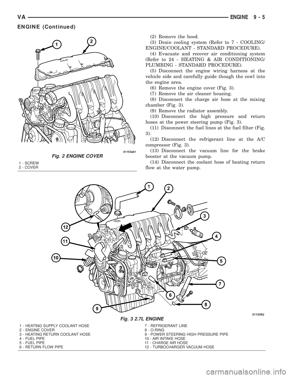
(6) Remove the engine cover (Fig. 3).
(7) Remove the air cleaner housing.
(8) Disconnect the charge air hose at the mixing
chamber (Fig. 3).
(9) Remove the radiator assembly.
(10) Disconnect the high pressure and return
hoses at the power steering pump (Fig. 3).
(11) Disconnect the fuel lines at the fuel filter (Fig.
3).
(12) Disconnect the refrigerant line at the A/C
compressor (Fig. 3).
(13) Disconnect the vacuum line for the brake
booster at the vacuum pump.
(14) Disconnect the coolant hose of heating return
flow at the water pump.
Fig. 3 2.7L ENGINE
1 - HEATING SUPPLY COOLANT HOSE 7 - REFRIGERANT LINE
2 - ENGINE COVER 8 - O-RING
3 - HEATING RETURN COOLANT HOSE 9 - POWER STEERING HIGH PRESSURE PIPE
4 - FUEL PIPE 10 - AIR INTAKE HOSE
5 - FUEL PIPE 11 - CHARGE AIR HOSE
6 - RETURN FLOW PIPE 12 - TURBOCHARGER VACUUM HOSE
Fig. 2 ENGINE COVER
1 - SCREW
2 - COVER
VAENGINE 9 - 5
ENGINE (Continued)
Page 746 of 1232
(11) Install the transmission cooler lines to trans-
mission.(Refer to 21 - TRANSMISSION/TRANS-
AXLE/AUTOMATIC - NAG1 - INSTALLATION) for
correct sequence and torque specification.
(12) Install transmission electrical connector and
shifter hardware.Refer to (Refer to 21 - TRANSMIS-
SION/TRANSAXLE/AUTOMATIC - NAG1 - INSTAL-
LATION) for correct sequence and torque
specification.
(13) Install the steering gear and tighten in two
stages. 25 N´m (18.5 lbs. ft.), then 45 N´m (33 lbs. ft.)
plus 90É.
(14) Install the crank sensor.
(15) Install the starter.
(16) Connect the ground strap (left side).
(17) Align and install the exhaust and bracket
(Refer to 11 - EXHAUST SYSTEM/EXHAUST PIPE -
INSTALLATION).
(18) Lower the vehicle.
(19) Install the air inlet hose at the turbocharger
(Fig. 3).
(20) Connect the vacuum hose at the turbocharger
(Fig. 3).
(21) Connect the coolant supply and return hoses
(Fig. 3).(22) Connect the brake booster vacuum hose at the
vacuum pump (Fig. 3).
(23) Connect the refrigerant lines (Fig. 3).
(24) Connect the fuel lines at the filter assembly
(Fig. 3).
(25) Connect the power steering hoses (Fig. 3).
(26) Install the radiator/charge air cooler and
hose(s) assemblies (Refer to 7 - COOLING/ENGINE/
RADIATOR - INSTALLATION).
(27) Install A/C condenser.
(28) Install air cleaner housing, sensors, and hoses
(Refer to 9 - ENGINE/AIR INTAKE SYSTEM/AIR
CLEANER HOUSING - INSTALLATION).
(29) Route the engine wiring harness inside the
vehicle and connect.
(30) Install the front grill assembly.
(31) Install and align the hood.
(32) Connect the negative battery cable.
(33) Check and fill engine oil.
(34) Fill cooling system to proper level with the
appropriate coolant.
(35) Evacuate and recharge air conditioning.
(36) Check and refill all ancillary system fluid lev-
els.
(37) Start engine and inspect for leaks.
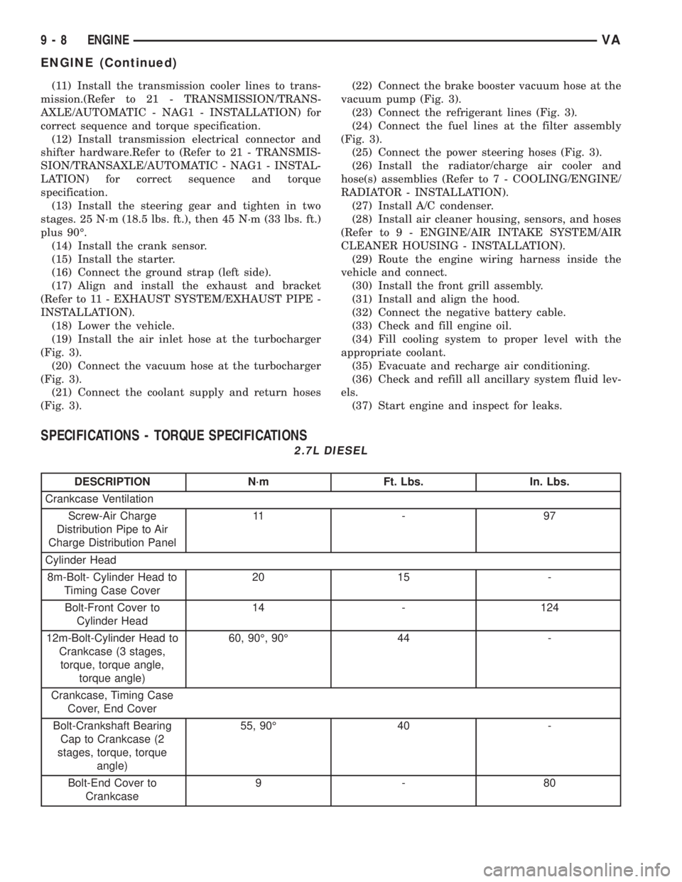
SPECIFICATIONS - TORQUE SPECIFICATIONS
2.7L DIESEL
DESCRIPTION N´m Ft. Lbs. In. Lbs.
Crankcase Ventilation
Screw-Air Charge
Distribution Pipe to Air
Charge Distribution Panel11 - 9 7
Cylinder Head
8m-Bolt- Cylinder Head to
Timing Case Cover20 15 -
Bolt-Front Cover to
Cylinder Head14 - 124
12m-Bolt-Cylinder Head to
Crankcase (3 stages,
torque, torque angle,
torque angle)60, 90É, 90É 44 -
Crankcase, Timing Case
Cover, End Cover
Bolt-Crankshaft Bearing
Cap to Crankcase (2
stages, torque, torque
angle)55, 90É 40 -
Bolt-End Cover to
Crankcase9-80
9 - 8 ENGINEVA
ENGINE (Continued)
Page 786 of 1232
NOTE: If grooves can be felt in the belt pulley/vibra-
tion damper during inspection, the pulley/damper
must be replaced.
(6) Inspect hub at belt pulley/vibration damper for
wear grooves.
(7) Replace front crankshaft seal.
INSTALLATION
NOTE: Align parallel key, fix in place with grease.
Turn to ensure the slot is aligned with parallel key
in crankshaft.
NOTE: Front crankshaft seal must be replaced
before installing the belt pulley/vibration damper.
(1) Position the belt pulley/vibration damper.
(2) Install crankshaft center bolt and washer.
Tighten bolt in two stages. M8.8 bolt to 200N´m (148
lbs. ft.) then 90É, M10.9 bolt to 325N´m (240 lbs. ft.)
then 90É.
(3) Remove the retaining lock for the crankshaft/
ring gear (Fig. 43).
NOTE: Inspect accessory drive belt for wear.
Replace as necessary.
(4) Install accessory drive belt (Refer to 7 - COOL-
ING/ACCESSORY DRIVE/DRIVE BELTS - INSTAL-
LATION).
(5) Reconnect negative battery cable.
WARNING: USE EXTREME CAUTION WHEN THE
ENGINE IS IN OPERATION. DO NOT STAND IN A
DIRECT LINE WITH THE FAN. DO NOT PUT YOUR
HANDS NEAR THE PULLEYS, BELTS OR FAN. DO
NOT WEAR LOOSE CLOTHING.
(6) Start vehicle and inspect for leaks.
VACUUM PUMP
DESCRIPTION
The vacuum pump is operated by a slotted exten-
sion attached to the vacuum pump shaft. The vac-
uum pump shaft slotted extension fits into, and is
driven by, the exhaust camshaft gear.
The vacuum pump is a constant displacement,
vane-type pump. Vacuum is generated by vanes
mounted in the pump rotor. The rotor is located in
the pump housing and is pressed onto the pump
shaft.
The vacuum pump rotating components are inter-
nally lubricated.The vacuum pump is not serviceable and must be
replaced as a unit. Do not disassemble or attempt to
repair the pump.
OPERATION
Vacuum pump output is transmitted to the Heater,
Electronic, Vacuum, Air Conditioner (HEVAC) and
speed control, systems through a supply hose. The
hose is connected to an outlet port on the pump hous-
ing and uses an in-line check valve to retain system
vacuum when vehicle is not running.
Pump output ranges from a minimum of 8.5 to 25
inches vacuum.
The pump rotor and vanes are rotated by the pump
drive gear. The drive gear is operated by the exhaust
camshaft gear.
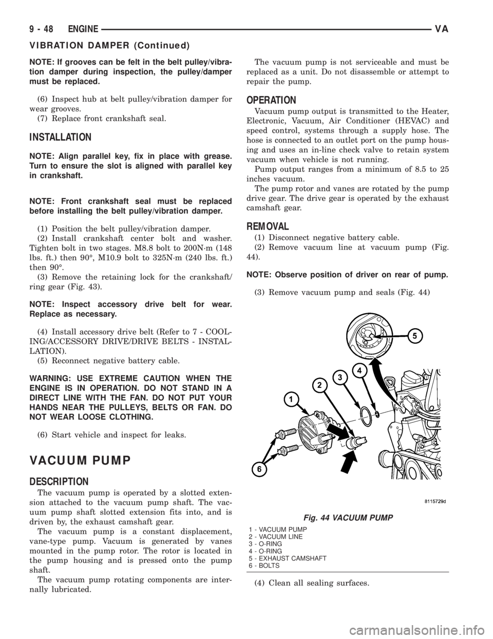
REMOVAL
(1) Disconnect negative battery cable.
(2) Remove vacuum line at vacuum pump (Fig.
44).
NOTE: Observe position of driver on rear of pump.
(3) Remove vacuum pump and seals (Fig. 44)
(4) Clean all sealing surfaces.
Fig. 44 VACUUM PUMP
1 - VACUUM PUMP
2 - VACUUM LINE
3 - O-RING
4 - O-RING
5 - EXHAUST CAMSHAFT
6 - BOLTS
9 - 48 ENGINEVA
VIBRATION DAMPER (Continued)
Page 798 of 1232
(6) Remove the oil filter to allow the oil to flow off
into the oil pan.
(7) Remove the radiator assembly (Refer to 7 -
COOLING/ENGINE/RADIATOR - REMOVAL).
(8) Remove engine cover (Refer to 9 - ENGINE -
REMOVAL).
(9) Remove front cover at cylinder head (Refer to 9
- ENGINE/CYLINDER HEAD - REMOVAL).
(10) Remove accessory drive belt.
(11) Remove the high pressure fuel pump (Refer to
14 - FUEL SYSTEM/FUEL DELIVERY/FUEL PUMP
- REMOVAL).
(12) Remove water pump (Refer to 7 - COOLING/
ENGINE/WATER PUMP - REMOVAL).
(13) Remove accessory drive belt pulley and vibra-
tion damper (Refer to 9 - ENGINE/ENGINE BLOCK/
VIBRATION DAMPER - REMOVAL).
(14) Remove the power steering pump.
NOTE: NO NOT open the air conditioning system.
(15) Unplug AC compressor electrical connector
and unbolt AC compressor. Relocate in lower engine
compartmentwith outopening the system.
(16) Remove the generator with wiring attached
and relocate somewhere in the engine compartment.
(17) Install engine support fixture.
(18) Remove the oil pan.
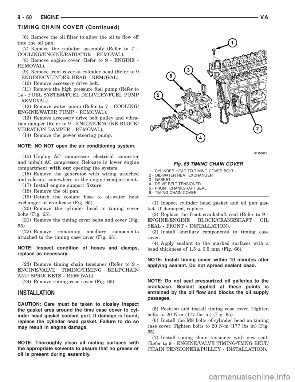
(19) Detach the coolant hose to oil-water heat
exchanger at crankcase (Fig. 65).
(20) Remove the cylinder head to timing cover
bolts (Fig. 65).
(21) Remove the timing cover bolts and cover (Fig.
65).
(22) Remove remaining ancillary components
attached to the timing case cover (Fig. 65).
NOTE: Inspect condition of hoses and clamps,
replace as necessary.
(23) Remove timing chain tensioner (Refer to 9 -
ENGINE/VALVE TIMING/TIMING BELT/CHAIN
AND SPROCKETS - REMOVAL)
(24) Remove timing case cover (Fig. 65).
INSTALLATION
CAUTION: Care must be taken to closley inspect
the gasket area around the time case cover to cyl-
inder head gasket coolant port. If damage is found,
replace the cylinder head gasket. Failure to do so
may result in engine damage.
NOTE: Thoroughly clean all mating surfaces with
the appropriate solvents to assure that no grease or
oil is present during assembly.(1) Inspect cylinder head gasket and oil pan gas-
ket. If damaged, replace.
(2) Replace the front crankshaft seal (Refer to 9 -
ENGINE/ENGINE BLOCK/CRANKSHAFT OIL
SEAL - FRONT - INSTALLATION).
(3) Install ancillary components to timing case
cover.
(4) Apply sealant to the marked surfaces with a
bead thickness of 1.5 0.5 mm (Fig. 66).
NOTE: Install timing cover within 10 minutes after
applying sealant. Do not spread sealant bead.
NOTE: Do not seal pressurized oil galleries to the
crankcase. Sealant applied at these points is
entrained by the oil flow and blocks the oil supply
passages.
(5) Position and install timing case cover. Tighten
bolts to 20 N´m (177 lbs in) (Fig. 65).
(6) Install the M8 bolts of cylinder head on timing
case cover. Tighten bolts to 20 N´m (177 lbs in) (Fig.
65).
(7) Install timing chain tensioner with new seal-
(Refer to 9 - ENGINE/VALVE TIMING/TMNG BELT/
CHAIN TENSIONER&PULLEY - INSTALLATION).
Fig. 65 TIMING CHAIN COVER
1 - CYLINDER HEAD TO TIMING COVER BOLT
2 - OIL-WATER HEAT EXCHANGER
3 - GASKET
4 - DRIVE BELT TENSIONER
5 - FRONT CRANKSHAFT SEAL
6 - TIMING CHAIN COVER
9 - 60 ENGINEVA
TIMING CHAIN COVER (Continued)
Page 799 of 1232
(8) Position and install the oil pan. Tighten M6
bolts to 9 N´m (80 lbs in) and M8 bolts to 20 N´m
(177 lbs in).
(9) Install belt /pulley vibration damper. Tighten
M8.8 bolt in two stages, 200N´m (147 lbs ft.) then
90É, M10.9 bolt 325N´m (240 lbs ft) then 90É.
(10) Remove the engine support fixture.
(11) Install generator (Refer to 8 - ELECTRICAL/
CHARGING/GENERATOR - INSTALLATION).
(12) Install the air conditioning compressor.
(13) Install the power steering pump.
(14) Install water pump (Refer to 7 - COOLING/
ENGINE/WATER PUMP - INSTALLATION).
(15) Connect coolant hose to oil-water heat
exchanger.
(16) Install high pressure fuel pump (Refer to 14 -
FUEL SYSTEM/FUEL DELIVERY/FUEL PUMP -
INSTALLATION).
(17) Apply sealant to lower portion of, and install,
front cover to cylinder block. Tighten bolts to 20N´m
(177 lbs in) (Refer to 9 - ENGINE/CYLINDER HEAD
- INSTALLATION).
(18) Remove retaining lock for crankshaft/starter
ring gear.
(19) Tighten the oil drain plug to 30N´m (265 lbs
in).
(20) Install a new oil filter. tighten screw cap for
filter to 25N´m (221 lbs. in.).
(21) Install the accessory drive belt.
(22) Install the radiator assembly (Refer to 7 -
COOLING/ENGINE/RADIATOR - INSTALLATION).(23) Install air intake hose.
(24) Fill coolant to the proper level, with the
proper coolant (Refer to 7 - COOLING/ENGINE/
COOLANT - STANDARD PROCEDURE).
(25) Fill the crankcase with the correct oil, to the
proper level. Refer to owners manual for specifica-
tions.
(26) Connect the negative battery cable.
WARNING: USE EXTREME CAUTION WHEN THE
ENGINE IS OPERATING. DO NOT STAND IN A
DIRECT LINE WITH THE FAN. DO NOT PUT YOUR
HANDS NEAR THE PULLEYS, BELTS OR FAN. DO
NOT WEAR LOOSE CLOTHES.
CAUTION: DO NOT pressure test cooling system
until the engine reaches operating temperature.
(27) Start engine and inspect for leaks. care must
be taken to observe the fuel system warning (Refer to
14 - FUEL SYSTEM - WARNING).
TIMING BELT/CHAIN AND
SPROCKETS
REMOVAL
REMOVAL - TENSIONING AND SLIDE RAILS
NOTE: If it necessary to replace the tensioning rail,
slide rail or tensioning arm, they are always
replaced together.
(1) Disconnect negative battery cable.
(2) Remove the engine (Refer to 9 - ENGINE -
REMOVAL).
(3) Remove cylinder head (Refer to 9 - ENGINE/
CYLINDER HEAD - REMOVAL).
NOTE: Remove timing case cover carefully. Care
must be taken not to damage oil pan gasket.
(4) Remove timing case cover (Refer to 9 -
ENGINE/VALVE TIMING/TIMING BELT / CHAIN
COVER(S) - REMOVAL).
(5) Pull the tensioning rail off of the bearing pins
(Fig. 67).
(6) Release the spring at the slide rail and take it
off of the tensioning arm (Fig. 67).
REMOVAL - INTERMEDIATE GEAR
(1) Disconnect negative battery cable.
(2) Remove engine cover (Refer to 9 - ENGINE -
REMOVAL).
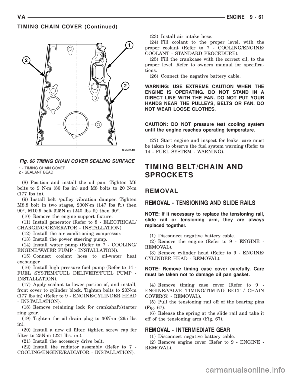
Fig. 66 TIMING CHAIN COVER SEALING SURFACE
1 - TIMING CHAIN COVER
2 - SEALANT BEAD
VAENGINE 9 - 61
TIMING CHAIN COVER (Continued)