2005 MERCEDES-BENZ SPRINTER air condition
[x] Cancel search: air conditionPage 153 of 1232
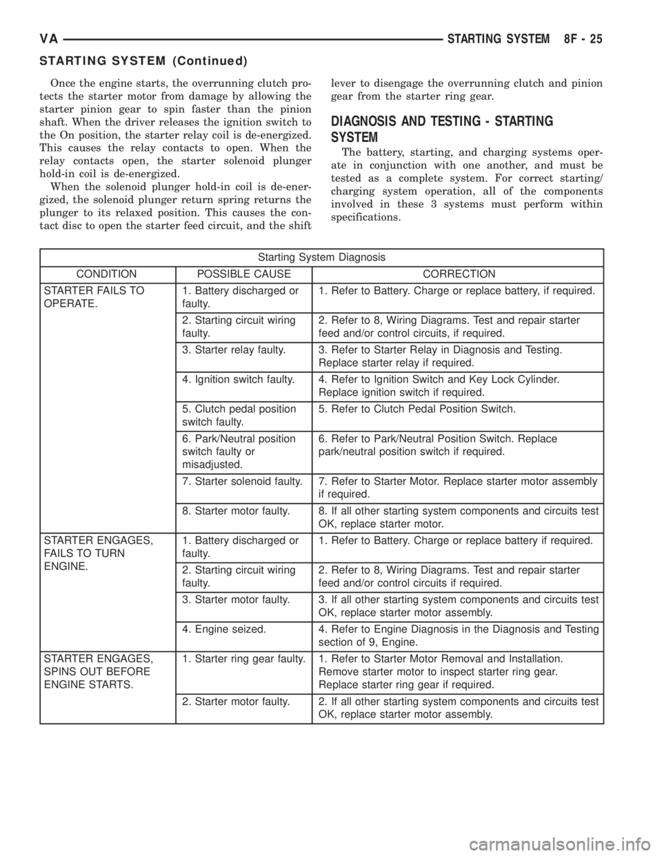
Once the engine starts, the overrunning clutch pro-
tects the starter motor from damage by allowing the
starter pinion gear to spin faster than the pinion
shaft. When the driver releases the ignition switch to
the On position, the starter relay coil is de-energized.
This causes the relay contacts to open. When the
relay contacts open, the starter solenoid plunger
hold-in coil is de-energized.
When the solenoid plunger hold-in coil is de-ener-
gized, the solenoid plunger return spring returns the
plunger to its relaxed position. This causes the con-
tact disc to open the starter feed circuit, and the shiftlever to disengage the overrunning clutch and pinion
gear from the starter ring gear.
DIAGNOSIS AND TESTING - STARTING
SYSTEM
The battery, starting, and charging systems oper-
ate in conjunction with one another, and must be
tested as a complete system. For correct starting/
charging system operation, all of the components
involved in these 3 systems must perform within
specifications.
Starting System Diagnosis
CONDITION POSSIBLE CAUSE CORRECTION
STARTER FAILS TO
OPERATE.1. Battery discharged or
faulty.1. Refer to Battery. Charge or replace battery, if required.
2. Starting circuit wiring
faulty.2. Refer to 8, Wiring Diagrams. Test and repair starter
feed and/or control circuits, if required.
3. Starter relay faulty. 3. Refer to Starter Relay in Diagnosis and Testing.
Replace starter relay if required.
4. Ignition switch faulty. 4. Refer to Ignition Switch and Key Lock Cylinder.
Replace ignition switch if required.
5. Clutch pedal position
switch faulty.5. Refer to Clutch Pedal Position Switch.
6. Park/Neutral position
switch faulty or
misadjusted.6. Refer to Park/Neutral Position Switch. Replace
park/neutral position switch if required.
7. Starter solenoid faulty. 7. Refer to Starter Motor. Replace starter motor assembly
if required.
8. Starter motor faulty. 8. If all other starting system components and circuits test
OK, replace starter motor.
STARTER ENGAGES,
FAILS TO TURN
ENGINE.1. Battery discharged or
faulty.1. Refer to Battery. Charge or replace battery if required.
2. Starting circuit wiring
faulty.2. Refer to 8, Wiring Diagrams. Test and repair starter
feed and/or control circuits if required.
3. Starter motor faulty. 3. If all other starting system components and circuits test
OK, replace starter motor assembly.
4. Engine seized. 4. Refer to Engine Diagnosis in the Diagnosis and Testing
section of 9, Engine.
STARTER ENGAGES,
SPINS OUT BEFORE
ENGINE STARTS.1. Starter ring gear faulty. 1. Refer to Starter Motor Removal and Installation.
Remove starter motor to inspect starter ring gear.
Replace starter ring gear if required.
2. Starter motor faulty. 2. If all other starting system components and circuits test
OK, replace starter motor assembly.
VASTARTING SYSTEM 8F - 25
STARTING SYSTEM (Continued)
Page 154 of 1232
Starting System Diagnosis
CONDITION POSSIBLE CAUSE CORRECTION
STARTER DOES NOT
DISENGAGE.1. Starter motor
improperly installed.1. Refer to Starter Motor Removal and Installation.
Tighten starter mounting hardware to correct torque
specifications.
2. Starter relay faulty. 2. Refer to Starter Relay Diagnosis and Testing. Replace
starter relay if required.
3. Ignition switch faulty. 3. Refer to Ignition Switch and Key Lock Cylinder.
Replace ignition switch if required.
4. Starter motor faulty. 4. If all other starting system components and circuits test
OK, replace starter motor.
INSPECTION
For complete starter wiring circuit diagrams, refer
to 8, Wiring Diagrams. Before removing any unit
from starting system for repair or diagnosis, perform
the following inspections:
WARNING: ON VEHICLES EQUIPPED WITH AIR-
BAGS, REFER TO 8, PASSIVE RESTRAINT SYS-
TEMS, BEFORE ATTEMPTING ANY STEERING
WHEEL, STEERING COLUMN, OR INSTRUMENT
PANEL COMPONENT DIAGNOSIS OR SERVICE.
FAILURE TO TAKE THE PROPER PRECAUTIONS
COULD RESULT IN ACCIDENTAL AIRBAG DEPLOY-
MENT AND POSSIBLE PERSONAL INJURY.
²Battery- Visually inspect battery for indica-
tions of physical damage and loose or corroded cable
connections. Determine state-of-charge and cranking
capacity of battery. Charge or replace battery if
required. Refer toBatteryin 8, Battery.
²Ignition Switch- Visually inspect ignition
switch for indications of physical damage and loose
or corroded wire harness connections. Refer toIgni-
tion Switch and Key Lock Cylinder.
²Park/Neutral Position Switch- Visually
inspect park/neutral position switch for indications of
physical damage and loose or corroded wire harness
connections. Refer toPark/Neutral Position
Switchin 21, Transmission.
²Starter Relay- Visually inspect starter relay
for indications of physical damage and loose or cor-
roded wire harness connections.
²Starter Motor- Visually inspect starter motor
for indications of physical damage and loose or cor-
roded wire harness connections.
²Starter Solenoid- Visually inspect starter sole-
noid for indications of physical damage and loose or
corroded wire harness connections.
²Wiring- Visually inspect wire harnesses for
damage or corrosion. Repair or replace any faulty
wiring, as required. Refer to 8, Wiring Diagrams.
TESTING
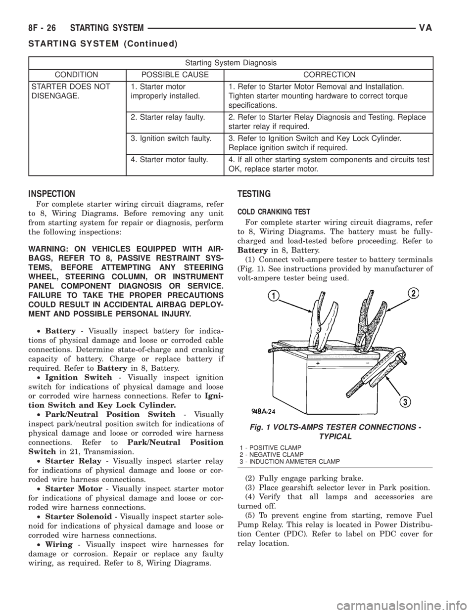
COLD CRANKING TEST
For complete starter wiring circuit diagrams, refer
to 8, Wiring Diagrams. The battery must be fully-
charged and load-tested before proceeding. Refer to
Batteryin 8, Battery.
(1) Connect volt-ampere tester to battery terminals
(Fig. 1). See instructions provided by manufacturer of
volt-ampere tester being used.
(2) Fully engage parking brake.
(3) Place gearshift selector lever in Park position.
(4) Verify that all lamps and accessories are
turned off.
(5) To prevent engine from starting, remove Fuel
Pump Relay. This relay is located in Power Distribu-
tion Center (PDC). Refer to label on PDC cover for
relay location.
Fig. 1 VOLTS-AMPS TESTER CONNECTIONS -
TYPICAL
1 - POSITIVE CLAMP
2 - NEGATIVE CLAMP
3 - INDUCTION AMMETER CLAMP
8F - 26 STARTING SYSTEMVA
STARTING SYSTEM (Continued)
Page 159 of 1232
INSTALLATION
(1) Raise and support vehicle.
(2) Position starter motor to transmission housing.
(3) Install 2 mounting bolts. Refer to Torque Spec-
ifications.
(4) Lower vehicle.
(5) Connect battery cable and solenoid wiring to
solenoid (2 nuts). Refer to Torque Specifications.
(6) Position wiring harness trough and install
retaining bolt.
(7) Install new nylon tie-wraps to wiring trough.
(8) Connect negative battery cable.
STARTER MOTOR RELAY
DESCRIPTION
The starter relay is an electromechanical device
that switches battery current to the pull-in coil of the
starter solenoid when ignition switch is turned to
Start position. The starter relay is located in the
Fuse/Relay Block. The Fuse/Relay Block is located
under, and to the left side of the drivers seat. See
Fuse/Relay Block cover for relay identification and
location.
The starter relay is an International Standards
Organization (ISO) relay. Relays conforming to ISO
specifications have common physical dimensions, cur-
rent capacities, terminal patterns, and terminal func-
tions.
The starter relay cannot be repaired or adjusted
and, if faulty or damaged, it must be replaced.
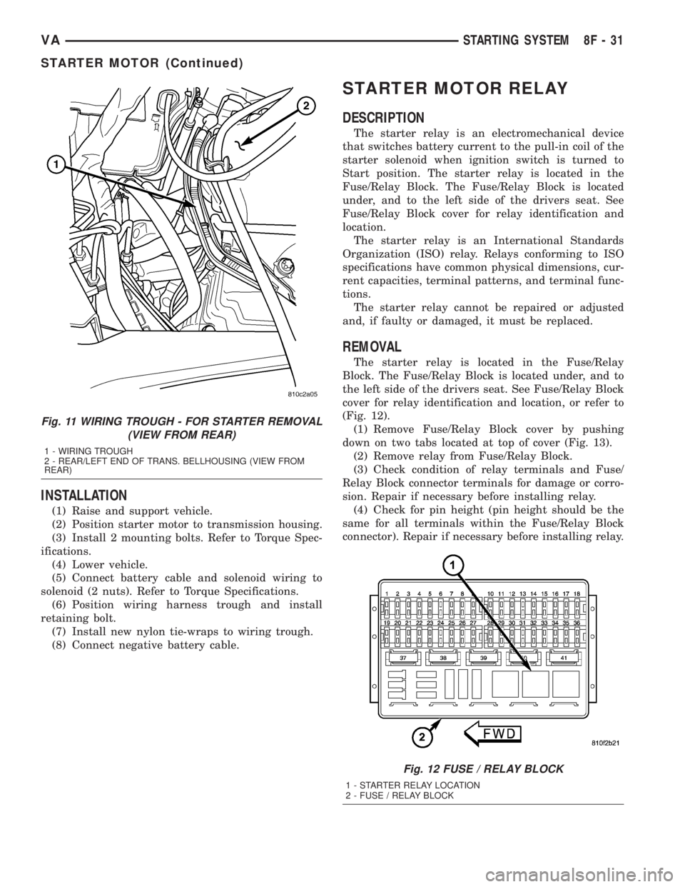
REMOVAL
The starter relay is located in the Fuse/Relay
Block. The Fuse/Relay Block is located under, and to
the left side of the drivers seat. See Fuse/Relay Block
cover for relay identification and location, or refer to
(Fig. 12).
(1) Remove Fuse/Relay Block cover by pushing
down on two tabs located at top of cover (Fig. 13).
(2) Remove relay from Fuse/Relay Block.
(3) Check condition of relay terminals and Fuse/
Relay Block connector terminals for damage or corro-
sion. Repair if necessary before installing relay.
(4) Check for pin height (pin height should be the
same for all terminals within the Fuse/Relay Block
connector). Repair if necessary before installing relay.
Fig. 11 WIRING TROUGH - FOR STARTER REMOVAL
(VIEW FROM REAR)
1 - WIRING TROUGH
2 - REAR/LEFT END OF TRANS. BELLHOUSING (VIEW FROM
REAR)
Fig. 12 FUSE / RELAY BLOCK
1 - STARTER RELAY LOCATION
2 - FUSE / RELAY BLOCK
VASTARTING SYSTEM 8F - 31
STARTER MOTOR (Continued)
Page 162 of 1232
OPERATION
The heated seat system is designed to provide indi-
vidually controlled, supplemental heat to the seat
cushion and seat back surfaces of both front seats.
Because this system converts electrical current to
heat, the heated seat system can provide a measure
of warm comfort almost immediately upon entering a
cold vehicle, rather than having to wait for the
engine coolant to reach sufficient temperature to
deliver heat through the conventional heater system.
This system allows each front seat occupant to indi-
vidually select one of two comfort levels, Hi or Lo, or
to turn the heater for their seat off.
The heated seat system components operate on
battery current received through a fuse in the Fuse
Block on a fused ignition switch output (run-acc) cir-
cuit so that the system will only operate when theignition switch is in the On or Accessory positions.
The heated seat system will be turned Off automati-
cally whenever the ignition switch is turned to any
position except On or Accessory. Also, the heated seat
system will not operate when the surface tempera-
ture of the seat cushion cover at either heated seat
sensor is above the designed temperature set points
of the system.
DIAGNOSIS AND TESTING - HEATED SEATS
Refer toWiringfor the appropriate wiring infor-
mation. The wiring information includes wiring dia-
grams, proper wire and connector repair procedures,
further details on wire harness routing and reten-
tion, as well as pin-out and location views for the
various wire harness connectors, splices and grounds.
HEATED SEAT SYSTEM DIAGNOSIS
CONDITION POSSIBLE CAUSES CORRECTION
NO HEATED SEAT SWITCH
ILLUMINATION WITH
IGNITION ON1. Faulty fuse. 1. Check heated seat fuse in Fuse Block.
Replace fuse, if required.
2. Wiring faulty. 2. Check fused ignition switch output (run-acc)
circuit from heated seat switch connector to
ignition switch. Repair, if required.
3. Ground faulty. 3. Check for ground at heated seat switch
connector. Repair, if required.
4. Faulty switch. 4. Refer to Heated Seat Switch for the proper
switch diagnosis and testing procedures.
DRIVER HEATED SEAT
SWITCH
DESCRIPTION
The heated seat switches are located on the instru-
ment panel, in the accessory switch bezel. The two,
momentary rocker type switches provide a signal to
the Heated Seat Relay through separate hard wired
circuits. Each switch contains two light emitting
diodes (LED), one for each High and Low setting to
let the occupant know that the seat heater system is
on.
The heated seat switches and their LED's cannot
be repaired. If either switch is faulty or damaged the
entire switch must be replaced.
OPERATION
There are three modes that can be selected with
each of the heated seat switches: Off, Low, and High.
When the top of the switch rocker is depressed, the
low mode is selected and the low mode LED indicator
illuminates. Depressing the top of the switch rocker asecond time will turn the heated seat to Off. This
same process is repeated for High heat setting. The
heated seats will automatically return to the Off
mode anytime the vehicle ignition switch is turned
Off.
Both switches provide separate hard wire inputs to
the Heated Seat Relay to indicate the selected mode.
The Heated Seat Relay responds to the heated seat
switch messages by controlling the output to the seat
heater elements of the selected seat.
DIAGNOSIS AND TESTING - DRIVER HEATED
SEAT SWITCH
For circuit description and diagrams, refer toWir-
ing.
(1) Inspect the Heated Seat Switches for apparent
damage or sticking/binding and replace if required.
Refer to Heated Seat Switch Removal and Installa-
tion in this section.
(2) Replace the heated seat switch with a known
good unit and retest the heated seat system.
8G - 2 HEATED SYSTEMSVA
HEATED SEATS (Continued)
Page 173 of 1232
arate take out and connector of the vehicle wire
harness.
Located between the rear cover and the cluster
hood is the cluster housing. The molded plastic clus-
ter housing serves as the carrier for the cluster elec-
tronic circuit board and circuitry, the cluster
connector receptacles, the gauges, a Light Emitting
Diode (LED) for each cluster indicator and general
illumination lamp, the multi-function indicator LCD
unit, electronic tone generators, the cluster overlay,
the gauge pointers, the multi-function indicator
switches and the four switch push buttons.
The cluster overlay is a laminated plastic unit. The
dark, visible, outer surface of the overlay is marked
with all of the gauge dial faces and graduations, but
this layer is also translucent. The darkness of this
outer layer prevents the cluster from appearing clut-
tered or busy by concealing the cluster indicators
that are not illuminated, while the translucence of
this layer allows those indicators and icons that are
illuminated to be readily visible. The underlying
layer of the overlay is opaque and allows light from
the LED for each of the various indicators and illu-
mination lamps behind it to be visible through the
outer layer of the overlay only through predeter-
mined cutouts. A rectangular opening in the overlay
at the base of the speedometer provides a window
through which the illuminated multi-function indica-
tor LCD unit can be viewed.
Several versions of the EMIC module are offered
on this model. These versions accommodate all of the
variations of optional equipment and regulatory
requirements for the various markets in which the
vehicle will be offered. The microprocessor-based
EMIC utilizes integrated circuitry, Electrically Eras-
able Programmable Read Only Memory (EEPROM)
type memory storage, information carried on the
Controller Area Network (CAN) data bus, along with
several hard wired analog and multiplexed inputs to
monitor systems, sensors and switches throughout
the vehicle.
In response to those inputs, the hardware and soft-
ware of the EMIC allow it to control and integrate
many electronic functions and features of the vehicle
through both hard wired outputs and the transmis-
sion of electronic message outputs to other electronic
modules in the vehicle over the CAN data bus. (Refer
to 8 - ELECTRICAL/ELECTRONIC CONTROL
MODULES/COMMUNICATION - DESCRIPTION -
CAN BUS).
Besides typical instrument cluster gauge and indi-
cator support, the electronic functions and features
that the EMIC supports or controls include the fol-
lowing:
²Active Service System- In vehicles equipped
with the Active Service SYSTem (ASSYST) engine oilmaintenance indicator option, the EMIC electronic
circuit board includes a second dedicated micropro-
cessor. This second microprocessor evaluates various
data including time, mileage, and driving conditions
to calculate the required engine oil service intervals,
and provides both visual and audible alerts to the
vehicle operator when certain engine oil maintenance
services are required.
²Audible Warnings- The EMIC electronic cir-
cuit board is equipped with an audible tone generator
and programming that allows it to provide various
audible alerts to the vehicle operator, including buzz-
ing and chime tones. An audible contactless elec-
tronic relay is also soldered onto the circuit board to
produce audible clicks that is synchronized with turn
signal indicator flashing to emulate the sounds of a
conventional turn signal or hazard warning flasher.
These audible clicks can occur at one of two rates to
emulate both normal and bulb-out turn or hazard
flasher operation. (Refer to 8 - ELECTRICAL/
CHIME/BUZZER - DESCRIPTION).
²Panel Lamps Dimming Control- The EMIC
provides a hard wired 12-volt Pulse-Width Modulated
(PWM) output that synchronizes the dimming level
of all panel lamps dimmer controlled lamps with that
of the cluster general illumination lamps and multi-
function indicator.
The EMIC houses four analog gauges and has pro-
visions for up to nineteen indicators (Fig. 3). The
EMIC includes the following analog gauges:
²Coolant Temperature Gauge
²Fuel Gauge
²Speedometer
²Tachometer
The EMIC includes provisions for the following
indicators (Fig. 3):
²Airbag (SRS) Indicator
²Antilock Brake System (ABS) Indicator
²Brake Indicator
²Brake Wear Indicator
²Charging Indicator
²Clogged Fuel Filter Indicator
²Coolant Low Indicator
²High Beam Indicator
²Low Fuel Indicator
²Malfunction Indicator Lamp (MIL)
²Multi-Function Indicator (LCD)
²Seatbelt Indicator
²Traction Control (ASR) Indicator
²Traction Control (ASR) Malfunction Indica-
tor
²Turn Signal (Right and Left) Indicators
²Washer Fluid Indicator
²Wait-To-Start Indicator
²Water-In-Fuel Indicator
VAINSTRUMENT CLUSTER 8J - 3
INSTRUMENT CLUSTER (Continued)
Page 175 of 1232
The EMIC modules for this model are serviced only
as complete units. The EMIC module cannot be
adjusted or repaired. If a gauge, an LED indicator,
the multi-fuction indicator LCD unit, an electronic
tone generator, the electronic circuit board, the cir-
cuit board hardware, the cluster overlay, the cluster
housing, the cluster hood, the cluster lens, or the
cluster rear cover are damaged or faulty, the entire
EMIC module must be replaced.
OPERATION
The ElectroMechanical Instrument Cluster (EMIC)
is designed to allow the vehicle operator to monitor
the conditions of many of the vehicle components and
operating systems. The gauges, meters and indicators
in the EMIC provide valuable information about the
powertrain, fuel and emissions systems, cooling sys-
tem, lighting systems, safety systems and many
other convenience items. The EMIC is installed in
the instrument panel so that all of these monitors
can be easily viewed by the vehicle operator when
driving, while still allowing relative ease of access for
service. The microprocessor-based EMIC hardware
and software uses various inputs to control the
gauges and indicators visible on the face of the clus-
ter. Some of these inputs are hard wired, but many
are in the form of electronic messages that are trans-
mitted by other electronic modules over the Control-
ler Area Network (CAN) data bus network. (Refer to
8 - ELECTRICAL/ELECTRONIC CONTROL MOD-
ULES/COMMUNICATION - OPERATION).
The EMIC microprocessor smooths the input data
using algorithms to provide gauge readings that are
accurate, stable and responsive to operating condi-
tions. These algorithms are designed to provide
gauge readings during normal operation that are con-
sistent with customer expectations. However, when
abnormal conditions exist such as high coolant tem-
perature, the algorithm can drive the gauge pointer
to an extreme position and the microprocessor can
sound a chime through the on-board audible tone
generator to provide distinct visual and audible indi-
cations of a problem to the vehicle operator. The
instrument cluster circuitry also provides audible
turn signal and hazard warning support by emulat-
ing the ªtickingº sound associated with a conven-
tional electro-mechanical flasher using a contactless
relay. The relay will also provide an indication of a
turn signal failure by sounding at double the usual
frequency. Each audible warning is provided to the
vehicle operator to supplement a visual indication.
The EMIC circuitry operates on battery current
received through a non-switched fused B(+) circuit,
and on a fused ignition switch output circuit. The
EMIC circuitry is grounded through a ground circuit
and take out of the frame wire harness with an eye-let terminal connector that is secured to a stud by a
nut at a ground location on the dash panel just for-
ward of the instrument cluster. Separate switched
ground inputs from the key-in ignition switch and
the front door jamb switches provide wake-up signals
to the EMIC circuitry. This arrangement allows the
EMIC to provide some features regardless of the igni-
tion switch position, while other features will operate
only with the ignition switch in the On position.
Proper diagnosis and testing of the EMIC, the
CAN data bus, the data bus electronic message
inputs to and outputs from the EMIC, as well as the
retrieval or erasure of a Diagnostic Trouble Code
(DTC) requires the use of a DRBIIItscan tool. Refer
to the appropriate diagnostic information. See the
owner's manual in the vehicle glove box for more
information on the features, use and operation of the
EMIC.
GAUGES
All gauges receive battery current through the
EMIC circuitry only when the instrument cluster
detects the ignition switch is in the On position. With
the ignition switch in the Off position, battery cur-
rent is not supplied to any gauges and the EMIC cir-
cuitry is programmed to move all of the gauge
needles back to the low end of their respective scales.
Therefore, the gauges do not accurately indicate any
vehicle condition unless the ignition switch is in the
On position.
All of the EMIC gauges are air core magnetic
units. Two fixed electromagnetic coils are located
within each gauge. These coils are wrapped at right
angles to each other around a movable permanent
magnet. The movable magnet is suspended within
the coils on one end of a pivot shaft, while the gauge
needle is attached to the other end of the shaft. One
of the coils has a fixed current flowing through it to
maintain a constant magnetic field strength. Current
flow through the second coil changes, which causes
changes in its magnetic field strength. The current
flowing through the second coil is changed by the
EMIC circuitry in response to messages received over
the CAN data bus. The gauge needle moves as the
movable permanent magnet aligns itself to the
changing magnetic fields created around it by the
electromagnets.
Proper diagnosis and testing of the gauges, the
CAN data bus and the electronic data bus message
inputs to the EMIC that control each gauge require
the use of a DRBIIItscan tool. Refer to the appro-
priate diagnostic information. Specific operation
details for each gauge may be found elsewhere in
this service information.
VAINSTRUMENT CLUSTER 8J - 5
INSTRUMENT CLUSTER (Continued)
Page 180 of 1232
²ABS Lamp-On Message- Each time the clus-
ter receives a lamp-on message from the CAB, the
ABS indicator will be illuminated. The indicator
remains illuminated until the cluster receives a
lamp-off message from the CAB, or until the ignition
switch is turned to the Off position, whichever occurs
first.
The CAB continually monitors the ABS and EBV
circuits and sensors to decide whether the systems
are in good operating condition. The CAB then sends
the proper lamp-on or lamp-off messages to the
instrument cluster. If the CAB sends a lamp-on mes-
sage after the bulb test, it indicates that the CAB
has detected a system malfunction and/or that the
ABS or EBV systems have become inoperative. The
CAB will store a Diagnostic Trouble Code (DTC) for
any malfunction it detects. For proper diagnosis of
the ABS and EBV systems, the CAB, the CAN data
bus, the electronic message inputs to the instrument
cluster, or the instrument cluster circuitry that con-
trols the ABS indicator, a DRBIIItscan tool is
required. Refer to the appropriate diagnostic infor-
mation.
AIRBAG INDICATOR
DESCRIPTION
An airbag indicator is standard equipment on all
instrument clusters. The airbag indicator is located
near the left edge of the instrument cluster, next to
the tachometer. The airbag indicator consists of a
stencil-like cutout of the letters ªSRSº in the opaque
layer of the instrument cluster overlay. The dark
outer layer of the overlay prevents the indicator from
being clearly visible when it is not illuminated. A red
Light Emitting Diode (LED) behind the cutout in the
opaque layer of the overlay causes the ªSRSº text to
appear in red through the translucent outer layer of
the overlay when the indicator is illuminated from
behind by the LED, which is soldered onto the
instrument cluster electronic circuit board. The air-
bag indicator is serviced as a unit with the instru-
ment cluster.
OPERATION
The airbag (SRS) indicator gives an indication to
the vehicle operator when the Airbag Control Module
(ACM) has recorded a Diagnostic Trouble Code (DTC)
for a Supplemental Restraint System (SRS) circuit or
component malfunction. Such a DTC may indicate
that the SRS is faulty or inoperative. The airbag
indicator is controlled by a transistor on the instru-
ment cluster circuit board based upon cluster pro-
gramming and a hard wired input received by the
cluster from the ACM. The airbag indicator LightEmitting Diode (LED) is completely controlled by the
instrument cluster logic circuit, and that logic will
only allow this indicator to operate when the instru-
ment cluster detects that the ignition switch is in the
On position. Therefore, the LED will always be off
when the ignition switch is in any position except
On. The LED only illuminates when it is provided a
path to ground by the instrument cluster transistor.
The instrument cluster will turn on the airbag indi-
cator for the following reasons:
²Bulb Test- Each time the ignition switch is
turned to the On position the airbag indicator is illu-
minated for about four seconds. The entire four sec-
ond bulb test is a function of the ACM.
²Airbag Lamp-On Input- Each time the cluster
receives a lamp-on input from the ACM, the airbag
indicator will be illuminated. The indicator can be
flashed on and off, or illuminated solid, as dictated
by the ACM input. For some DTC's, if the problem
does not recur, the ACM will send a lamp-off input
automatically. Other DTC's may require that a fault
be repaired and the ACM be reset before a lamp-off
input will be sent. For more information on the ACM
and the DTC set and reset parameters, refer to 8 -
ELECTRICAL/RESTRAINTS/AIRBAG CONTROL
MODULE - OPERATION). The indicator remains
illuminated until the cluster receives a lamp-off
input from the ACM, or until the ignition switch is
turned to the Off position, whichever occurs first.
²Airbag Indicator Malfunction- Following the
seatbelt reminder function, each time the cluster
detects a malfunction in the airbag (SRS) indicator or
the airbag indicator circuit, the cluster will flash the
seatbelt indicator on and off. The cluster will con-
tinue to flash the seatbelt indicator until the airbag
indicator circuit fault is resolved, or until the ignition
switch is turned to the Off position, whichever occurs
first.
The ACM continually monitors the SRS circuits
and sensors to decide whether the system is in good
operating condition. The ACM then provides the
proper lamp-on or lamp-off inputs to the instrument
cluster. If the ACM provides a lamp-on input after
the bulb test, it indicates that the ACM has detected
a system malfunction and/or that the airbags and
seat belt tensioners may not deploy when required,
or may deploy when not required. The ACM will
store a DTC for any malfunction it detects. The ACM
input circuit to the instrument cluster can be diag-
nosed using conventional diagnostic tools and meth-
ods. For proper diagnosis of the SRS, the ACM, or
the instrument cluster circuitry that controls the air-
bag indicator, a DRBIIItscan tool is required. Refer
to the appropriate diagnostic information.
8J - 10 INSTRUMENT CLUSTERVA
ABS INDICATOR (Continued)
Page 186 of 1232
ule (ECM) over the Controller Area Network (CAN)
data bus. The fuel filter clogged indicator Light Emit-
ting Diode (LED) is completely controlled by the
instrument cluster logic circuit, and that logic will
only allow this indicator to operate when the instru-
ment cluster detects that the ignition switch is in the
On position. Therefore, the LED will always be off
when the ignition switch is in any position except
On. The LED only illuminates when it is provided a
path to ground by the instrument cluster transistor.
The instrument cluster will turn on the fuel filter
clogged indicator for the following reasons:
²Bulb Test- Each time the ignition switch is
turned to the On position the fuel filter clogged indi-
cator is illuminated by the cluster for about two sec-
onds as a bulb test.
²Fuel Filter Clogged Lamp-On Message-
Each time the cluster receives a lamp-on message
from the ECM, the fuel filter clogged indicator will
be illuminated. The indicator remains illuminated
until the cluster receives a lamp-off message from
the ECM, or until the ignition switch is turned to the
Off position, whichever occurs first.
The ECM continually monitors the low fuel pres-
sure sensor located at the inlet of the high pressure
fuel pump to decide whether the fuel system is in
good operating condition. The ECM then sends the
proper lamp-on or lamp-off messages to the instru-
ment cluster. If the ECM sends a lamp-on message
after the bulb test, it indicates that the ECM has
detected a low pressure condition in the fuel system,
which could result from a clogged fuel filter or from
any other restrictions in the fuel delivery system.
The ECM will store a Diagnostic Trouble Code (DTC)
for any malfunction it detects. For proper diagnosis
of the low fuel pressure sensor, the ECM, the CAN
data bus, the electronic message inputs to the instru-
ment cluster, or the instrument cluster circuitry that
controls the fuel filter clogged indicator, a DRBIIIt
scan tool is required. Refer to the appropriate diag-
nostic information.
FUEL GAUGE
DESCRIPTION
A fuel gauge is standard equipment on all instru-
ment clusters. The fuel gauge is located in the lower
right corner of the instrument cluster, to the right of
the speedometer. The fuel gauge consists of a mov-
able gauge needle or pointer controlled by the instru-
ment cluster circuitry and a fixed 45 degree scale on
the cluster overlay that reads left-to-right from ªFº
(or Full) to ªEº (or Empty). An International Control
and Display Symbol icon for ªFuelº is located on thecluster overlay, directly to the left of the low end of
the scale.
The fuel gauge graphics are white against a black
field, making them clearly visible within the instru-
ment cluster in daylight. When illuminated from
behind by the panel lamps dimmer controlled cluster
illumination lighting with the exterior lamps turned
On, the white graphics appear amber. The orange
gauge needle is internally illuminated. Gauge illumi-
nation is provided by Light Emitting Diode (LED)
units soldered onto the instrument cluster electronic
circuit board. The fuel gauge is serviced as a unit
with the instrument cluster.
OPERATION
The fuel gauge gives an indication to the vehicle
operator of the level of fuel in the fuel tank. This
gauge is controlled by the instrument cluster circuit
board based upon cluster programming and a hard
wired input received by the cluster from the fuel
level sensor in the fuel tank. The fuel gauge is an air
core magnetic unit that receives battery current on
the instrument cluster electronic circuit board when
the instrument cluster detects that the ignition
switch is in the On position. The cluster is pro-
grammed to move the gauge needle back to the low
end of the scale after the ignition switch is turned to
the Off position. The instrument cluster circuitry
controls the gauge needle position and provides the
following features:
²Fuel Level Sensor Input (At Ignition On)-
When the cluster detects the ignition switch has been
turned to the On position, the cluster moves the
gauge needle to the proper relative position on the
gauge scale as signaled by the fuel level sensor with-
out any electronic damping.
²Fuel Level Sensor Input (After Ignition On)
- After the ignition switch has been turned to the On
position, the cluster applies an algorithm to the input
from the fuel level sensor to electronically dampen
gauge needle movement against the negative effect
that fuel sloshing within the fuel tank can have on
accurate gauge readings.
²Fuel Level Sensor Input Open- If the fuel
level sensor input to the instrument cluster is an
open circuit, the cluster will move the fuel gauge nee-
dle to the ªEº (Empty) position on the gauge scale,
but the low fuel indicator will not be illuminated.
The fuel level sensor in the fuel tank provides a
hard wired input to the instrument cluster circuitry
through the fuel level sense circuit. The fuel level
sensor is a potentiometer that changes resistance
according to the fuel level. As the fuel level
decreases, the resistance through the fuel level sen-
sor increases. The fuel level sensor and the fuel level
sense circuit to the instrument cluster can be diag-
8J - 16 INSTRUMENT CLUSTERVA
FUEL FILTER CLOGGED INDICATOR (Continued)