2005 MERCEDES-BENZ SPRINTER air condition
[x] Cancel search: air conditionPage 902 of 1232
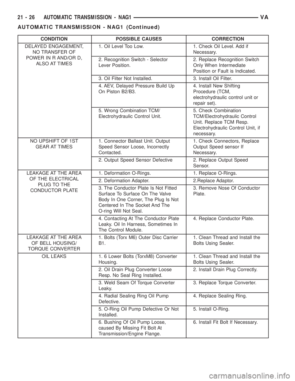
CONDITION POSSIBLE CAUSES CORRECTION
DELAYED ENGAGEMENT,
NO TRANSFER OF
POWER IN R AND/OR D,
ALSO AT TIMES1. Oil Level Too Low. 1. Check Oil Level. Add if
Necessary.
2. Recognition Switch - Selector
Lever Position.2. Replace Recognition Switch
Only When Intermediate
Position or Fault is Indicated.
3. Oil Filter Not Installed. 3. Install Oil Filter.
4. AEV, Delayed Pressure Build Up
On Piston B2/B3.4. Install New Shifting
Procedure (TCM,
electrohydraulic control unit or
repair set).
5. Wrong Combination TCM/
Electrohydraulic Control Unit.5. Check Combination
TCM/Electrohydraulic Control
Unit. Replace TCM Resp.
Electrohydraulic Control Unit, if
necessary.
NO UPSHIFT OF 1ST
GEAR AT TIMES1. Connector Ballast Unit. Output
Speed Sensor Loose, Incorrectly
Contacted.1. Check Connectors, Replace
Output Speed sensor If
Necessary.
2. Output Speed Sensor Defective 2. Replace Output Speed
Sensor.
LEAKAGE AT THE AREA
OF THE ELECTRICAL
PLUG TO THE
CONDUCTOR PLATE1. Deformation O-Rings. 1. Replace O-Rings.
2. Deformation Adapter. 2.Replace Adaptor.
3. The Conductor Plate Is Not Fitted
Surface To Surface On The Valve
Body In One Corner, The Plug Is Not
Centered In The Socket And The
O-ring Will Not Seal.3. Remove Nose Of Conductor
Plate.
4. Contacting At The Conductor Plate
Leaky. Oil In Harness, Sometimes In
The Control Module.4. Replace Conductor Plate.
LEAKAGE AT THE AREA
OF BELL HOUSING/
TORQUE CONVERTER1. Bolts (Torx M6) Outer Disc Carrier
B1.1. Clean Thread and Install the
Bolts Using Sealer.
OIL LEAKS 1. 6 Lower Bolts (TorxM8) Converter
Housing.1. Clean Thread and Install the
Bolts Using Sealer.
2. Oil Drain Plug Converter Loose
Resp. No Seal Ring Installed.2. Install Drain Plug Correctly.
3. Weld Seam Of Torque Converter
Leaky.3. Replace Torque Converter.
4. Radial Sealing Ring Oil Pump
Defective.4. Replace Sealing Ring.
5. O-Ring Oil Pump Defective Or Not
Installed.5. Install O-Ring.
6. Bushing Of Oil Pump Loose,
caused By Missing Fit Bolt At
Transmission/Engine Flange.6. Install Fit Bolt If Necessary.
21 - 26 AUTOMATIC TRANSMISSION - NAG1VA
AUTOMATIC TRANSMISSION - NAG1 (Continued)
Page 978 of 1232
DIAGNOSIS AND TESTING
DIAGNOSIS AND TESTING - EFFECTS OF
INCORRECT FLUID LEVEL
A low fluid level allows the pump to take in air
along with the fluid. Air in the fluid will cause fluid
pressures to be low and develop slower than normal.
If the transmission is overfilled, the gears churn the
fluid into foam. This aerates the fluid and causing
the same conditions occurring with a low level. In
either case, air bubbles cause fluid overheating, oxi-
dation and varnish buildup which interferes with
valve and clutch operation. Foaming also causes fluid
expansion which can result in fluid overflow from the
transmission vent or fill tube. Fluid overflow can eas-
ily be mistaken for a leak if inspection is not careful.
DIAGNOSIS AND TESTING - CAUSES OF
BURNT FLUID
Burnt, discolored fluid is a result of overheating
which has three primary causes.
(1) Internal clutch slippage, usually caused by low
line pressure, inadequate clutch apply pressure, or
clutch seal failure.
(2) A result of restricted fluid flow through the
main and/or auxiliary cooler. This condition is usu-
ally the result of a faulty or improperly installed
drainback valve, a damaged main cooler, or severe
restrictions in the coolers and lines caused by debris
or kinked lines.
(3) Heavy duty operation with a vehicle not prop-
erly equipped for this type of operation. Trailer tow-
ing or similar high load operation will overheat the
transmission fluid if the vehicle is improperly
equipped. Such vehicles should have an auxiliary
transmission fluid cooler, a heavy duty cooling sys-
tem, and the engine/axle ratio combination needed to
handle heavy loads.
DIAGNOSIS AND TESTING - FLUID
CONTAMINATION
Transmission fluid contamination is generally a
result of:
²adding incorrect fluid
²failure to clean dipstick and fill tube when
checking level
²engine coolant entering the fluid
²internal failure that generates debris
²overheat that generates sludge (fluid break-
down)
²failure to replace contaminated converter after
repair
The use of non-recommended fluids can result in
transmission failure. The usual results are erratic
shifts, slippage, abnormal wear and eventual failuredue to fluid breakdown and sludge formation. Avoid
this condition by using recommended fluids only.
The dipstick cap and fill tube should be wiped
clean before checking fluid level. Dirt, grease and
other foreign material on the cap and tube could fall
into the tube if not removed beforehand. Take the
time to wipe the cap and tube clean before withdraw-
ing the dipstick.
Engine coolant in the transmission fluid is gener-
ally caused by a cooler malfunction. The only remedy
is to replace the radiator as the cooler in the radiator
is not a serviceable part. If coolant has circulated
through the transmission, an overhaul is necessary.
The torque converter should be replaced whenever
a failure generates sludge and debris. This is neces-
sary because normal converter flushing procedures
will not remove all contaminants.
STANDARD PROCEDURE
STANDARD PROCEDURE - CHECK OIL LEVEL
(1) Verify that the vehicle is parked on a level sur-
face.
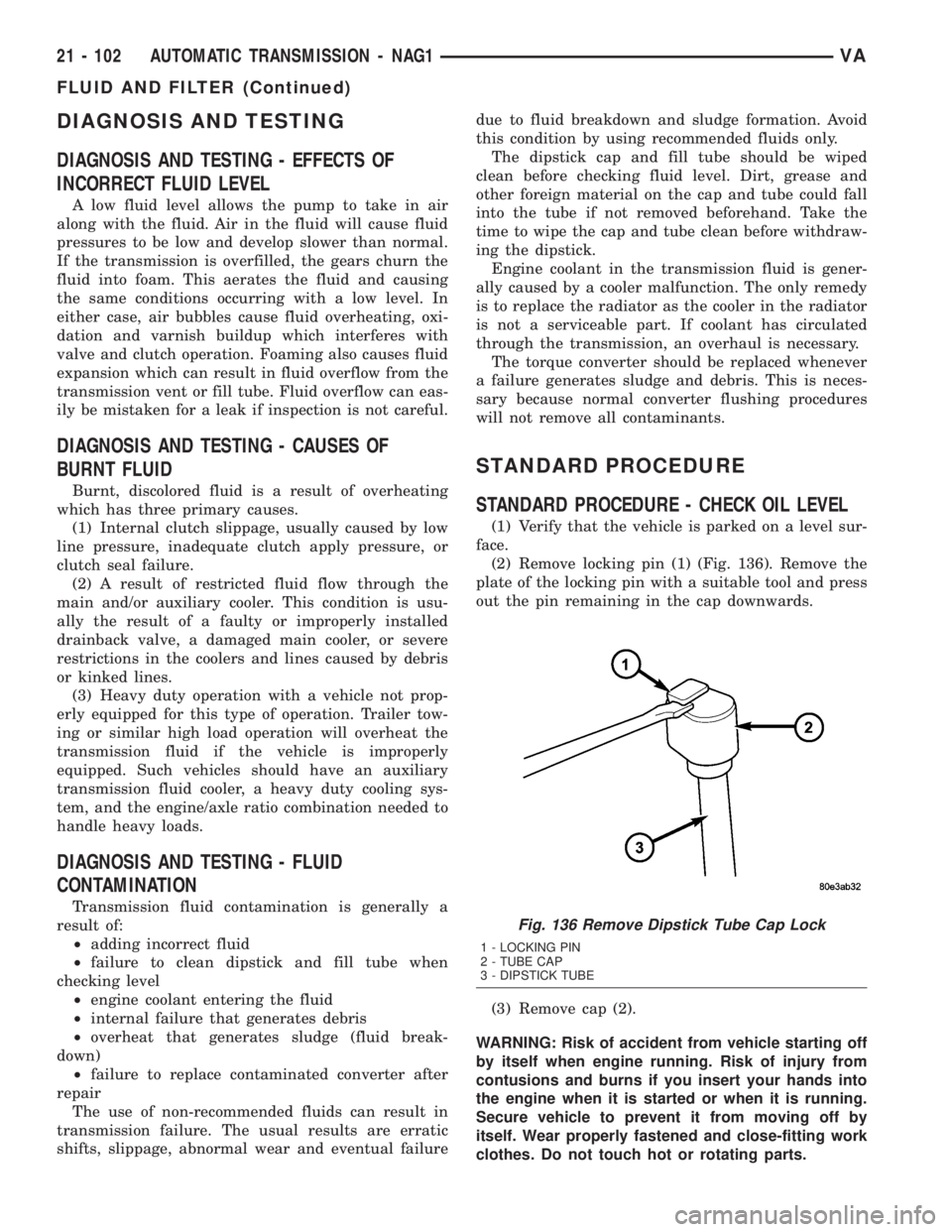
(2) Remove locking pin (1) (Fig. 136). Remove the
plate of the locking pin with a suitable tool and press
out the pin remaining in the cap downwards.
(3) Remove cap (2).
WARNING: Risk of accident from vehicle starting off
by itself when engine running. Risk of injury from
contusions and burns if you insert your hands into
the engine when it is started or when it is running.
Secure vehicle to prevent it from moving off by
itself. Wear properly fastened and close-fitting work
clothes. Do not touch hot or rotating parts.
Fig. 136 Remove Dipstick Tube Cap Lock
1 - LOCKING PIN
2 - TUBE CAP
3 - DIPSTICK TUBE
21 - 102 AUTOMATIC TRANSMISSION - NAG1VA
FLUID AND FILTER (Continued)
Page 1039 of 1232
BODY
TABLE OF CONTENTS
page page
BODY
WARNING
SAFETY PRECAUTIONS AND WARNINGS . . . 1
DIAGNOSIS AND TESTING
DIAGNOSIS AND TESTING - WATER LEAKS . 1
DIAGNOSIS AND TESTING - WIND NOISE . . . 2
STANDARD PROCEDURE
STANDARD PROCEDURE - PLASTIC BODY
PANEL REPAIR........................3
STANDARD PROCEDURE - BUZZ, SQUEAK
& RATTLE...........................10
SPECIFICATIONS.......................12DOOR - FRONT.........................13
DOORS - REAR.........................24
DOORS - SLIDING.......................36
EXTERIOR.............................47
HOOD.................................50
INSTRUMENT PANEL.....................53
INTERIOR..............................67
PAINT.................................74
SEATS................................76
STATIONARY GLASS.....................81
WEATHERSTRIP/SEALS...................87
BODY STRUCTURE......................88
BODY
WARNING
SAFETY PRECAUTIONS AND WARNINGS
WARNING: USE AN OSHA APPROVED BREATHING
FILTER WHEN SPRAYING PAINT OR SOLVENTS IN
A CONFINED AREA. PERSONAL INJURY CAN
RESULT.
²AVOID PROLONGED SKIN CONTACT WITH
PETROLEUM OR ALCOHOL ± BASED CLEANING
SOLVENTS. PERSONAL INJURY CAN RESULT.
²DO NOT STAND UNDER A HOISTED VEHICLE
THAT IS NOT PROPERLY SUPPORTED ON SAFETY
STANDS. PERSONAL INJURY CAN RESULT.
CAUTION: When holes must be drilled or punched
in an inner body panel, verify depth of space to the
outer body panel, electrical wiring, or other compo-
nents. Damage to vehicle can result.
²Do not weld exterior panels unless combustible
material on the interior of vehicle is removed from
the repair area. Fire or hazardous conditions, can
result.
²Always have a fire extinguisher ready for use
when welding.
²Disconnect the negative (-) cable clamp from
the battery when servicing electrical components
that are live when the ignition is OFF. Damage to
electrical system can result.
²Do not use abrasive chemicals or compounds
on painted surfaces. Damage to finish can result.²Do not use harsh alkaline based cleaning sol-
vents on painted or upholstered surfaces. Damage
to finish or color can result.
²Do not hammer or pound on plastic trim panel
when servicing interior trim. Plastic panels can
break.DIAGNOSIS AND TESTING
DIAGNOSIS AND TESTING - WATER LEAKS
Water leaks can be caused by poor sealing,
improper body component alignment, body seam
porosity, missing plugs, or blocked drain holes. Cen-
trifugal and gravitational force can cause water to
drip from a location away from the actual leak point,
making leak detection difficult. All body sealing
points should be water tight in normal wet-driving
conditions. Water flowing downward from the front of
the vehicle should not enter the passenger or luggage
compartment. Moving sealing surfaces will not
always seal water tight under all conditions. At
times, side glass or door seals will allow water to
enter the passenger compartment during high pres-
sure washing or hard driving rain (severe) condi-
tions. Overcompensating on door or glass
adjustments to stop a water leak that occurs under
severe conditions can cause premature seal wear and
excessive closing or latching effort. After completing
a repair, water test vehicle to verify leak has stopped
before returning vehicle to use.
VABODY 23 - 1
Page 1040 of 1232
VISUAL INSPECTION BEFORE WATER LEAK TESTS
Verify that floor and body plugs are in place, body
drains are clear, and body components are properly
aligned and sealed. If component alignment or seal-
ing is necessary, refer to the appropriate section of
this group for proper procedures.
WATER LEAK TESTS
WARNING: DO NOT USE ELECTRIC SHOP LIGHTS
OR TOOLS IN WATER TEST AREA. PERSONAL
INJURY CAN RESULT.
When the conditions causing a water leak have
been determined, simulate the conditions as closely
as possible.
²If a leak occurs with the vehicle parked in a
steady light rain, flood the leak area with an open-
ended garden hose.
²If a leak occurs while driving at highway speeds
in a steady rain, test the leak area with a reasonable
velocity stream or fan spray of water. Direct the
spray in a direction comparable to actual conditions.
²If a leak occurs when the vehicle is parked on an
incline, hoist the end or side of the vehicle to simu-
late this condition. This method can be used when
the leak occurs when the vehicle accelerates, stops or
turns. If the leak occurs on acceleration, hoist the
front of the vehicle. If the leak occurs when braking,
hoist the back of the vehicle. If the leak occurs on left
turns, hoist the left side of the vehicle. If the leak
occurs on right turns, hoist the right side of the vehi-
cle. For hoisting recommendations (Refer to LUBRI-
CATION & MAINTENANCE/HOISTING -
STANDARD PROCEDURE).
WATER LEAK DETECTION
To detect a water leak point-of-entry, do a water
test and watch for water tracks or droplets forming
on the inside of the vehicle. If necessary, remove inte-
rior trim covers or panels to gain visual access to the
leak area. If the hose cannot be positioned without
being held, have someone help do the water test.
Some water leaks must be tested for a considerable
length of time to become apparent. When a leak
appears, find the highest point of the water track or
drop. The highest point usually will show the point of
entry. After leak point has been found, repair the
leak and water test to verify that the leak has
stopped.
Locating the entry point of water that is leaking
into a cavity between panels can be difficult. The
trapped water may splash or run from the cavity,
often at a distance from the entry point. Most water
leaks of this type become apparent after accelerating,
stopping, turning, or when on an incline.MIRROR INSPECTION METHOD
When a leak point area is visually obstructed, use
a suitable mirror to gain visual access. A mirror can
also be used to deflect light to a limited-access area
to assist in locating a leak point.
BRIGHT LIGHT LEAK TEST METHOD
Some water leaks in the luggage compartment can
be detected without water testing. Position the vehi-
cle in a brightly lit area. From inside the darkened
luggage compartment inspect around seals and body
seams. If necessary, have a helper direct a drop light
over the suspected leak areas around the luggage
compartment. If light is visible through a normally
sealed location, water could enter through the open-
ing.
PRESSURIZED LEAK TEST METHOD
When a water leak into the passenger compart-
ment cannot be detected by water testing, pressurize
the passenger compartment and soap test exterior of
the vehicle. To pressurize the passenger compart-
ment, close all doors and windows, start engine, and
set heater control to high blower in HEAT position. If
engine can not be started, connect a charger to the
battery to ensure adequate voltage to the blower.
With interior pressurized, apply dish detergent solu-
tion to suspected leak area on the exterior of the
vehicle. Apply detergent solution with spray device or
soft bristle brush. If soap bubbles occur at a body
seam, joint, seal or gasket, the leak entry point could
be at that location.
DIAGNOSIS AND TESTING - WIND NOISE
Wind noise is the result of most air leaks. Air leaks
can be caused by poor sealing, improper body compo-
nent alignment, body seam porosity, or missing plugs
in the engine compartment or door hinge pillar areas.
All body sealing points should be airtight in normal
driving conditions. Moving sealing surfaces will not
always seal airtight under all conditions. At times,
side glass or door seals will allow wind noise to be
noticed in the passenger compartment during high
cross winds. Over compensating on door or glass
adjustments to stop wind noise that occurs under
severe conditions can cause premature seal wear and
excessive closing or latching effort. After a repair pro-
cedure has been performed, test vehicle to verify
noise has stopped before returning vehicle to use.
VISUAL INSPECTION BEFORE TESTS
Verify that floor and body plugs are in place and
body components are aligned and sealed. If compo-
nent alignment or sealing is necessary, refer to the
appropriate section of this group for proper proce-
dures.
23 - 2 BODYVA
BODY (Continued)
Page 1095 of 1232
INSTRUMENT PANEL
ASSEMBLY
REMOVAL
WARNING: ON VEHICLES EQUIPPED WITH AIR-
BAGS, DISABLE THE AIRBAG SYSTEM BEFORE
ATTEMPTING ANY STEERING WHEEL, STEERING
COLUMN, SEAT BELT TENSIONER, OR INSTRU-
MENT PANEL COMPONENT DIAGNOSIS OR SER-
VICE. DISCONNECT AND ISOLATE THE BATTERY
NEGATIVE (GROUND) CABLE, THEN WAIT TWO
MINUTES FOR THE AIRBAG SYSTEM CAPACITOR
TO DISCHARGE BEFORE PERFORMING FURTHER
DIAGNOSIS OR SERVICE. THIS IS THE ONLY SURE
WAY TO DISABLE THE AIRBAG SYSTEM. FAILURE
TO TAKE THE PROPER PRECAUTIONS COULD
RESULT IN ACCIDENTAL AIRBAG DEPLOYMENT
AND POSSIBLE PERSONAL INJURY.
²WHEN REMOVING A DEPLOYED AIRBAG, RUB-
BER GLOVES, EYE PROTECTION, AND A LONG-
SLEEVED SHIRT SHOULD BE WORN. THERE MAY
BE DEPOSITS ON THE AIRBAG UNIT AND OTHER
INTERIOR SURFACES. IN LARGE DOSES, THESE
DEPOSITS MAY CAUSE IRRITATION TO THE SKIN
AND EYES.
²USE EXTREME CARE TO PREVENT ANY FOR-
EIGN MATERIAL FROM ENTERING THE PASSEN-
GER AIRBAG, OR BECOMING ENTRAPPED
BETWEEN THE PASSENGER AIRBAG CUSHION
AND THE PASSENGER AIRBAG DOOR. FAILURE TO
OBSERVE THIS WARNING COULD RESULT IN
OCCUPANT INJURIES UPON AIRBAG DEPLOY-
MENT.
²THE PASSENGER AIRBAG DOOR MUST
NEVER BE PAINTED. REPLACEMENT PASSENGER
AIRBAGS ARE SERVICED WITH DOORS IN THE
ORIGINAL COLORS. PAINT MAY CHANGE THE WAY
IN WHICH THE MATERIAL OF THE AIRBAG DOOR
RESPONDS TO AN AIRBAG DEPLOYMENT. FAIL-
URE TO OBSERVE THIS WARNING COULD RESULT
IN OCCUPANT INJURIES UPON AIRBAG DEPLOY-
MENT.
(1) Disconnect and isolate the battery negative
cable.
(2) Remove radio. (Refer to 8 - ELECTRICAL/AU-
DIO/RADIO - REMOVAL)
(3) Remove glove compartment. (Refer to 23 -
BODY/INSTRUMENT PANEL/GLOVE BOX -
REMOVAL)
(4) Remove cup holder. (Refer to 23 - BODY/IN-
STRUMENT PANEL/CUP HOLDER - REMOVAL)
(5) Remove instrument cluster. (Refer to 8 - ELEC-
TRICAL/INSTRUMENT CLUSTER - REMOVAL)(6) Remove passenger airbag. (Refer to 8 - ELEC-
TRICAL/RESTRAINTS/PASSENGER AIRBAG -
REMOVAL)
(7) Remove right and left speakers. (Refer to 8 -
ELECTRICAL/AUDIO/SPEAKER - REMOVAL)
(8) Remove center bezel. (Refer to 23 - BODY/IN-
STRUMENT PANEL/INSTRUMENT PANEL CEN-
TER BEZEL - REMOVAL)
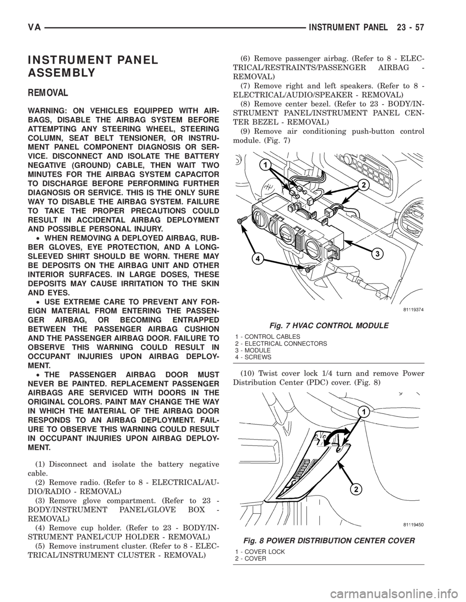
(9) Remove air conditioning push-button control
module. (Fig. 7)
(10) Twist cover lock 1/4 turn and remove Power
Distribution Center (PDC) cover. (Fig. 8)
Fig. 7 HVAC CONTROL MODULE
1 - CONTROL CABLES
2 - ELECTRICAL CONNECTORS
3 - MODULE
4 - SCREWS
Fig. 8 POWER DISTRIBUTION CENTER COVER
1 - COVER LOCK
2 - COVER
VAINSTRUMENT PANEL 23 - 57
Page 1100 of 1232
(13) Install left outer and inner air nozzles.
(14) Install left side cover and screws.
(15) Install passenger side air nozzle cover and
bracket and install the screws. (Fig. 12)
(16) Position Power Distribution Center (PDC) in
vehicle and connect electrical connectors. (Fig. 11)
(17) Install PDC and install bolt and nut. (Fig. 10)
(18) Install PDC ground cable and nut.
(19) Install steering column shroud and install the
two screws and one nut. (Fig. 9)
(20) Install PDC cover and twist lock 1/4 turn to
secure in place. (Fig. 8)
(21) Connect electrical connectors and cables to air
conditioning push-button module and install. (Fig. 7)
(22) Install center bezel. (Refer to 23 - BODY/IN-
STRUMENT PANEL/INSTRUMENT PANEL CEN-
TER BEZEL - INSTALLATION)
(23) Install left and right speakers. (Refer to 8 -
ELECTRICAL/AUDIO/SPEAKER - INSTALLATION)
(24) Install passenger airbag. (Refer to 8 - ELEC-
TRICAL/RESTRAINTS/PASSENGER AIRBAG -
INSTALLATION)
(25) Install instrument cluster. (Refer to 8 - ELEC-
TRICAL/INSTRUMENT CLUSTER - INSTALLA-
TION)
(26) Install cup holder. (Refer to 23 - BODY/IN-
STRUMENT PANEL/CUP HOLDER - INSTALLA-
TION)
(27) Install glove compartment. (Refer to 23 -
BODY/INSTRUMENT PANEL/GLOVE BOX -
INSTALLATION)
(28) Install radio. (Refer to 8 - ELECTRICAL/AU-
DIO/RADIO - INSTALLATION)
(29) Connect battery negative cable.
TOP COVER - CLUSTER
REMOVAL
WARNING: ON VEHICLES EQUIPPED WITH AIR-
BAGS, DISABLE THE AIRBAG SYSTEM BEFORE
ATTEMPTING ANY STEERING WHEEL, STEERING
COLUMN, SEAT BELT TENSIONER, OR INSTRU-
MENT PANEL COMPONENT DIAGNOSIS OR SER-
VICE. DISCONNECT AND ISOLATE THE BATTERY
NEGATIVE (GROUND) CABLE, THEN WAIT TWO
MINUTES FOR THE AIRBAG SYSTEM CAPACITOR
TO DISCHARGE BEFORE PERFORMING FURTHER
DIAGNOSIS OR SERVICE. THIS IS THE ONLY SURE
WAY TO DISABLE THE AIRBAG SYSTEM. FAILURE
TO TAKE THE PROPER PRECAUTIONS COULD
RESULT IN ACCIDENTAL AIRBAG DEPLOYMENT
AND POSSIBLE PERSONAL INJURY.
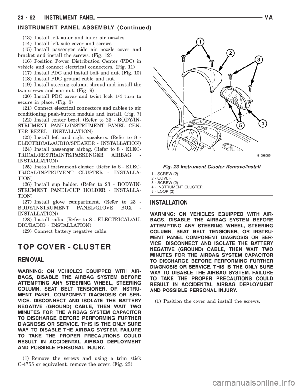
(1) Remove the screws and using a trim stick
C-4755 or equivalent, remove the cover. (Fig. 23)
INSTALLATION
WARNING: ON VEHICLES EQUIPPED WITH AIR-
BAGS, DISABLE THE AIRBAG SYSTEM BEFORE
ATTEMPTING ANY STEERING WHEEL, STEERING
COLUMN, SEAT BELT TENSIONER, OR INSTRU-
MENT PANEL COMPONENT DIAGNOSIS OR SER-
VICE. DISCONNECT AND ISOLATE THE BATTERY
NEGATIVE (GROUND) CABLE, THEN WAIT TWO
MINUTES FOR THE AIRBAG SYSTEM CAPACITOR
TO DISCHARGE BEFORE PERFORMING FURTHER
DIAGNOSIS OR SERVICE. THIS IS THE ONLY SURE
WAY TO DISABLE THE AIRBAG SYSTEM. FAILURE
TO TAKE THE PROPER PRECAUTIONS COULD
RESULT IN ACCIDENTAL AIRBAG DEPLOYMENT
AND POSSIBLE PERSONAL INJURY.
(1) Position the cover and install the screws.
Fig. 23 Instrument Cluster Remove/Install
1 - SCREW (2)
2 - COVER
3 - SCREW (2)
4 - INSTRUMENT CLUSTER
5 - LOOP (2)
23 - 62 INSTRUMENT PANELVA
INSTRUMENT PANEL ASSEMBLY (Continued)
Page 1129 of 1232
HEATING & AIR CONDITIONING
TABLE OF CONTENTS
page page
HEATING & AIR CONDITIONING
DESCRIPTION
DESCRIPTION - COOLING SYSTEM
REQUIREMENTS.......................1
DESCRIPTION - HEATER AND AIR
CONDITIONER........................1
OPERATION - HEATER AND AIR
CONDITIONER........................2
DIAGNOSIS AND TESTING
DIAGNOSIS AND TESTING - FUNCTION
TEST................................3
DIAGNOSIS AND TESTING - A/C
PERFORMANCE TEST..................3DIAGNOSIS AND TESTING - HEATER
PERFORMANCE.......................4
SPECIFICATIONS
A/C SYSTEM..........................5
CONTROLS - FRONT......................8
CONTROLS - REAR......................22
DISTRIBUTION - FRONT...................31
DISTRIBUTION - REAR....................39
PLUMBING.............................43
CABIN HEATER.........................72
HEATING & AIR
CONDITIONING
DESCRIPTION
DESCRIPTION - COOLING SYSTEM
REQUIREMENTS
To maintain the performance level of the heating-
air conditioning system, the engine cooling system
must be properly maintained. The use of a bug
screen is not recommended. Any obstructions in front
of the radiator or condenser will reduce the perfor-
mance of the air conditioning and engine cooling sys-
tems.
The engine cooling system includes the radiator,
thermostat, heater core, heater hoses and the engine
coolant pump. Refer to Cooling for more information
before opening or attempting any service to the
engine cooling system.
DESCRIPTION - HEATER AND AIR
CONDITIONER
A automatic temperature control (ATC) single zone
type heating-air conditioning system is standard
equipment on this model. A manually controlled rear
air conditioning system is available as a factory-in-
stalled option.
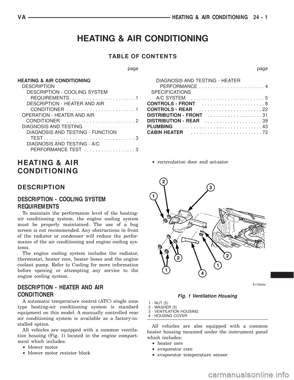
All vehicles are equipped with a common ventila-
tion housing (Fig. 1) located in the engine compart-
ment which includes:
²blower motor
²blower motor resistor block²recirculation door and actuator
All vehicles are also equipped with a common
heater housing mounted under the instrument panel
which includes:
²heater core
²evaporator core
²evaporator temperature sensor
Fig. 1 Ventilation Housing
1 - NUT (5)
2 - WASHER (5)
3 - VENTILATION HOUSING
4 - HOUSING COVER
VAHEATING & AIR CONDITIONING 24 - 1
Page 1130 of 1232
²expansion valve
²air outlet temperature sensor
²mode doors
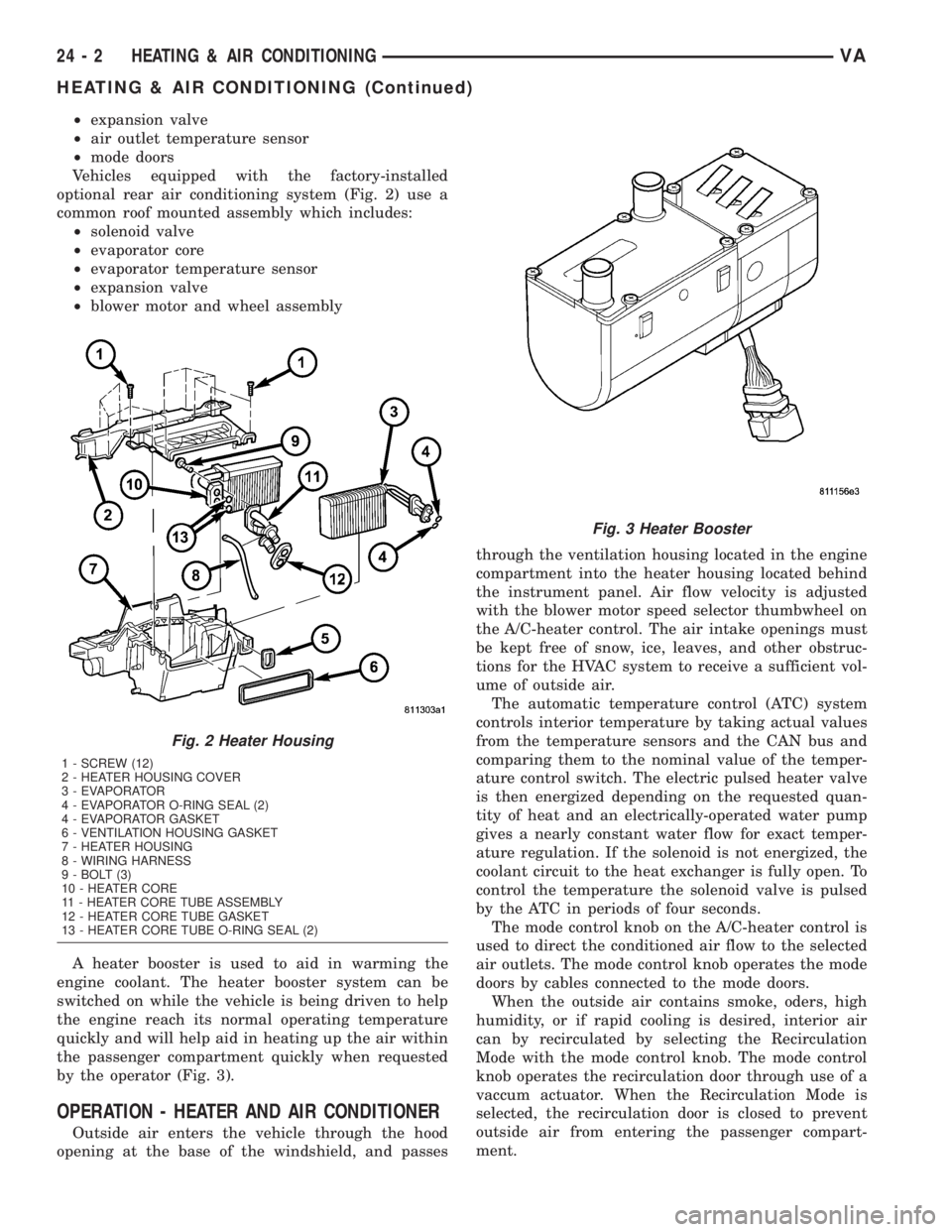
Vehicles equipped with the factory-installed
optional rear air conditioning system (Fig. 2) use a
common roof mounted assembly which includes:
²solenoid valve
²evaporator core
²evaporator temperature sensor
²expansion valve
²blower motor and wheel assembly
A heater booster is used to aid in warming the
engine coolant. The heater booster system can be
switched on while the vehicle is being driven to help
the engine reach its normal operating temperature
quickly and will help aid in heating up the air within
the passenger compartment quickly when requested
by the operator (Fig. 3).
OPERATION - HEATER AND AIR CONDITIONER
Outside air enters the vehicle through the hood
opening at the base of the windshield, and passesthrough the ventilation housing located in the engine
compartment into the heater housing located behind
the instrument panel. Air flow velocity is adjusted
with the blower motor speed selector thumbwheel on
the A/C-heater control. The air intake openings must
be kept free of snow, ice, leaves, and other obstruc-
tions for the HVAC system to receive a sufficient vol-
ume of outside air.
The automatic temperature control (ATC) system
controls interior temperature by taking actual values
from the temperature sensors and the CAN bus and
comparing them to the nominal value of the temper-
ature control switch. The electric pulsed heater valve
is then energized depending on the requested quan-
tity of heat and an electrically-operated water pump
gives a nearly constant water flow for exact temper-
ature regulation. If the solenoid is not energized, the
coolant circuit to the heat exchanger is fully open. To
control the temperature the solenoid valve is pulsed
by the ATC in periods of four seconds.
The mode control knob on the A/C-heater control is
used to direct the conditioned air flow to the selected
air outlets. The mode control knob operates the mode
doors by cables connected to the mode doors.
When the outside air contains smoke, oders, high
humidity, or if rapid cooling is desired, interior air
can by recirculated by selecting the Recirculation
Mode with the mode control knob. The mode control
knob operates the recirculation door through use of a
vaccum actuator. When the Recirculation Mode is
selected, the recirculation door is closed to prevent
outside air from entering the passenger compart-
ment.
Fig. 2 Heater Housing
1 - SCREW (12)
2 - HEATER HOUSING COVER
3 - EVAPORATOR
4 - EVAPORATOR O-RING SEAL (2)
4 - EVAPORATOR GASKET
6 - VENTILATION HOUSING GASKET
7 - HEATER HOUSING
8 - WIRING HARNESS
9 - BOLT (3)
10 - HEATER CORE
11 - HEATER CORE TUBE ASSEMBLY
12 - HEATER CORE TUBE GASKET
13 - HEATER CORE TUBE O-RING SEAL (2)
Fig. 3 Heater Booster
24 - 2 HEATING & AIR CONDITIONINGVA
HEATING & AIR CONDITIONING (Continued)