2005 MERCEDES-BENZ SPRINTER drain bolt
[x] Cancel search: drain boltPage 902 of 1232
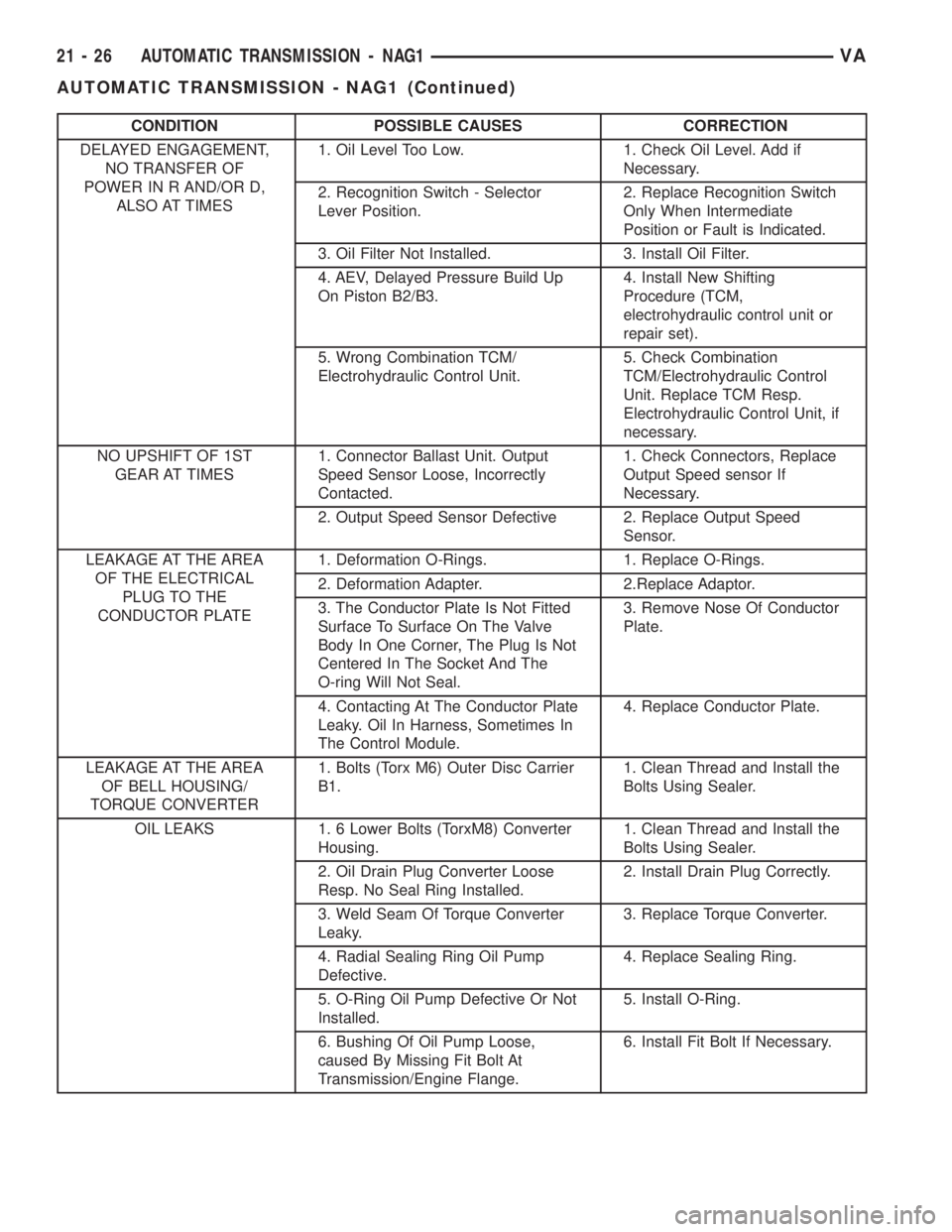
CONDITION POSSIBLE CAUSES CORRECTION
DELAYED ENGAGEMENT,
NO TRANSFER OF
POWER IN R AND/OR D,
ALSO AT TIMES1. Oil Level Too Low. 1. Check Oil Level. Add if
Necessary.
2. Recognition Switch - Selector
Lever Position.2. Replace Recognition Switch
Only When Intermediate
Position or Fault is Indicated.
3. Oil Filter Not Installed. 3. Install Oil Filter.
4. AEV, Delayed Pressure Build Up
On Piston B2/B3.4. Install New Shifting
Procedure (TCM,
electrohydraulic control unit or
repair set).
5. Wrong Combination TCM/
Electrohydraulic Control Unit.5. Check Combination
TCM/Electrohydraulic Control
Unit. Replace TCM Resp.
Electrohydraulic Control Unit, if
necessary.
NO UPSHIFT OF 1ST
GEAR AT TIMES1. Connector Ballast Unit. Output
Speed Sensor Loose, Incorrectly
Contacted.1. Check Connectors, Replace
Output Speed sensor If
Necessary.
2. Output Speed Sensor Defective 2. Replace Output Speed
Sensor.
LEAKAGE AT THE AREA
OF THE ELECTRICAL
PLUG TO THE
CONDUCTOR PLATE1. Deformation O-Rings. 1. Replace O-Rings.
2. Deformation Adapter. 2.Replace Adaptor.
3. The Conductor Plate Is Not Fitted
Surface To Surface On The Valve
Body In One Corner, The Plug Is Not
Centered In The Socket And The
O-ring Will Not Seal.3. Remove Nose Of Conductor
Plate.
4. Contacting At The Conductor Plate
Leaky. Oil In Harness, Sometimes In
The Control Module.4. Replace Conductor Plate.
LEAKAGE AT THE AREA
OF BELL HOUSING/
TORQUE CONVERTER1. Bolts (Torx M6) Outer Disc Carrier
B1.1. Clean Thread and Install the
Bolts Using Sealer.
OIL LEAKS 1. 6 Lower Bolts (TorxM8) Converter
Housing.1. Clean Thread and Install the
Bolts Using Sealer.
2. Oil Drain Plug Converter Loose
Resp. No Seal Ring Installed.2. Install Drain Plug Correctly.
3. Weld Seam Of Torque Converter
Leaky.3. Replace Torque Converter.
4. Radial Sealing Ring Oil Pump
Defective.4. Replace Sealing Ring.
5. O-Ring Oil Pump Defective Or Not
Installed.5. Install O-Ring.
6. Bushing Of Oil Pump Loose,
caused By Missing Fit Bolt At
Transmission/Engine Flange.6. Install Fit Bolt If Necessary.
21 - 26 AUTOMATIC TRANSMISSION - NAG1VA
AUTOMATIC TRANSMISSION - NAG1 (Continued)
Page 903 of 1232
STANDARD PROCEDURE - ALUMINUM
THREAD REPAIR
Damaged or worn threads in the aluminum trans-
mission case and valve body can be repaired by the
use of Heli-CoilsŸ, or equivalent. This repair con-
sists of drilling out the worn-out damaged threads.
Then tap the hole with a special Heli-CoilŸ tap, or
equivalent, and installing a Heli-CoilŸ insert, or
equivalent, into the hole. This brings the hole back to
its original thread size.
Heli-CoilŸ, or equivalent, tools and inserts are
readily available from most automotive parts suppli-
ers.
REMOVAL
(1) Disconnect the negative (ground) battery cable.
CAUTION: Isolate ground lead to prevent accidental
contact.
(2) Apply parking brake.
(3) Move gear selector lever to position9N9.
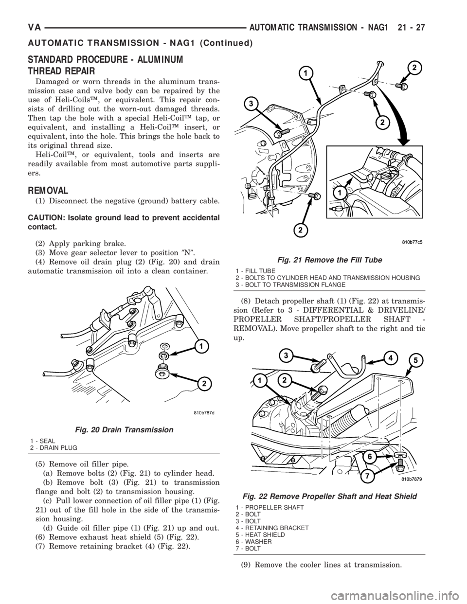
(4) Remove oil drain plug (2) (Fig. 20) and drain
automatic transmission oil into a clean container.
(5) Remove oil filler pipe.
(a) Remove bolts (2) (Fig. 21) to cylinder head.
(b) Remove bolt (3) (Fig. 21) to transmission
flange and bolt (2) to transmission housing.
(c) Pull lower connection of oil filler pipe (1) (Fig.
21) out of the fill hole in the side of the transmis-
sion housing.
(d) Guide oil filler pipe (1) (Fig. 21) up and out.
(6) Remove exhaust heat shield (5) (Fig. 22).
(7) Remove retaining bracket (4) (Fig. 22).(8) Detach propeller shaft (1) (Fig. 22) at transmis-
sion (Refer to 3 - DIFFERENTIAL & DRIVELINE/
PROPELLER SHAFT/PROPELLER SHAFT -
REMOVAL). Move propeller shaft to the right and tie
up.
(9) Remove the cooler lines at transmission.
Fig. 20 Drain Transmission
1 - SEAL
2 - DRAIN PLUG
Fig. 21 Remove the Fill Tube
1 - FILL TUBE
2 - BOLTS TO CYLINDER HEAD AND TRANSMISSION HOUSING
3 - BOLT TO TRANSMISSION FLANGE
Fig. 22 Remove Propeller Shaft and Heat Shield
1 - PROPELLER SHAFT
2 - BOLT
3 - BOLT
4 - RETAINING BRACKET
5 - HEAT SHIELD
6 - WASHER
7 - BOLT
VAAUTOMATIC TRANSMISSION - NAG1 21 - 27
AUTOMATIC TRANSMISSION - NAG1 (Continued)
Page 907 of 1232
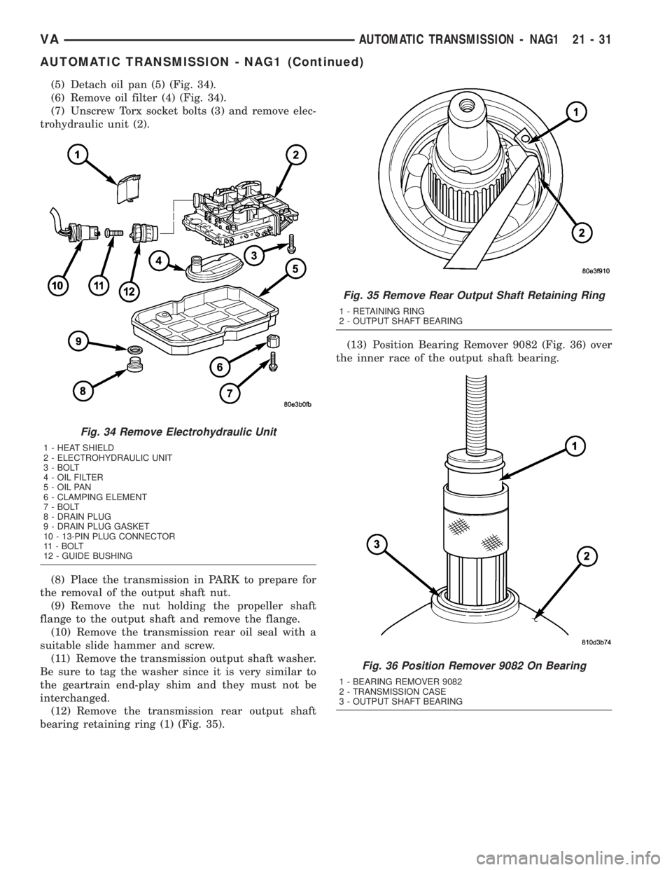
(5) Detach oil pan (5) (Fig. 34).
(6) Remove oil filter (4) (Fig. 34).
(7) Unscrew Torx socket bolts (3) and remove elec-
trohydraulic unit (2).
(8) Place the transmission in PARK to prepare for
the removal of the output shaft nut.
(9) Remove the nut holding the propeller shaft
flange to the output shaft and remove the flange.
(10) Remove the transmission rear oil seal with a
suitable slide hammer and screw.
(11) Remove the transmission output shaft washer.
Be sure to tag the washer since it is very similar to
the geartrain end-play shim and they must not be
interchanged.
(12) Remove the transmission rear output shaft
bearing retaining ring (1) (Fig. 35).(13) Position Bearing Remover 9082 (Fig. 36) over
the inner race of the output shaft bearing.
Fig. 34 Remove Electrohydraulic Unit
1 - HEAT SHIELD
2 - ELECTROHYDRAULIC UNIT
3 - BOLT
4 - OIL FILTER
5 - OIL PAN
6 - CLAMPING ELEMENT
7 - BOLT
8 - DRAIN PLUG
9 - DRAIN PLUG GASKET
10 - 13-PIN PLUG CONNECTOR
11 - BOLT
12 - GUIDE BUSHING
Fig. 35 Remove Rear Output Shaft Retaining Ring
1 - RETAINING RING
2 - OUTPUT SHAFT BEARING
Fig. 36 Position Remover 9082 On Bearing
1 - BEARING REMOVER 9082
2 - TRANSMISSION CASE
3 - OUTPUT SHAFT BEARING
VAAUTOMATIC TRANSMISSION - NAG1 21 - 31
AUTOMATIC TRANSMISSION - NAG1 (Continued)
Page 917 of 1232
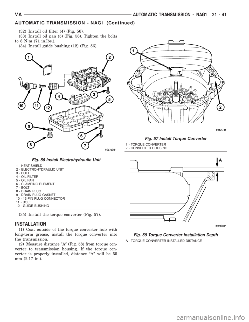
(32) Install oil filter (4) (Fig. 56).
(33) Install oil pan (5) (Fig. 56). Tighten the bolts
to 8 N´m (71 in.lbs.).
(34) Install guide bushing (12) (Fig. 56).
(35) Install the torque converter (Fig. 57).
INSTALLATION
(1) Coat outside of the torque converter hub with
long-term grease, install the torque converter into
the transmission.
(2) Measure distance9A9(Fig. 58) from torque con-
verter to transmission housing. If the torque con-
verter is properly installed, distance ªAº will be 55
mm (2.17 in.).
Fig. 56 Install Electrohydraulic Unit
1 - HEAT SHIELD
2 - ELECTROHYDRAULIC UNIT
3 - BOLT
4 - OIL FILTER
5 - OIL PAN
6 - CLAMPING ELEMENT
7 - BOLT
8 - DRAIN PLUG
9 - DRAIN PLUG GASKET
10 - 13-PIN PLUG CONNECTOR
11 - BOLT
12 - GUIDE BUSHING
Fig. 57 Install Torque Converter
1 - TORQUE CONVERTER
2 - CONVERTER HOUSING
Fig. 58 Torque Converter Installation Depth
A - TORQUE CONVERTER INSTALLED DISTANCE
VAAUTOMATIC TRANSMISSION - NAG1 21 - 41
AUTOMATIC TRANSMISSION - NAG1 (Continued)
Page 945 of 1232
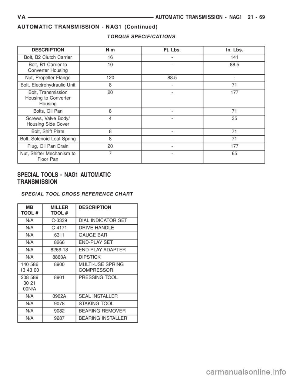
TORQUE SPECIFICATIONS
DESCRIPTION N´m Ft. Lbs. In. Lbs.
Bolt, B2 Clutch Carrier 16 - 141
Bolt, B1 Carrier to
Converter Housing10 - 88.5
Nut, Propeller Flange 120 88.5 -
Bolt, Electrohydraulic Unit 8 - 71
Bolt, Transmission
Housing to Converter
Housing20 - 177
Bolts, Oil Pan 8 - 71
Screws, Valve Body/
Housing Side Cover4-35
Bolt, Shift Plate 8 - 71
Bolt, Solenoid Leaf Spring 8 - 71
Plug, Oil Pan Drain 20 - 177
Nut, Shifter Mechanism to
Floor Pan7-65
SPECIAL TOOLS - NAG1 AUTOMATIC
TRANSMISSION
SPECIAL TOOL CROSS REFERENCE CHART
MB
TOOL #MILLER
TOOL #DESCRIPTION
N/A C-3339 DIAL INDICATOR SET
N/A C-4171 DRIVE HANDLE
N/A 6311 GAUGE BAR
N/A 8266 END-PLAY SET
N/A 8266-18 END-PLAY ADAPTER
N/A 8863A DIPSTICK
140 586
13 43 008900 MULTI-USE SPRING
COMPRESSOR
208 589
00 21
00N/A8901 PRESSING TOOL
N/A 8902A SEAL INSTALLER
N/A 9078 STAKING TOOL
N/A 9082 BEARING REMOVER
N/A 9287 BEARING INSTALLER
VAAUTOMATIC TRANSMISSION - NAG1 21 - 69
AUTOMATIC TRANSMISSION - NAG1 (Continued)
Page 968 of 1232
REMOVAL
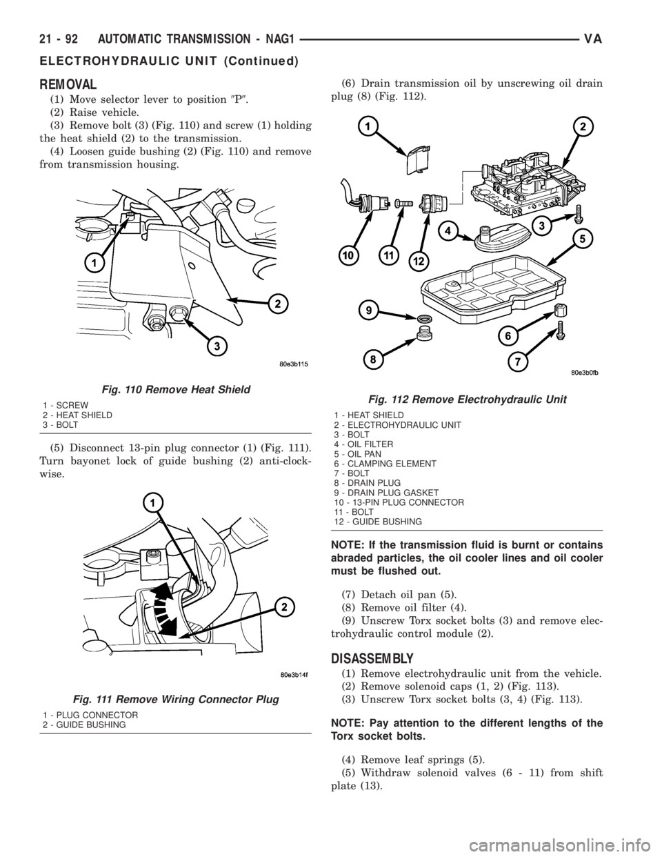
(1) Move selector lever to position9P9.
(2) Raise vehicle.
(3) Remove bolt (3) (Fig. 110) and screw (1) holding
the heat shield (2) to the transmission.
(4) Loosen guide bushing (2) (Fig. 110) and remove
from transmission housing.
(5) Disconnect 13-pin plug connector (1) (Fig. 111).
Turn bayonet lock of guide bushing (2) anti-clock-
wise.(6) Drain transmission oil by unscrewing oil drain
plug (8) (Fig. 112).
NOTE: If the transmission fluid is burnt or contains
abraded particles, the oil cooler lines and oil cooler
must be flushed out.
(7) Detach oil pan (5).
(8) Remove oil filter (4).
(9) Unscrew Torx socket bolts (3) and remove elec-
trohydraulic control module (2).
DISASSEMBLY
(1) Remove electrohydraulic unit from the vehicle.
(2) Remove solenoid caps (1, 2) (Fig. 113).
(3) Unscrew Torx socket bolts (3, 4) (Fig. 113).
NOTE: Pay attention to the different lengths of the
Torx socket bolts.
(4) Remove leaf springs (5).
(5) Withdraw solenoid valves (6 - 11) from shift
plate (13).
Fig. 110 Remove Heat Shield
1 - SCREW
2 - HEAT SHIELD
3 - BOLT
Fig. 111 Remove Wiring Connector Plug
1 - PLUG CONNECTOR
2 - GUIDE BUSHING
Fig. 112 Remove Electrohydraulic Unit
1 - HEAT SHIELD
2 - ELECTROHYDRAULIC UNIT
3 - BOLT
4 - OIL FILTER
5 - OIL PAN
6 - CLAMPING ELEMENT
7 - BOLT
8 - DRAIN PLUG
9 - DRAIN PLUG GASKET
10 - 13-PIN PLUG CONNECTOR
11 - BOLT
12 - GUIDE BUSHING
21 - 92 AUTOMATIC TRANSMISSION - NAG1VA
ELECTROHYDRAULIC UNIT (Continued)
Page 976 of 1232
INSTALLATION
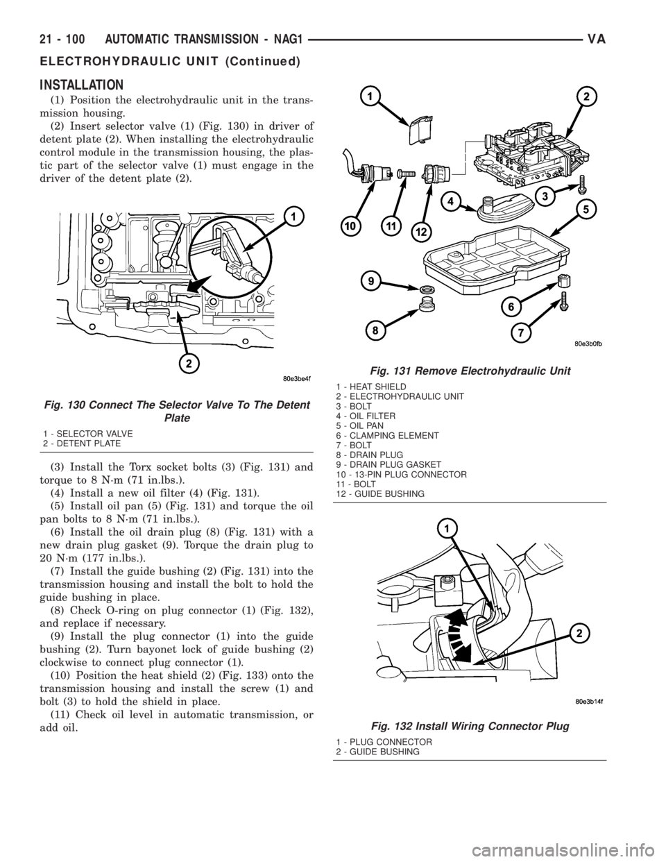
(1) Position the electrohydraulic unit in the trans-
mission housing.
(2) Insert selector valve (1) (Fig. 130) in driver of
detent plate (2). When installing the electrohydraulic
control module in the transmission housing, the plas-
tic part of the selector valve (1) must engage in the
driver of the detent plate (2).
(3) Install the Torx socket bolts (3) (Fig. 131) and
torque to 8 N´m (71 in.lbs.).
(4) Install a new oil filter (4) (Fig. 131).
(5) Install oil pan (5) (Fig. 131) and torque the oil
pan bolts to 8 N´m (71 in.lbs.).
(6) Install the oil drain plug (8) (Fig. 131) with a
new drain plug gasket (9). Torque the drain plug to
20 N´m (177 in.lbs.).
(7) Install the guide bushing (2) (Fig. 131) into the
transmission housing and install the bolt to hold the
guide bushing in place.
(8) Check O-ring on plug connector (1) (Fig. 132),
and replace if necessary.
(9) Install the plug connector (1) into the guide
bushing (2). Turn bayonet lock of guide bushing (2)
clockwise to connect plug connector (1).
(10) Position the heat shield (2) (Fig. 133) onto the
transmission housing and install the screw (1) and
bolt (3) to hold the shield in place.
(11) Check oil level in automatic transmission, or
add oil.
Fig. 130 Connect The Selector Valve To The Detent
Plate
1 - SELECTOR VALVE
2 - DETENT PLATE
Fig. 131 Remove Electrohydraulic Unit
1 - HEAT SHIELD
2 - ELECTROHYDRAULIC UNIT
3 - BOLT
4 - OIL FILTER
5 - OIL PAN
6 - CLAMPING ELEMENT
7 - BOLT
8 - DRAIN PLUG
9 - DRAIN PLUG GASKET
10 - 13-PIN PLUG CONNECTOR
11 - BOLT
12 - GUIDE BUSHING
Fig. 132 Install Wiring Connector Plug
1 - PLUG CONNECTOR
2 - GUIDE BUSHING
21 - 100 AUTOMATIC TRANSMISSION - NAG1VA
ELECTROHYDRAULIC UNIT (Continued)
Page 980 of 1232
(a) If only fluid and filter were changed, add5.0
L (10.6 pts.)of transmission fluid to transmission.
(b) If transmission was completely overhauled,
torque converter was replaced or drained, and
cooler was flushed, add7.7 L (16.3 pts.)of trans-
mission fluid to transmission.
(5) Check the transmission fluid (Refer to 21 -
TRANSMISSION/AUTOMATIC - NAG1/FLUID -
STANDARD PROCEDURE) and adjust as required.
STANDARD PROCEDURE - FLUID/FILTER
SERVICE
(1) Run the engine until the transmission oil
reaches operating temperature.
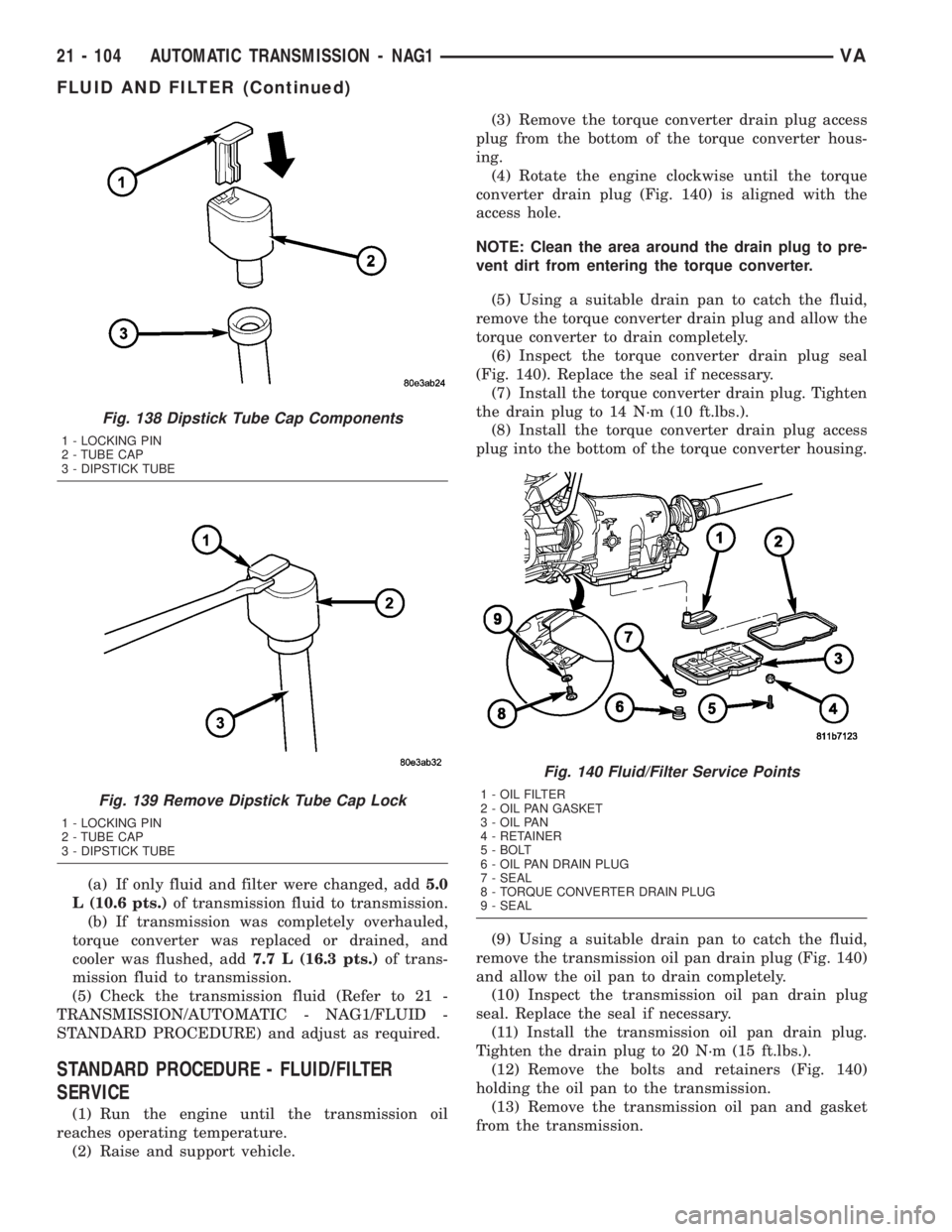
(2) Raise and support vehicle.(3) Remove the torque converter drain plug access
plug from the bottom of the torque converter hous-
ing.
(4) Rotate the engine clockwise until the torque
converter drain plug (Fig. 140) is aligned with the
access hole.
NOTE: Clean the area around the drain plug to pre-
vent dirt from entering the torque converter.
(5) Using a suitable drain pan to catch the fluid,
remove the torque converter drain plug and allow the
torque converter to drain completely.
(6) Inspect the torque converter drain plug seal
(Fig. 140). Replace the seal if necessary.
(7) Install the torque converter drain plug. Tighten
the drain plug to 14 N´m (10 ft.lbs.).
(8) Install the torque converter drain plug access
plug into the bottom of the torque converter housing.
(9) Using a suitable drain pan to catch the fluid,
remove the transmission oil pan drain plug (Fig. 140)
and allow the oil pan to drain completely.
(10) Inspect the transmission oil pan drain plug
seal. Replace the seal if necessary.
(11) Install the transmission oil pan drain plug.
Tighten the drain plug to 20 N´m (15 ft.lbs.).
(12) Remove the bolts and retainers (Fig. 140)
holding the oil pan to the transmission.
(13) Remove the transmission oil pan and gasket
from the transmission.
Fig. 138 Dipstick Tube Cap Components
1 - LOCKING PIN
2 - TUBE CAP
3 - DIPSTICK TUBE
Fig. 139 Remove Dipstick Tube Cap Lock
1 - LOCKING PIN
2 - TUBE CAP
3 - DIPSTICK TUBE
Fig. 140 Fluid/Filter Service Points
1 - OIL FILTER
2 - OIL PAN GASKET
3 - OIL PAN
4 - RETAINER
5 - BOLT
6 - OIL PAN DRAIN PLUG
7 - SEAL
8 - TORQUE CONVERTER DRAIN PLUG
9 - SEAL
21 - 104 AUTOMATIC TRANSMISSION - NAG1VA
FLUID AND FILTER (Continued)