2005 MERCEDES-BENZ SPRINTER drain bolt
[x] Cancel search: drain boltPage 1206 of 1232

INSTALLATION
INSTALLATION
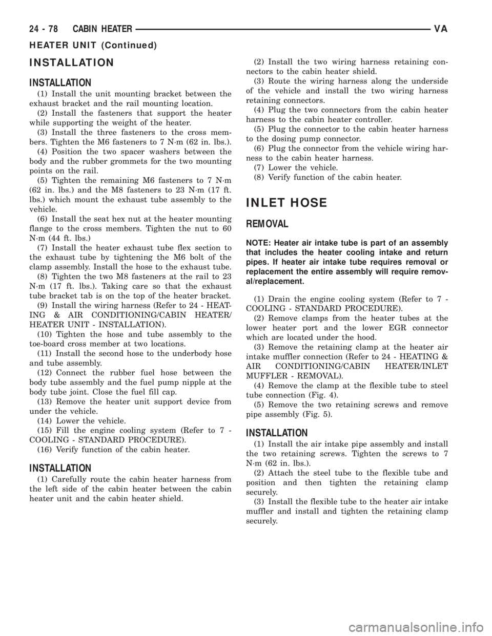
(1) Install the unit mounting bracket between the
exhaust bracket and the rail mounting location.
(2) Install the fasteners that support the heater
while supporting the weight of the heater.
(3) Install the three fasteners to the cross mem-
bers. Tighten the M6 fasteners to 7 N´m (62 in. lbs.).
(4) Position the two spacer washers between the
body and the rubber grommets for the two mounting
points on the rail.
(5) Tighten the remaining M6 fasteners to 7 N´m
(62 in. lbs.) and the M8 fasteners to 23 N´m (17 ft.
lbs.) which mount the exhaust tube assembly to the
vehicle.
(6) Install the seat hex nut at the heater mounting
flange to the cross members. Tighten the nut to 60
N´m (44 ft. lbs.)
(7) Install the heater exhaust tube flex section to
the exhaust tube by tightening the M6 bolt of the
clamp assembly. Install the hose to the exhaust tube.
(8) Tighten the two M8 fasteners at the rail to 23
N´m (17 ft. lbs.). Taking care so that the exhaust
tube bracket tab is on the top of the heater bracket.
(9) Install the wiring harness (Refer to 24 - HEAT-
ING & AIR CONDITIONING/CABIN HEATER/
HEATER UNIT - INSTALLATION).
(10) Tighten the hose and tube assembly to the
toe-board cross member at two locations.
(11) Install the second hose to the underbody hose
and tube assembly.
(12) Connect the rubber fuel hose between the
body tube assembly and the fuel pump nipple at the
body tube joint. Close the fuel fill cap.
(13) Remove the heater unit support device from
under the vehicle.
(14) Lower the vehicle.
(15) Fill the engine cooling system (Refer to 7 -
COOLING - STANDARD PROCEDURE).
(16) Verify function of the cabin heater.
INSTALLATION
(1) Carefully route the cabin heater harness from
the left side of the cabin heater between the cabin
heater unit and the cabin heater shield.(2) Install the two wiring harness retaining con-
nectors to the cabin heater shield.
(3) Route the wiring harness along the underside
of the vehicle and install the two wiring harness
retaining connectors.
(4) Plug the two connectors from the cabin heater
harness to the cabin heater controller.
(5) Plug the connector to the cabin heater harness
to the dosing pump connector.
(6) Plug the connector from the vehicle wiring har-
ness to the cabin heater harness.
(7) Lower the vehicle.
(8) Verify function of the cabin heater.
INLET HOSE
REMOVAL
NOTE: Heater air intake tube is part of an assembly
that includes the heater cooling intake and return
pipes. If heater air intake tube requires removal or
replacement the entire assembly will require remov-
al/replacement.
(1) Drain the engine cooling system (Refer to 7 -
COOLING - STANDARD PROCEDURE).
(2) Remove clamps from the heater tubes at the
lower heater port and the lower EGR connector
which are located under the hood.
(3) Remove the retaining clamp at the heater air
intake muffler connection (Refer to 24 - HEATING &
AIR CONDITIONING/CABIN HEATER/INLET
MUFFLER - REMOVAL).
(4) Remove the clamp at the flexible tube to steel
tube connection (Fig. 4).
(5) Remove the two retaining screws and remove
pipe assembly (Fig. 5).
INSTALLATION
(1) Install the air intake pipe assembly and install
the two retaining screws. Tighten the screws to 7
N´m (62 in. lbs.).
(2) Attach the steel tube to the flexible tube and
position and then tighten the retaining clamp
securely.
(3) Install the flexible tube to the heater air intake
muffler and install and tighten the retaining clamp
securely.
24 - 78 CABIN HEATERVA
HEATER UNIT (Continued)
Page 1215 of 1232

COVER - REMOVAL, TIMING CHAIN.......9-59
COVER - REMOVAL, TOP..............23-64
COVER - TRAY - INSTALLATION, TOP.....23-64
COVER - TRAY - REMOVAL, TOP........23-63
COVER(S) - INSTALLATION, CYLINDER
HEAD...............................9-30
COVER(S) - REMOVAL, CYLINDER HEAD . . . 9-30
COWL TRIM - INSTALLATION...........23-70
COWL TRIM - REMOVAL...............23-70
CRADLE CROSSMEMBER -
INSTALLATION, ENGINE................13-8
CRADLE CROSSMEMBER - REMOVAL,
ENGINE.............................13-6
CRANKSHAFT - INSTALLATION...........9-36
CRANKSHAFT - REMOVAL..............9-35
CRANKSHAFT AND BLOCK JOURNALS -
STANDARD PROCEDURE, MEASURE......9-35
CRANKSHAFT OIL SEAL - FRONT -
INSTALLATION........................9-38
CRANKSHAFT OIL SEAL - FRONT -
REMOVAL...........................9-38
CRANKSHAFT OIL SEAL - REAR -
INSTALLATION........................9-37
CRANKSHAFT OIL SEAL - REAR -
REMOVAL...........................9-37
CRANKSHAFT POSITION SENSOR -
DESCRIPTION.......................14-20
CRANKSHAFT POSITION SENSOR -
INSTALLATION.......................14-20
CRANKSHAFT POSITION SENSOR -
OPERATION..........................14-20
CRANKSHAFT POSITION SENSOR -
REMOVAL..........................14-20
CROSSMEMBER - INSTALLATION,
ENGINE CRADLE......................13-8
CROSSMEMBER - INSTALLATION,
RADIATOR..........................23-48
CROSSMEMBER - REMOVAL, ENGINE
CRADLE.............................13-6
CROSSMEMBER - REMOVAL, RADIATOR . . 23-47
CROSSMEMBER - TRANSMISSION -
INSTALLATION, REAR..................13-9
CROSSMEMBER - TRANSMISSION -
REMOVAL, REAR......................13-9
CUP HOLDER - INSTALLATION..........23-56
CUP HOLDER - REMOVAL..............23-55
CUSHION - FRONT - INSTALLATION,
SEAT ..............................23-78
CUSHION - FRONT - REMOVAL, SEAT....23-78
CUSHION/COVER - REAR -
INSTALLATION, SEAT.................23-80
CUSHION/COVER - REAR -
INSTALLATION, SEAT BACK............23-80
CUSHION/COVER - REAR - REMOVAL,
SEAT
..............................23-80
CUSHION/COVER - REAR - REMOVAL,
SEAT BACK
.........................23-80
CYLINDER - INSTALLATION, KEY/LOCK
....19-7
CYLINDER - INSTALLATION, LOCK
.......23-18
CYLINDER - INSTALLATION, MASTER
.....5-18
CYLINDER - REMOVAL, KEY/LOCK
........19-6
CYLINDER - REMOVAL, LOCK
...........23-18
CYLINDER - REMOVAL, MASTER
.........5-17
CYLINDER BLEEDING - STANDARD
PROCEDURE, MASTER
.................5-17
CYLINDER BORES - STANDARD
PROCEDURE, MEASURING
..............9-34
CYLINDER HEAD - INSTALLATION
........9-25
CYLINDER HEAD - REMOVAL
............9-22
CYLINDER HEAD BOLT INSPECTION -
STANDARD PROCEDURE
................9-21
CYLINDER HEAD COVER(S) -
INSTALLATION
........................9-30
CYLINDER HEAD COVER(S) - REMOVAL
. . . 9-30
CYLINDER HEAD FRONT COVER -
INSTALLATION
........................9-26
CYLINDER HEAD FRONT COVER -
REMOVAL
...........................9-23
CYLINDER HEAD GUIDE RAIL -
INSTALLATION
........................9-26
CYLINDER HEAD GUIDE RAIL -
REMOVAL
...........................9-24
CYLINDER HEAD SURFACE - STANDARD
PROCEDURE, MEASURE
................9-21
CYLINDER LEAK DOWN TEST -
STANDARD PROCEDURE
.................9-3CYLINDER PRESSURE LOSS -
STANDARD PROCEDURE,
DETERMINING.........................9-4
CYLINDER/POWER BOOSTER -
DIAGNOSIS AND TESTING, MASTER......5-16
DAMPER - INSTALLATION, VIBRATION.....9-48
DAMPER - REMOVAL, VIBRATION........9-47
DAYTIME RUNNING LAMP RELAY -
INSTALLATION........................8L-9
DAYTIME RUNNING LAMP RELAY -
REMOVAL...........................8L-9
DCHA - DIAGNOSIS AND TESTING,
DIESEL SUPPLEMENTAL HEATER........24-72
DECOUPLER - DIAGNOSIS AND
TESTING, GENERATOR................8F-19
DECOUPLER PULLEY - DESCRIPTION,
GENERATOR........................8F-19
DECOUPLER PULLEY - INSTALLATION,
GENERATOR........................8F-21
DECOUPLER PULLEY - OPERATION,
GENERATOR........................8F-19
DECOUPLER PULLEY - REMOVAL,
GENERATOR........................8F-20
DEFROSTER DUCTS - INSTALLATION.....24-33
DEFROSTER DUCTS - REMOVAL.........24-33
DELAY RELAY - INSTALLATION, TIME....8L-33
DELAY RELAY - REMOVAL, TIME........8L-32
DEPLOYMENT - STANDARD
PROCEDURE, SERVICE AFTER A
SUPPLEMENTAL RESTRAINT............8O-6
DETERMINING CYLINDER PRESSURE
LOSS - STANDARD PROCEDURE..........9-4
DEVICES - STANDARD PROCEDURE,
ELECTROSTATIC DISCHARGE (ESD)
SENSITIVE........................8W-01-7
DIAGRAMS - DESCRIPTION, HOW TO
USE WIRING......................8W-01-1
DIAGRAMS, DIAGNOSIS AND TESTING -
SCHEMATICS........................21-47
DIESEL - DESCRIPTION, 2.7L............11-1
DIESEL - SPECIFICATIONS, STARTER
MOTOR............................8F-29
DIESEL - TORQUE, 2.7L...............8F-17
DIESEL - TORQUE, STARTER...........8F-29
DIESEL ENGINE - DESCRIPTION, FUEL
REQUIREMENTS.......................0-1
DIESEL ENGINE - DIAGNOSIS AND
TESTING............................11-2
DIESEL ENGINES - DESCRIPTION,
ENGINE OIL...........................0-3
DIESEL SUPPLEMENTAL HEATER - DCHA
- DIAGNOSIS AND TESTING............24-72
DIMENSIONS - SPECIFICATIONS, FRAME . . . 13-4
DIMENSIONS - SPECIFICATIONS,
OPENING...........................23-90
DIODE - INSTALLATION.............8W-01-9
DIODE - REMOVAL.................8W-01-9
DISCHARGE (ESD) SENSITIVE DEVICES -
STANDARD PROCEDURE,
ELECTROSTATIC...................8W-01-7
DISCHARGE LINE - INSTALLATION, A/C . . . 24-54
DISCHARGE LINE - REMOVAL, A/C.......24-53
DISCONNECTING AND CONNECTING
FUEL LINES - STANDARD PROCEDURE....14-2
DISTRIBUTION - DESCRIPTION,
POWER..........................8W-97-1
DISTRIBUTION - OPERATION, POWER . . 8W-97-1
DISTRIBUTION CENTER - DESCRIPTION,
POWER..........................8W-97-3
DISTRIBUTION CENTER - OPERATION,
POWER..........................8W-97-3
DISTRIBUTION DUCTS - INSTALLATION,
FLOOR.............................24-34
DISTRIBUTION DUCTS - REMOVAL,
FLOOR.............................24-33
DOME LAMP/INTRUSION SENSOR -
INSTALLATION.......................8L-31
DOME LAMP/INTRUSION SENSOR -
REMOVAL..........................8L-31
DOME LAMP/INTRUSION SENSOR BULB
- INSTALLATION
.....................8L-30
DOME LAMP/INTRUSION SENSOR BULB
- REMOVAL
.........................8L-30
DOME/READING LAMP BULB -
INSTALLATION
.......................8L-29
DOME/READING LAMP BULB - REMOVAL
. 8L-29
DOME/READING LAMP UNIT -
INSTALLATION
.......................8L-30DOME/READING LAMP UNIT - REMOVAL . . 8L-30
DOOR - ASSEMBLY...................23-28
DOOR - ASSEMBLY, SLIDING...........23-43
DOOR - DISASSEMBLY................23-26
DOOR - DISASSEMBLY, SLIDING........23-42
DOOR - INSTALLATION...........23-14,23-30
DOOR - INSTALLATION, FUEL FILL.......23-47
DOOR - INSTALLATION, SLIDING........23-44
DOOR - REMOVAL...............23-14,23-25
DOOR - REMOVAL, FUEL FILL..........23-47
DOOR - REMOVAL, SLIDING............23-41
DOOR ACTUATOR - DESCRIPTION,
RECIRCULATION.....................24-20
DOOR ACTUATOR - INSTALLATION,
RECIRCULATION.....................24-21
DOOR ACTUATOR - OPERATION,
RECIRCULATION.....................24-20
DOOR ACTUATOR - REMOVAL,
RECIRCULATION.....................24-21
DOOR CABLES - INSTALLATION, MODE . . . 24-19
DOOR CABLES - REMOVAL, MODE.......24-19
DOOR GLASS - INSTALLATION....23-15,23-31,
23-46
DOOR GLASS - REMOVAL . . . 23-15,23-31,23-46
DOOR INNER BELT WEATHERSTRIP -
INSTALLATION, FRONT................23-87
DOOR INNER BELT WEATHERSTRIP -
REMOVAL, FRONT....................23-87
DOOR JAMB SWITCH - INSTALLATION.....8L-31
DOOR JAMB SWITCH - REMOVAL.......8L-31
DOOR LOCK MOTOR - INSTALLATION.....8N-1
DOOR LOCK MOTOR - REMOVAL.........8N-1
DOOR OPENING SEALS - INSTALLATION . . 23-87
DOOR OPENING SEALS - REMOVAL......23-87
DOOR OUTER BELT WEATHERSTRIP -
INSTALLATION, FRONT................23-87
DOOR OUTER BELT WEATHERSTRIP -
REMOVAL, FRONT....................23-87
DOSING PUMP - DESCRIPTION, FUEL....24-74
DOSING PUMP - INSTALLATION, FUEL....24-74
DOSING PUMP - OPERATION, FUEL......24-74
DOSING PUMP - REMOVAL, FUEL.......24-74
DOUBLE INVERTED FLARING -
STANDARD PROCEDURE.................5-8
D-PILLAR TRIM - INSTALLATION........23-70
D-PILLAR TRIM - REMOVAL............23-70
DRAIN AND FILL - STANDARD
PROCEDURE.........................3-11
DRAINING COOLING SYSTEM -
STANDARD PROCEDURE................7-12
DRAINING WATER FROM FUEL FILTER -
STANDARD PROCEDURES...............14-2
DRAW TEST - STANDARD PROCEDURE,
IGNITION-OFF.......................8F-10
DRIVE BELT - DIAGNOSIS AND TESTING,
ACCESSORY..........................7-5
DRIVE BELTS - INSTALLATION............7-8
DRIVE BELTS - REMOVAL................7-8
DRIVE VISCOUS CLUTCH -
INSTALLATION, FAN...................7-16
DRIVE VISCOUS CLUTCH - REMOVAL,
FAN ................................7-16
DRIVER AIRBAG - DESCRIPTION........8O-16
DRIVER AIRBAG - INSTALLATION.......8O-18
DRIVER AIRBAG - OPERATION..........8O-17
DRIVER AIRBAG - REMOVAL...........8O-17
DRIVER HEATED SEAT SWITCH -
DESCRIPTION........................8G-2
DRIVER HEATED SEAT SWITCH -
DIAGNOSIS AND TESTING..............8G-2
DRIVER HEATED SEAT SWITCH -
INSTALLATION.......................8G-3
DRIVER HEATED SEAT SWITCH -
OPERATION..........................8G-2
DRIVER HEATED SEAT SWITCH -
REMOVAL...........................8G-3
DRIVING CLUTCH K1 - ASSEMBLY.......21-75
DRIVING CLUTCH K1 - DISASSEMBLY....21-74
DRIVING CLUTCH K2 - ASSEMBLY.......21-78
DRIVING CLUTCH K2 - DISASSEMBLY....21-76
DRIVING CLUTCH K3 - ASSEMBLY.......21-80
DRIVING CLUTCH K3 - DISASSEMBLY
....21-80
DRIVING CLUTCHES - DESCRIPTION
.....21-72
DRIVING CLUTCHES - OPERATION
.......21-72
DROP - STANDARD PROCEDURE,
TESTING FOR A VOLTAGE
............8W-01-8
DRUM IN HAT BRAKE - CLEANING,
REAR
...............................5-27
VAINDEX 5
Description Group-Page Description Group-Page Description Group-Page