2005 MERCEDES-BENZ SPRINTER drain bolt
[x] Cancel search: drain boltPage 795 of 1232
Oil level and oil quality are separate of each other.
The information is first of all compensated in the
ECM before being transmitted over the CAN bus.
Faults at the oil sensor are detected by the ECM
and entered into fault memory. The voltage for the
oil sensor (approx.5V) is supplied by the ECM.
REMOVAL
(1) Disconnect the negative battery cable.
(2) Raise and support the vehicle.
(3) Drain engine oil into a suitable, and appropri-
ately marked container.
(4) Remove engine mount to chassis nuts.
(5) Lower vehicle and install engine support.
(6) Raise engine until the weight of the engine no
longer rests on the engine mounts.
(7) Raise and support the vehicle.
(8) Detach the front stabilizer bar at the front axle
and rotate it downward.
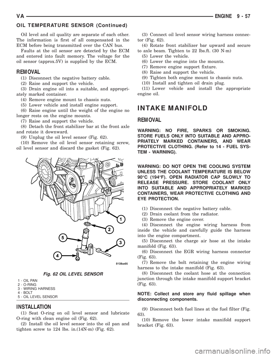
(9) Unplug the oil level sensor (Fig. 62).
(10) Remove the oil level sensor retaining screw,
oil level sensor and discard the gasket (Fig. 62).
INSTALLATION
(1) Seat O-ring on oil level sensor and lubricate
O-ring with clean engine oil (Fig. 62).
(2) Install the oil level sensor into the oil pan and
tighten screw to 124 lbs. in.(14N´m) (Fig. 62).(3) Connect oil level sensor wiring harness connec-
tor (Fig. 62).
(4) Rotate front stabilizer bar upward and secure
to axle beam. Tighten to 22 lbs.ft. (30 N´m)
(5) Lower the vehicle.
(6) Lower the engine into the mounts.
(7) Remove engine support fixture.
(8) Raise and support the vehicle.
(9) Tighten both engine mount to chassis nuts.
(10) Install and tighten oil drain plug.
(11) Lower vehicle and install the appropriate
engine oil.
INTAKE MANIFOLD
REMOVAL
WARNING: NO FIRE, SPARKS OR SMOKING.
STORE FUELS ONLY INTO SUITABLE AND APPRO-
PRIATELY MARKED CONTAINERS, AND WEAR
PROTECTIVE CLOTHING. (Refer to 14 - FUEL SYS-
TEM - WARNING).
WARNING: DO NOT OPEN THE COOLING SYSTEM
UNLESS THE COOLANT TEMPERATURE IS BELOW
90ÉC (194ÉF). OPEN RADIATOR CAP SLOWLY TO
RELEASE PRESSURE. STORE COOLANT ONLY
INTO SUITABLE AND APPROPRIATELY MARKED
CONTAINERS, WEAR PROTECTIVE CLOTHING AND
EYE PROTECTION.
(1) Disconnect the negative battery cable.
(2) Drain coolant from the radiator.
(3) Remove the engine cover.
(4) Disconnect the engine wiring harness from
inside the vehicle and carefully guide the harness
into the engine compartment.
(5) Disconnect the charge air hose at the intake
manifold (Fig. 63).
(6) Disconnect the EGR wiring harness connector
(Fig. 63).
(7) Remove the bolt retaining the engine wiring
harness to the intake manifold (Fig. 63).
(8) Disconnect the coolant hose at the connection
junction through the intake manifold support bracket
(Fig. 63).
NOTE: Collect and store any fluid spillage when
disconnecting components.
(9) Disconnect both fuel lines at the fuel filter (Fig.
63).
(10) Remove the lower intake manifold support
bracket (Fig. 63).
Fig. 62 OIL LEVEL SENSOR
1 - OIL PAN
2 - O-RING
3 - WIRING HARNESS
4 - BOLT
5 - OIL LEVEL SENSOR
VAENGINE 9 - 57
OIL TEMPERATURE SENSOR (Continued)
Page 797 of 1232
(7) Install the right intake manifold support brack-
ets. Tighten the bolts to 14 N´m (124 lbs. in.) (Fig.
63).
(8) Install the lower intake manifold support
bracket. Tighten bolts to 20 N´m (177 lbs. in.) (Fig.
63).
(9) Connect both fuel lines to fuel filter assembly
(Refer to 14 - FUEL SYSTEM/FUEL DELIVERY/
FUEL FILTER - INSTALLATION).
(10) Connect the coolant hose at the connection
junction above the lower intake manifold support
bracket (Fig. 63).
(11) Secure the engine wiring harness and cable
duct to the intake manifold (Fig. 63).
(12) Connect the EGR wiring harness connector
(Fig. 63).
(13) Connect the charge air hose to the intake
manifold (Fig. 63).
(14) Carefully route the engine wiring harness
through and into the passenger compartment and
reconnect.
(15) Install the engine cover.
(16) Fill the cooling system.
(17) Connect the negative battery cable.
(18) Start the engine and inspect for leaks. Care
must be taken to observe the fuel system warnin-
g.(Refer to 14 - FUEL SYSTEM - WARNING).
EXHAUST MANIFOLD
REMOVAL
(1) Remove the turbocharger (Refer to 11 -
EXHAUST SYSTEM/TURBOCHARGER SYSTEM/
TURBOCHARGER - REMOVAL).
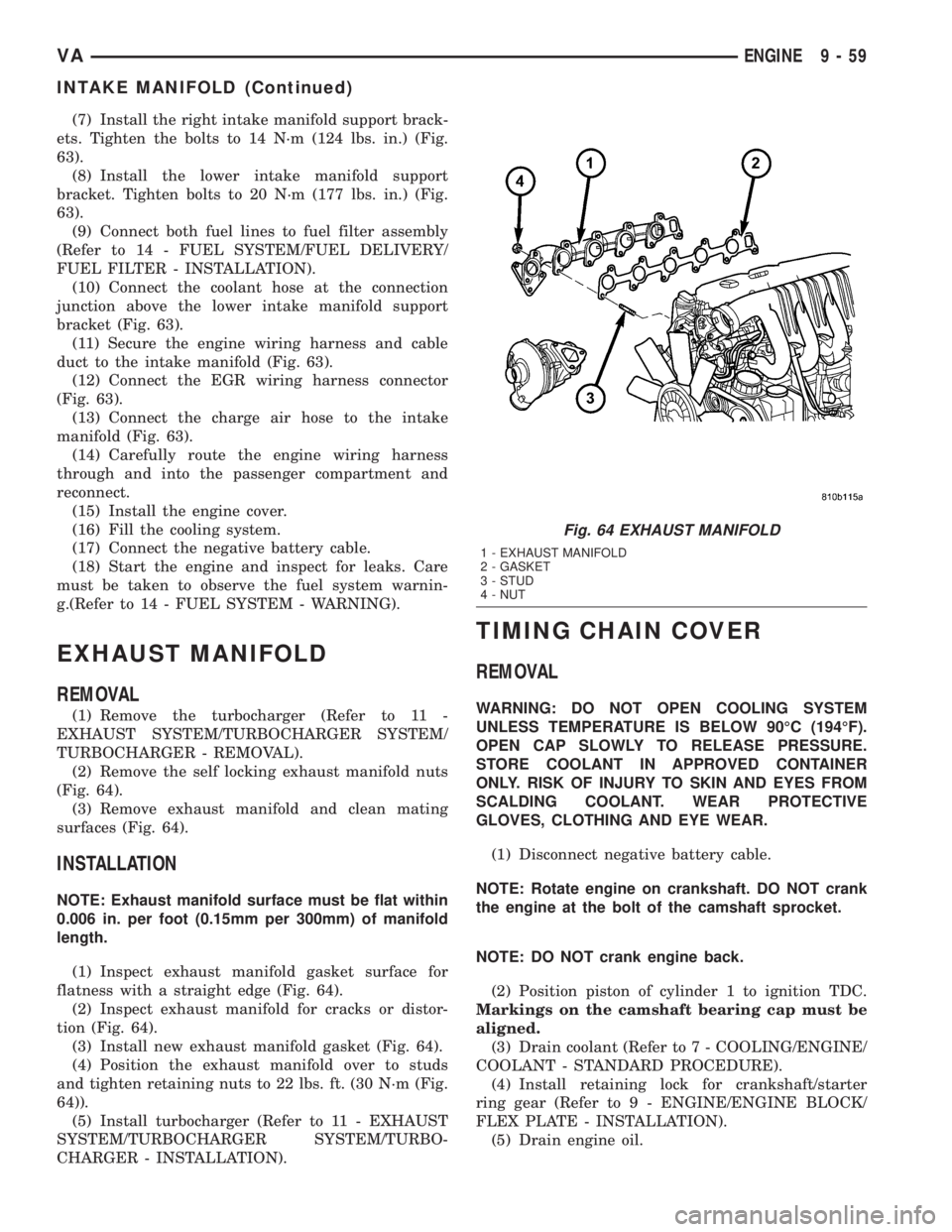
(2) Remove the self locking exhaust manifold nuts
(Fig. 64).
(3) Remove exhaust manifold and clean mating
surfaces (Fig. 64).
INSTALLATION
NOTE: Exhaust manifold surface must be flat within
0.006 in. per foot (0.15mm per 300mm) of manifold
length.
(1) Inspect exhaust manifold gasket surface for
flatness with a straight edge (Fig. 64).
(2) Inspect exhaust manifold for cracks or distor-
tion (Fig. 64).
(3) Install new exhaust manifold gasket (Fig. 64).
(4) Position the exhaust manifold over to studs
and tighten retaining nuts to 22 lbs. ft. (30 N´m (Fig.
64)).
(5) Install turbocharger (Refer to 11 - EXHAUST
SYSTEM/TURBOCHARGER SYSTEM/TURBO-
CHARGER - INSTALLATION).
TIMING CHAIN COVER
REMOVAL
WARNING: DO NOT OPEN COOLING SYSTEM
UNLESS TEMPERATURE IS BELOW 90ÉC (194ÉF).
OPEN CAP SLOWLY TO RELEASE PRESSURE.
STORE COOLANT IN APPROVED CONTAINER
ONLY. RISK OF INJURY TO SKIN AND EYES FROM
SCALDING COOLANT. WEAR PROTECTIVE
GLOVES, CLOTHING AND EYE WEAR.
(1) Disconnect negative battery cable.
NOTE: Rotate engine on crankshaft. DO NOT crank
the engine at the bolt of the camshaft sprocket.
NOTE: DO NOT crank engine back.
(2) Position piston of cylinder 1 to ignition TDC.
Markings on the camshaft bearing cap must be
aligned.
(3) Drain coolant (Refer to 7 - COOLING/ENGINE/
COOLANT - STANDARD PROCEDURE).
(4) Install retaining lock for crankshaft/starter
ring gear (Refer to 9 - ENGINE/ENGINE BLOCK/
FLEX PLATE - INSTALLATION).
(5) Drain engine oil.
Fig. 64 EXHAUST MANIFOLD
1 - EXHAUST MANIFOLD
2 - GASKET
3 - STUD
4 - NUT
VAENGINE 9 - 59
INTAKE MANIFOLD (Continued)
Page 799 of 1232
(8) Position and install the oil pan. Tighten M6
bolts to 9 N´m (80 lbs in) and M8 bolts to 20 N´m
(177 lbs in).
(9) Install belt /pulley vibration damper. Tighten
M8.8 bolt in two stages, 200N´m (147 lbs ft.) then
90É, M10.9 bolt 325N´m (240 lbs ft) then 90É.
(10) Remove the engine support fixture.
(11) Install generator (Refer to 8 - ELECTRICAL/
CHARGING/GENERATOR - INSTALLATION).
(12) Install the air conditioning compressor.
(13) Install the power steering pump.
(14) Install water pump (Refer to 7 - COOLING/
ENGINE/WATER PUMP - INSTALLATION).
(15) Connect coolant hose to oil-water heat
exchanger.
(16) Install high pressure fuel pump (Refer to 14 -
FUEL SYSTEM/FUEL DELIVERY/FUEL PUMP -
INSTALLATION).
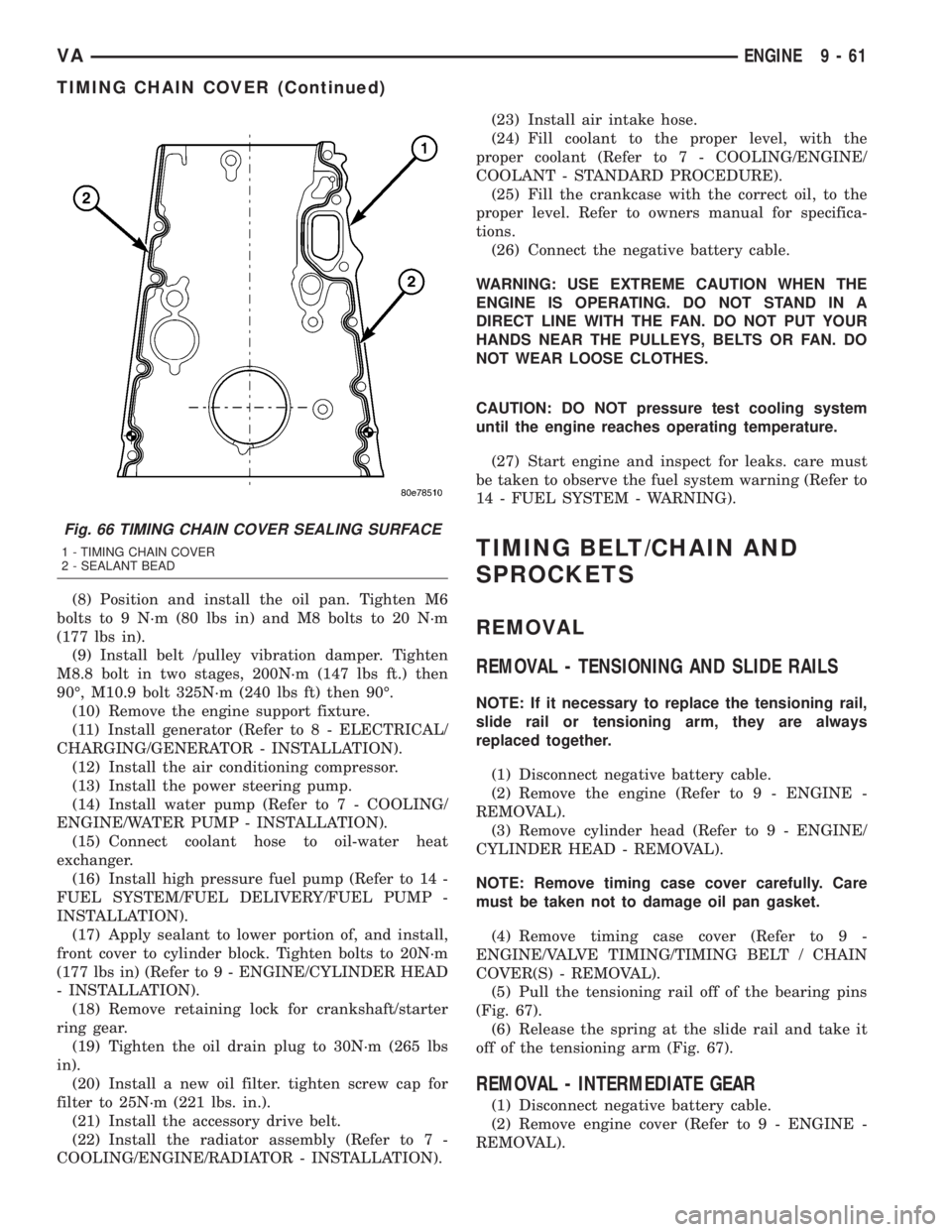
(17) Apply sealant to lower portion of, and install,
front cover to cylinder block. Tighten bolts to 20N´m
(177 lbs in) (Refer to 9 - ENGINE/CYLINDER HEAD
- INSTALLATION).
(18) Remove retaining lock for crankshaft/starter
ring gear.
(19) Tighten the oil drain plug to 30N´m (265 lbs
in).
(20) Install a new oil filter. tighten screw cap for
filter to 25N´m (221 lbs. in.).
(21) Install the accessory drive belt.
(22) Install the radiator assembly (Refer to 7 -
COOLING/ENGINE/RADIATOR - INSTALLATION).(23) Install air intake hose.
(24) Fill coolant to the proper level, with the
proper coolant (Refer to 7 - COOLING/ENGINE/
COOLANT - STANDARD PROCEDURE).
(25) Fill the crankcase with the correct oil, to the
proper level. Refer to owners manual for specifica-
tions.
(26) Connect the negative battery cable.
WARNING: USE EXTREME CAUTION WHEN THE
ENGINE IS OPERATING. DO NOT STAND IN A
DIRECT LINE WITH THE FAN. DO NOT PUT YOUR
HANDS NEAR THE PULLEYS, BELTS OR FAN. DO
NOT WEAR LOOSE CLOTHES.
CAUTION: DO NOT pressure test cooling system
until the engine reaches operating temperature.
(27) Start engine and inspect for leaks. care must
be taken to observe the fuel system warning (Refer to
14 - FUEL SYSTEM - WARNING).
TIMING BELT/CHAIN AND
SPROCKETS
REMOVAL
REMOVAL - TENSIONING AND SLIDE RAILS
NOTE: If it necessary to replace the tensioning rail,
slide rail or tensioning arm, they are always
replaced together.
(1) Disconnect negative battery cable.
(2) Remove the engine (Refer to 9 - ENGINE -
REMOVAL).
(3) Remove cylinder head (Refer to 9 - ENGINE/
CYLINDER HEAD - REMOVAL).
NOTE: Remove timing case cover carefully. Care
must be taken not to damage oil pan gasket.
(4) Remove timing case cover (Refer to 9 -
ENGINE/VALVE TIMING/TIMING BELT / CHAIN
COVER(S) - REMOVAL).
(5) Pull the tensioning rail off of the bearing pins
(Fig. 67).
(6) Release the spring at the slide rail and take it
off of the tensioning arm (Fig. 67).
REMOVAL - INTERMEDIATE GEAR
(1) Disconnect negative battery cable.
(2) Remove engine cover (Refer to 9 - ENGINE -
REMOVAL).
Fig. 66 TIMING CHAIN COVER SEALING SURFACE
1 - TIMING CHAIN COVER
2 - SEALANT BEAD
VAENGINE 9 - 61
TIMING CHAIN COVER (Continued)
Page 839 of 1232
INSTALLATION - LOW PRESSURE PUMP
WARNING: NO SPARKS, OPEN FLAMES OR SMOK-
ING. RISK OF POISONING FROM INHALING AND
SWALLOWING FUEL. RISK OF INJURY TO EYES
AND SKIN FROM CONTACT WITH FUEL. POUR
FUELS ONLY INTO SUITABLE AND APPROPRI-
ATELY MARKED CONTAINERS. WEAR PROTECTIVE
CLOTHING.
NOTE: Clean sealing surfaces, replace seal if nec-
essary.
(1) Prime the low pressure pump with the appro-
priate fuel.
(2) Attach low pressure fuel pump to cylinder head
front cover. Tighten bolt to 9N´m (80 lbs. in.).
(3) Attach fuel lines to low pressure pump.
(4) Install vacuum pump (Refer to 9 - ENGINE/
ENGINE BLOCK/INTERNAL VACUUM PUMP -
INSTALLATION).
(5) Reconnect negative battery cable.
WARNING: USE EXTREME CAUTION WHEN THE
ENGINE IS OPERATING. DO NOT STAND IN A
DIRECT LINE WITH FAN. DO NOT PUT YOUR
HANDS NEAR PULLEYS, BELTS OR FAN. DO NOT
WEAR LOOSE CLOTHING.
(6) Start engine and inspect for leaks.
FUEL RAIL
DESCRIPTION
The fuel rail acts like a high pressure store. It is
available to all injectors for drawing fuel which has
been compressed by the injection pump. The rail
pressure sensor, rail pressure solenoid, high pressure
line, and the return flow line are attached to the fuel
rail (Fig. 7).
OPERATION
The stored fuel volume inside the rail acts as a
damper for pressure fluctuations which result
because of pulsating supply and brief large extrac-
tions of fuel during injector firing. The rail primarily
influences the atomization of fuel at the injector noz-
zle, and the accuracy of injected quantity during
injection.
REMOVAL
(Refer to 14 - FUEL SYSTEM - WARNING).
WARNING: NO SPARKS, OPEN FLAMES OR SMOK-
ING. RISK OF POISONING FROM INHALING AND
SWALLOWING FUEL. RISK OF INJURY TO EYES
AND SKIN FROM CONTACT WITH FUEL. POUR
FUELS ONLY INTO SUITABLE AND APPROPRI-
ATELY MARKED CONTAINERS. WEAR PROTECTIVE
CLOTHING.
(1) Disconnect negative battery cable.
(2) Partially drain cooling system from radiator
only.
(3) Remove thermostat housing.
(4) Disconnect engine wiring electrical connectors
from sensors restricting harness movement.
(5) Remove engine harness retaining bolts.
(6) Remove fuel temperature sensor from fuel rail.
(7) Remove fuel rail retaining bolts and disconnect
glow plug connectors.
(8) Remove front engine lift support.
CAUTION: When slackening and tightening fuel
injection line union nuts, counter hold with wrench
at threaded connection. ON NO ACCOUNT exceed
the tightening torque at any time. Do NOT crimp or
bend lines.
NOTE: After removing lines, seal connections and
ensure cleanliness.
(9) Remove injector high pressure lines (Refer to
14 - FUEL SYSTEM/FUEL DELIVERY/FUEL LINES
- REMOVAL) (Fig. 7).
(10) Remove pressure line of high pressure pump
(Fig. 7).
(11) Detach fuel return flow line to high pressure
pump at rail (Fig. 7).
(12) Detach fuel return flow line to fuel filter at
fuel filter (Fig. 7).
(13) Remove fuel rail (Fig. 7).
INSTALLATION
(Refer to 14 - FUEL SYSTEM - WARNING)
WARNING: NO FIRE, FLAMES OR SMOKING. RISK
OF POISONING FROM INHALING OR SWALLOWING
FUEL. RISK OF INJURY TO EYES AND SKIN FROM
CONTACT WITH FUEL. POUR FUELS ONLY INTO
SUITABLE AND APPROPRIATELY MARKED CON-
TAINERS. WEAR PROTECTIVE CLOTHING.
VAFUEL DELIVERY 14 - 11
FUEL PUMP (Continued)
Page 840 of 1232
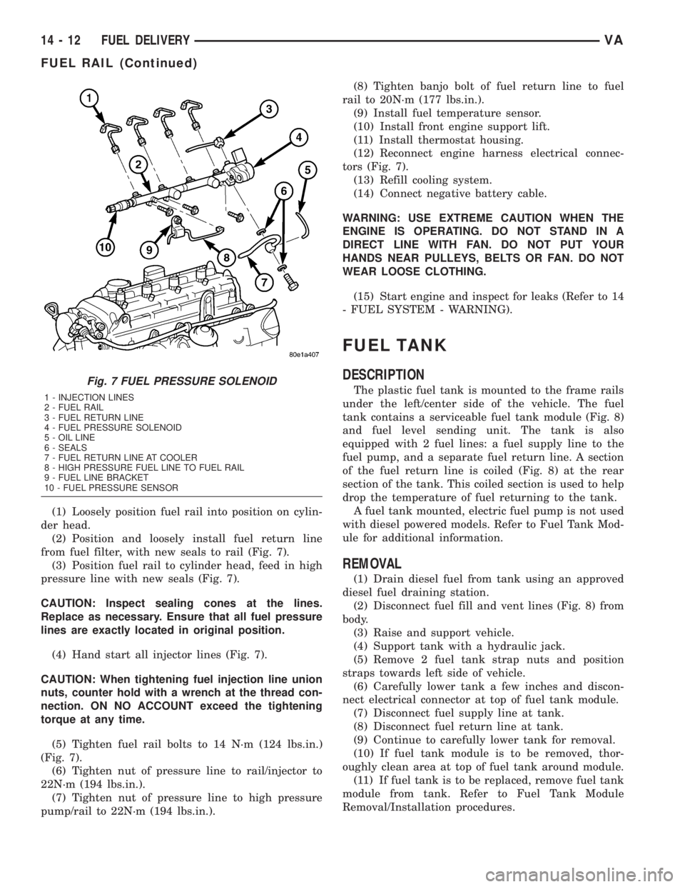
(1) Loosely position fuel rail into position on cylin-
der head.
(2) Position and loosely install fuel return line
from fuel filter, with new seals to rail (Fig. 7).
(3) Position fuel rail to cylinder head, feed in high
pressure line with new seals (Fig. 7).
CAUTION: Inspect sealing cones at the lines.
Replace as necessary. Ensure that all fuel pressure
lines are exactly located in original position.
(4) Hand start all injector lines (Fig. 7).
CAUTION: When tightening fuel injection line union
nuts, counter hold with a wrench at the thread con-
nection. ON NO ACCOUNT exceed the tightening
torque at any time.
(5) Tighten fuel rail bolts to 14 N´m (124 lbs.in.)
(Fig. 7).
(6) Tighten nut of pressure line to rail/injector to
22N´m (194 lbs.in.).
(7) Tighten nut of pressure line to high pressure
pump/rail to 22N´m (194 lbs.in.).(8) Tighten banjo bolt of fuel return line to fuel
rail to 20N´m (177 lbs.in.).
(9) Install fuel temperature sensor.
(10) Install front engine support lift.
(11) Install thermostat housing.
(12) Reconnect engine harness electrical connec-
tors (Fig. 7).
(13) Refill cooling system.
(14) Connect negative battery cable.
WARNING: USE EXTREME CAUTION WHEN THE
ENGINE IS OPERATING. DO NOT STAND IN A
DIRECT LINE WITH FAN. DO NOT PUT YOUR
HANDS NEAR PULLEYS, BELTS OR FAN. DO NOT
WEAR LOOSE CLOTHING.
(15) Start engine and inspect for leaks (Refer to 14
- FUEL SYSTEM - WARNING).
FUEL TANK
DESCRIPTION
The plastic fuel tank is mounted to the frame rails
under the left/center side of the vehicle. The fuel
tank contains a serviceable fuel tank module (Fig. 8)
and fuel level sending unit. The tank is also
equipped with 2 fuel lines: a fuel supply line to the
fuel pump, and a separate fuel return line. A section
of the fuel return line is coiled (Fig. 8) at the rear
section of the tank. This coiled section is used to help
drop the temperature of fuel returning to the tank.
A fuel tank mounted, electric fuel pump is not used
with diesel powered models. Refer to Fuel Tank Mod-
ule for additional information.
REMOVAL
(1) Drain diesel fuel from tank using an approved
diesel fuel draining station.
(2) Disconnect fuel fill and vent lines (Fig. 8) from
body.
(3) Raise and support vehicle.
(4) Support tank with a hydraulic jack.
(5) Remove 2 fuel tank strap nuts and position
straps towards left side of vehicle.
(6) Carefully lower tank a few inches and discon-
nect electrical connector at top of fuel tank module.
(7) Disconnect fuel supply line at tank.
(8) Disconnect fuel return line at tank.
(9) Continue to carefully lower tank for removal.
(10) If fuel tank module is to be removed, thor-
oughly clean area at top of fuel tank around module.
(11) If fuel tank is to be replaced, remove fuel tank
module from tank. Refer to Fuel Tank Module
Removal/Installation procedures.
Fig. 7 FUEL PRESSURE SOLENOID
1 - INJECTION LINES
2 - FUEL RAIL
3 - FUEL RETURN LINE
4 - FUEL PRESSURE SOLENOID
5 - OIL LINE
6 - SEALS
7 - FUEL RETURN LINE AT COOLER
8 - HIGH PRESSURE FUEL LINE TO FUEL RAIL
9 - FUEL LINE BRACKET
10 - FUEL PRESSURE SENSOR
14 - 12 FUEL DELIVERYVA
FUEL RAIL (Continued)
Page 851 of 1232
NOTE: Always replace the seals that seal off the
injectors at the cylinder head to the combustion
chamber and replace the retaining screws.
REMOVAL
WARNING: HIGH-PRESSURE FUEL LINES DELIVER
DIESEL FUEL UNDER EXTREME PRESSURE FROM
THE INJECTION PUMP TO THE FUEL INJECTORS.
THIS MAY BE AS HIGH AS 1600BAR (23,200 PSI).
USE EXTREME CAUTION WHEN INSPECTING FOR
HIGH-PRESSURE FUEL LEAKS. FUEL UNDER THIS
AMOUNT OF PRESSURE CAN PENETRATE SKIN
CAUSING PERSONAL INJURY OR DEATH. INSPECT
FOR HIGH-PRESSURE LEAKS WITH A SHEET OF
CARD BOARD. WEAR SAFETY GOGGLES AND
ADEQUATE PROTECTIVE CLOTHING WHEN SER-
VICING FUEL SYSTEM.
WARNING: NO SPARKS, OPEN FLAMES OR SMOK-
ING. RISK OF POISONING FROM INHALING AND
SWALLOWING FUEL. RISK OF INJURY TO EYES
AND SKIN FROM CONTACT WITH FUEL. POUR
FUELS ONLY INTO SUITABLE AND APPROPRI-
ATELY MARKED CONTAINERS. WEAR PROTECTIVE
CLOTHING.
NOTE: The engine must be lowered in the vehicle to
remove the fourth and fifth cylinders fuel injectors.
(1) Disconnect negative battery cable.
(2) Remove engine cover (Refer to 9 - ENGINE -
REMOVAL).
(3) Raise and suitably support the vehicle.
(4) Remove lower radiator deflector plate.
(5) Drain cooling system (Refer to 7 - COOLING/
ENGINE/COOLANT - STANDARD PROCEDURE).
(6) Remove turbocharger down pipe assembly.
(7) Remove oil dipstick tube retaining bolt and pull
tube from oil pan.
(8) Lower vehicle.
(9) Remove upper radiator hose.
(10) Remove air cleaner box assembly and hoses.
(11) Remove charge air cooler inlet hose.
(12) Remove charge air cooler to turbocharger inlet
adaptor.
(13) Remove turbocharger to right engine mount
bracket.
(14) Disconnect steering coupler at gear box (RHD
Only).
(15) Remove battery (Refer to 8 - ELECTRICAL/
BATTERY SYSTEM/BATTERY - REMOVAL).
(16) Unclip PDC from battery tray and set aside.(17) Remove battery tray (Refer to 8 - ELECTRI-
CAL/BATTERY SYSTEM/TRAY - REMOVAL).
(18) Remove power steering reservoir (Refer to 19 -
STEERING/PUMP/RESERVOIR - REMOVAL).
(19) Remove charger air cooler outlet hose.
(20) Remove intake manifold to left engine mount
bracket.
(21) Evacuate air conditioning system (Refer to 24
- HEATING & AIR CONDITIONING/PLUMBING -
STANDARD PROCEDURE).
(22) Disconnect air conditioning suction / discharge
lines at A/C compressor.
(23) Disconnect pedal position sensor electrical
connector.
(24) Unplug injector electrical connectors.
(25) Remove fuel / water separator to intake man-
ifold retaining bolts.
(26) Support engine with hoist.
(27) Remove engine mount through bolts.
(28) Remove right engine mount sill plate.
NOTE: Counterhold injection lines with wrench
socket at threaded connections of injectors.
(29) Disconnect fuel injector high pressure line.
(30) Remove fuel injector retaining bolt and ten-
sion claw.
(31) Suitably lower engine to gain fuel injector
access and remove injector.
NOTE: If injectors are tight, remove with extraction
claw in place of tensioning claw. If extraction claw
contacts cylinder head cover, remove cylinder head
cover. If necessary, remove injectors with threaded
adaptor and discard injector.
(32) Remove injectors (Fig. 10).
(33) Clean injectors and recesses (Refer to 14 -
FUEL SYSTEM/FUEL INJECTION/FUEL INJEC-
TOR - STANDARD PROCEDURE).
INSTALLATION
WARNING: HIGH-PRESSURE FUEL LINES DELIVER
DIESEL FUEL UNDER EXTREME PRESSURE FROM
THE INJECTION PUMP TO THE FUEL INJECTORS.
THIS MAY BE AS HIGH AS 1600BAR (23,200 PSI).
USE EXTREME CAUTION WHEN INSPECTING FOR
HIGH-PRESSURE FUEL LEAKS. FUEL UNDER THIS
AMOUNT OF PRESSURE CAN PENETRATE SKIN
CAUSING PERSONAL INJURY OR DEATH. INSPECT
FOR HIGH-PRESSURE LEAKS WITH A SHEET OF
CARD BOARD. WEAR SAFETY GOGGLES AND
ADEQUATE PROTECTIVE CLOTHING WHEN SER-
VICING FUEL SYSTEM.
VAFUEL INJECTION 14 - 23
FUEL INJECTOR (Continued)
Page 853 of 1232
(15) Install battery tray(Refer to 8 - ELECTRI-
CAL/BATTERY SYSTEM/TRAY - INSTALLATION).
(16) Connect PDC to battery tray.
(17) Install battery (Refer to 8 - ELECTRICAL/
BATTERY SYSTEM/BATTERY - INSTALLATION).
(18) Connect steering coupler at gear box (RHD
Only).
(19) Install turbocharger to right engine mount
bracket (Refer to 11 - EXHAUST SYSTEM/TURBO-
CHARGER SYSTEM - INSTALLATION).
(20) Install charge air cooler to turbocharger inlet
adaptor (Refer to 11 - EXHAUST SYSTEM/CHARGE
AIR COOLER AND PLUMBING - INSTALLATION) .
(21) Install charger air cooler inlet hose (Refer to
11 - EXHAUST SYSTEM/CHARGE AIR COOLER
AND PLUMBING - INSTALLATION).
(22) Install air cleaner box assembly and hoses.
(23) Install upper radiator hose.
(24) Raise vehicle.
(25) Install dipstick tube into oil pan and tighten
retaining bolt.
(26) Install turbocharger down pipe assembly.
(27) Close cooling system drain.
(28) Install lower radiator deflector plate.
(29) Lower vehicle.
(30) Connect negative battery cable.
(31) Install engine cover (Refer to 9 - ENGINE -
INSTALLATION)..
(32) Fill cooling system with the correct mixture to
the proper level (Refer to 7 - COOLING/ENGINE/
COOLANT - STANDARD PROCEDURE).
WARNING: USE EXTREME CAUTION WHEN THE
ENGINE IS OPERATING. DO NOT PUT YOUR
HANDS NEAR PULLEYS, BELTS OR FAN. DO NOT
WEAR LOOSE CLOTHING.
(33) Start engine and inspect for leaks.
(34) Recharge air conditioning system.
FUEL PRESSURE SENSOR
DESCRIPTION
DESCRIPTION
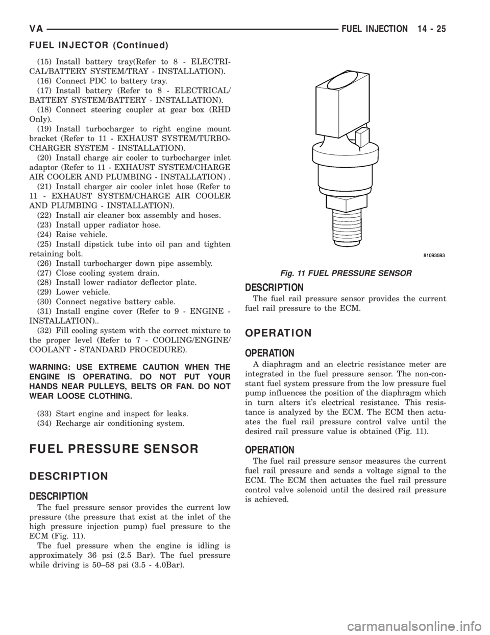
The fuel pressure sensor provides the current low
pressure (the pressure that exist at the inlet of the
high pressure injection pump) fuel pressure to the
ECM (Fig. 11).
The fuel pressure when the engine is idling is
approximately 36 psi (2.5 Bar). The fuel pressure
while driving is 50±58 psi (3.5 - 4.0Bar).
DESCRIPTION
The fuel rail pressure sensor provides the current
fuel rail pressure to the ECM.
OPERATION
OPERATION
A diaphragm and an electric resistance meter are
integrated in the fuel pressure sensor. The non-con-
stant fuel system pressure from the low pressure fuel
pump influences the position of the diaphragm which
in turn alters it's electrical resistance. This resis-
tance is analyzed by the ECM. The ECM then actu-
ates the fuel rail pressure control valve until the
desired rail pressure value is obtained (Fig. 11).
OPERATION
The fuel rail pressure sensor measures the current
fuel rail pressure and sends a voltage signal to the
ECM. The ECM then actuates the fuel rail pressure
control valve solenoid until the desired rail pressure
is achieved.
Fig. 11 FUEL PRESSURE SENSOR
VAFUEL INJECTION 14 - 25
FUEL INJECTOR (Continued)
Page 873 of 1232
Wipe filler cap clean, then check the fluid level.
The dipstick should indicateCOLDwhen the fluid is
at normal temperature.
(1) Turn steering wheel all the way to the left
(2) Fill the pump fluid reservoir to the proper level
and let the fluid settle for at least two (2) minutes.
(3) Raise the front wheels off the ground.
(4)
Slowly turn the steering wheel lock-to-lock 20
times with the engine off while checking the fluid level.
NOTE: For vehicles with long return lines or oil
coolers turn wheel 40 times.
(5) Start the engine. With the engine idling main-
tain the fluid level.
(6) Lower the front wheels and let the engine idle
for two minutes.
(7) Turn the steering wheel in both direction and
verify power assist and quiet operation of the pump.
If the fluid is extremely foamy or milky looking,
allow the vehicle to stand a few minutes and repeat
the procedure.
CAUTION: Do not run a vehicle with foamy fluid for
an extended period. This may cause pump damage.
STANDARD PROCEDURE - FLUSHING POWER
STEERING SYSTEM
Flushing is required when the power steering/hy-
draulic booster system fluid has become contami-
nated. Contaminated fluid in the steering/booster
system can cause seal deterioration and affect steer-
ing gear/booster spool valve operation.
(1) Raise the front end of the vehicle off the
ground until the wheels are free to turn.
(2) Remove the return line from the pump.
NOTE: If vehicle is equipped with a hydraulic
booster remove both return lines from the pump.
(3) Plug the return line port/ports at the pump.
(4) Position the return line/lines into a large con-
tainer to catch the fluid.
(5) While an assistant is filling the pump reservoir
start the engine.
(6) With the engine running at idle turn the wheel
back and forth.
NOTE: Do not contact or hold the wheel against the
steering stops.
(7) Run a quart of fluid through the system then
stop the engine and install the return line/lines.
(8) Fill the system with fluid and perform Steering
Pump Initial Operation, (Refer to 19 - STEERING/
PUMP - STANDARD PROCEDURE).(9) Start the engine and run it for fifteen minutes
then stop the engine.
(10) Remove the return line/lines from the pump
and plug the pump port/ports.
(11) Pour fresh fluid into the reservoir and check
the draining fluid for contamination. If the fluid is
still contaminated, then flush the system again.
(12) Install the return line/lines and perform
Steering Pump Initial Operation, (Refer to 19 -
STEERING/PUMP - STANDARD PROCEDURE).
REMOVAL
(1) Remove the belt from the power steering pump.
(2) Siphon as much power steering fluid as possi-
ble out of the reservoir.
(3) Remove the high pressure power steering hose
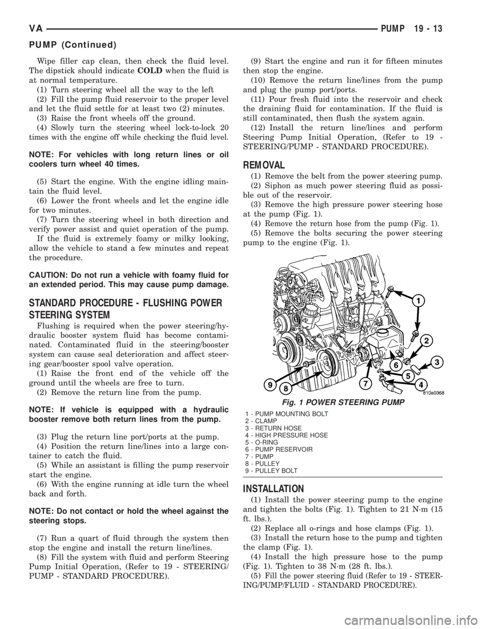
at the pump (Fig. 1).
(4)
Remove the return hose from the pump (Fig. 1).
(5) Remove the bolts securing the power steering
pump to the engine (Fig. 1).
INSTALLATION
(1) Install the power steering pump to the engine
and tighten the bolts (Fig. 1). Tighten to 21 N´m (15
ft. lbs.).
(2) Replace all o-rings and hose clamps (Fig. 1).
(3) Install the return hose to the pump and tighten
the clamp (Fig. 1).
(4) Install the high pressure hose to the pump
(Fig. 1). Tighten to 38 N´m (28 ft. lbs.).
(5)
Fill the power steering fluid (Refer to 19 - STEER-
ING/PUMP/FLUID - STANDARD PROCEDURE).
Fig. 1 POWER STEERING PUMP
1 - PUMP MOUNTING BOLT
2 - CLAMP
3 - RETURN HOSE
4 - HIGH PRESSURE HOSE
5 - O-RING
6 - PUMP RESERVOIR
7 - PUMP
8 - PULLEY
9 - PULLEY BOLT
VAPUMP 19 - 13
PUMP (Continued)