2005 MERCEDES-BENZ SPRINTER cooling
[x] Cancel search: coolingPage 185 of 1232
ENGINE TEMPERATURE
GAUGE
DESCRIPTION
An engine coolant temperature gauge is standard
equipment on all instrument clusters. The engine
coolant temperature gauge is located in the upper
right corner of the instrument cluster, to the right of
the speedometer. The engine coolant temperature
gauge consists of a movable gauge needle or pointer
controlled by the instrument cluster circuitry and a
fixed 45 degree scale on the cluster overlay that
reads left-to-right from 120É C to 40É C for Canadian
vehicles, or from 250É F to 110É F for United States
vehicles. An International Control and Display Sym-
bol icon for ªEngine Coolant Temperatureº is located
on the cluster overlay, directly below the high end of
the scale. Just to the right of the icon, the nomencla-
ture ªÉCº or ªÉFº confirms the unit of measure for the
gauge readings.
The engine coolant temperature gauge graphics are
white against a black field, except for a single red
graduation at the far left (high) end of the gauge
scale, making them clearly visible within the instru-
ment cluster in daylight. When illuminated from
behind by the panel lamps dimmer controlled cluster
illumination lighting with the exterior lamps turned
On, the white graphics appear amber and the red
graphics appear red. The orange gauge needle is
internally illuminated. Gauge illumination is pro-
vided by Light Emitting Diode (LED) units soldered
onto the instrument cluster electronic circuit board.
The engine coolant temperature gauge is serviced as
a unit with the instrument cluster.
OPERATION
The engine coolant temperature gauge gives an
indication to the vehicle operator of the engine cool-
ant temperature. This gauge is controlled by the
instrument cluster circuit board based upon cluster
programming and electronic messages received by
the cluster from the Engine Control Module (ECM)
over the Controller Area Network (CAN) data bus.
The engine coolant temperature gauge is an air core
magnetic unit that receives battery current on the
instrument cluster electronic circuit board when the
instrument cluster detects that the ignition switch is
in the On position. The cluster is programmed to
move the gauge needle back to the low end of the
scale after the ignition switch is turned to the Off
position. The instrument cluster circuitry controls
the gauge needle position and provides the following
features:
²Engine Temperature Normal Message- Each
time the cluster receives a message from the ECMindicating the engine coolant temperature is within
the normal operating range [up to about 120É C (250É
F), the gauge needle is moved to the actual relative
temperature position on the gauge scale.
²Engine Temperature High Message- Each
time the cluster receives a message from the ECM
indicating the engine coolant temperature is high
[above about 120É C (250É F) the gauge needle is
moved into the red warning zone on the gauge scale.
The ECM continually monitors the engine coolant
temperature sensor to determine the engine operat-
ing temperature. The ECM then sends the proper
engine coolant temperature messages to the instru-
ment cluster. If the instrument cluster moves the
engine coolant temperature gauge needle to red area
of the gauge scale, it may indicate that the engine or
the engine cooling system require service. For proper
diagnosis of the engine coolant temperature sensor,
the ECM, the CAN data bus, the electronic message
inputs to the instrument cluster, or the instrument
cluster circuitry that controls the engine coolant tem-
perature gauge, a DRBIIItscan tool is required.
Refer to the appropriate diagnostic information.
FUEL FILTER CLOGGED
INDICATOR
DESCRIPTION
A fuel filter clogged indicator is standard equip-
ment on all instrument clusters. The fuel filter
clogged indicator is located near the left edge of the
instrument cluster, next to the tachometer. The fuel
filter clogged indicator consists of the International
Control and Display Symbol icon for ªFuel Filterº
imprinted within a rectangular cutout in the opaque
layer of the instrument cluster overlay. The dark
outer layer of the overlay prevents the indicator from
being clearly visible when it is not illuminated. An
amber Light Emitting Diode (LED) behind the cutout
in the opaque layer of the overlay causes the icon to
appear silhouetted against an amber field through
the translucent outer layer of the overlay when the
indicator is illuminated from behind by the LED,
which is soldered onto the instrument cluster elec-
tronic circuit board. The fuel filter clogged indicator
is serviced as a unit with the instrument cluster.
OPERATION
The fuel filter clogged indicator gives an indication
to the vehicle operator when the pressure in the fuel
system is low, which could indicate that the fuel filter
is clogged. This indicator is controlled by a transistor
on the instrument cluster circuit board based upon
cluster programming and electronic messages
received by the cluster from the Engine Control Mod-
VAINSTRUMENT CLUSTER 8J - 15
Page 741 of 1232
DESCRIPTION SPECIFICATION
Engine 2.7L CDI
Engine Description 5 Cylinder In-Line Engine
With 4-Valve Technology
Air Intake Turbo-Charged Engine
with Charge Air Cooling
Fuel Injection System Common Rail Diesel
Injection (CDI)
Fuel Diesel
Firing Order 1-2-4-5-3
Rated Output 125/4200 kW at RPM
Torque 400/1600-2400 Nm at
RPM
Maximum Speed 4800 RPM
Compression Ratio 19:1
Bore/Stroke 88.0/88.4 mm
Eff. Displacement 2688 cm3
STANDARD PROCEDURE
STANDARD PROCEDURE - COMPRESSION
TESTING ENGINE
(1) Warm up engine to operating temperature
(approx. 80 ÉC, 176ÉF).
(2) Shut off engine.
(3) Remove engine cover (Refer to 9 - ENGINE -
REMOVAL).
(4) Remove glow plugs (Refer to 8 - ELECTRICAL/
IGNITION CONTROL/GLOW PLUG - REMOVAL).
(5) Crank engine several times with the starter to
eliminate combustion residues in the cylinders.
(6) Insert compression tester adapter #8927 (Refer
to 9 - ENGINE - SPECIAL TOOLS) with check valve
installed into glow plug hole of cylinder to be tested.
(7) Connect compression tester hose adapter #9295
to compression gauge and test compression pressure
by cranking engine with starter for at least 8 revolu-
tions.
(8) Carry out test procedure at the remaining cyl-
inders in the same way.
(9) Compare pressure readings obtained with the
specified pressures. If the pressure reading is below
the minimum compression pressure or if the permis-
sible difference between the individual cylinders is
exceeded. Refer to cylinder leak down test.
(10) Remove compression tester and adapter from
cylinder head.
(11)
Install glow plugs (Refer to 8 - ELECTRICAL/IG-
NITION CONTROL/GLOW PLUG - INSTALLATION).
(12) Install engine cover (Refer to 9 - ENGINE -
INSTALLATION).
COMPRESSION SPECIFICATIONS
Maximum Compression 29-35 bar (420-507 psi)
Minimum Compression 18bar (261 psi)
Permissible Difference
Between Cylinders 3bar ( 44 psi)
STANDARD PROCEDURE - CYLINDER LEAK
DOWN TEST
(1) Warm engine to operating temperature.
WARNING: DO NOT OPEN COOLING SYSTEM UNLESS
COOLANT TEMPERATURE IS BELOW 90C (194ÉF).
RISK OF INJURY TO SKIN AND EYES AS A RESULT OF
SCALDING WITH HOT COOLANT WHICH SPLASHES
OUT. RISK OF POISONING FROM SWALLOWING
COOLANT. OPEN CAP SLOWLY AND RELEASE PRES-
SURE. STORE COOLANT IN PROPER CONTAINERS
ONLY. WEAR PROTECTIVE GLOVES, CLOTHING AND
EYE PROTECTION.
NOTE: Turn cap carefully as far as first detent,
release pressure, then unscrew cap.
(2) Open cooling system cap at coolant recover
pressure container.
(3) Remove engine cover (Refer to 9 - ENGINE -
REMOVAL).
(4) Unscrew oil filler cap.
(5) Remove glow plugs (Refer to 8 - ELECTRICAL/
IGNITION CONTROL/GLOW PLUG - REMOVAL).
NOTE: Crank engine at crankshaft in direction of
rotation of the engine (clockwise).
(6) Position cylinder to be tested to ignition Top
Dead Center (DTC).
NOTE: Calibrate cylinder leak down tester and
remove check valve in screw-in fitting.
(7) Connect cylinder leak down tester and follow
INSPECTING Instruction.
INSPECTING
NOTE: If crankshaft rotates, install retaining lock for
crankshaft/ring gear.
(1) Pressurize cylinder with compressed air and
read off pressure loss at cylinder leak tester. If exces-
sive pressure loss exists, determine possible cause
(Refer to 9 - ENGINE - STANDARD PROCEDURE).
NOTE: If the retaining lock is installed, remove it,
rotate engine and install lock once again.
(2) Carry out test of other cylinders in the firing
order of engine.
VAENGINE 9 - 3
ENGINE (Continued)
Page 742 of 1232
CYLINDER LEAK DOWN VALUES
CYLINDER LEAK DOWN
PERMISSIBLE TOTAL
LOSS 25%
CYLINDER LEAK DOWN
PERMISSIBLE LOSS AT
VALVES AND CYLINDER
HEAD 10%
CYLINDER LEAK DOWN
PERMISSIBLE LOSS AT
PISTON AND RINGS 20%
STANDARD PROCEDURE - DETERMINING
CYLINDER PRESSURE LOSS
If an increased pressure loss was found with the
cylinder leak test, inspect the engine by listening at
the cylinder head gasket, air intake area, exhaust, oil
fill opening and where injectors and glow plugs enter
the cylinder head. Also check the engine coolant in
the radiator or expansion reservoir for the formation
of bubbles.
Possible causes for the pressure loss are:
POSSIBLE CAUSE FOR PRESSURE LOSS
CONDITION POSSIBLE
CAUSESCORRECTION
AIR LOSS
THROUGH
GLOW PLUG,
INJECTOR,
ADJACENT
CYLINDERS,
OR AIR
BUBBLES IN
COOLANT1. Sealing
SurfacesRepair Sealing
Surfaces
2. Gaskets 2. Replace
Component or
Gasket
3. Cylinder
Head Gasket3. Replace
Cylinder Head
Gasket
AIR LOSS
THROUGH AIR
INTAKE AREA1. Sealing
Surfaces1. Remove
Cylinder Head
for Further
Inspection
2. Intake Valves
and Seats2. Replace
Valves, Guides
or Seats
CONDITION POSSIBLE
CAUSESCORRECTION
AIR LOSS
THROUGH
EXHAUSTSealing
SurfacesRemove
Cylinder Head
for Further
Inspection
2. Exhaust
Valves and
Seats2. Replace
Valves, Guides
or Seats
AIR LOSS
THROUGH OIL
FILL OPENING1. Sealing
SurfacesRemove Engine
for Further
Inspection
2. Pistons,
Piston Rings2. Replace
Pistons or
Piston Rings
It is possible to pin point the pressure loss of the
relevant cylinder by spraying with clean engine oil.
Engine oil seals off the gap between the piston and
cylinder wall briefly. If a reduced pressure loss now
occurs for a short time, the cause is very likely to be
the pistons, piston rings or cylinder contact surfaces
of the relevant cylinder.
Determining the cause can be falsified by the posi-
tion of the piston ring joints. If suspicion exists that
the loss of pressure is caused by the piston ring
joints being positioned directly one above the other,
fit the parts to the engine and repeat this test after
running the engine for a short time.
REMOVAL
REMOVAL - ENGINE COVER
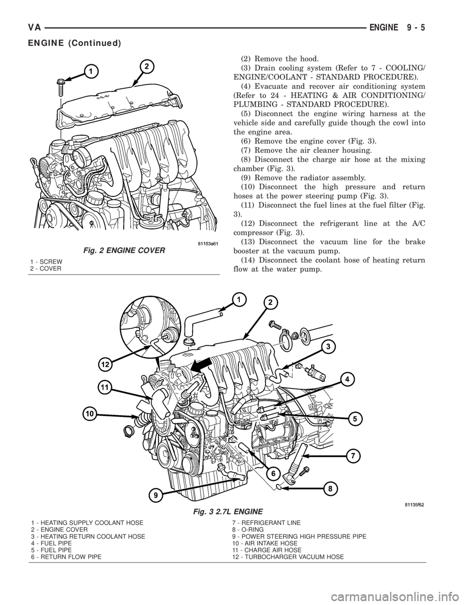
(1) Remove the retaining screws and remove cover
(Fig. 2).
REMOVAL
WARNING: RISK OF INJURY TO SKIN AND EYES
FROM SCALDING WITH HOT COOLANT. RISK OF
POISONING FROM SWALLOWING COOLANT. DO
NOT OPEN COOLING SYSTEM UNLESS COOLANT
TEMPERATURE IS BELOW 90ÉC (194ÉF). OPEN CAP
SLOWLY TO RELEASE PRESSURE. STORE COOL-
ANT IN SUITABLE AND APPROPRIATELY MARKED
CONTAINER. WEAR PROTECTIVE GLOVES,
CLOTHES, AND EYE WEAR.
CAUTION: STORE OR DISCARD ALL FLUIDS IN
SUITABLE AND APPROPRIATELY MARKED CON-
TAINERS.
(1) Disconnect the negative battery cable.
9 - 4 ENGINEVA
ENGINE (Continued)
Page 743 of 1232
(2) Remove the hood.
(3) Drain cooling system (Refer to 7 - COOLING/
ENGINE/COOLANT - STANDARD PROCEDURE).
(4) Evacuate and recover air conditioning system
(Refer to 24 - HEATING & AIR CONDITIONING/
PLUMBING - STANDARD PROCEDURE).
(5) Disconnect the engine wiring harness at the
vehicle side and carefully guide though the cowl into
the engine area.
(6) Remove the engine cover (Fig. 3).
(7) Remove the air cleaner housing.
(8) Disconnect the charge air hose at the mixing
chamber (Fig. 3).
(9) Remove the radiator assembly.
(10) Disconnect the high pressure and return
hoses at the power steering pump (Fig. 3).
(11) Disconnect the fuel lines at the fuel filter (Fig.
3).
(12) Disconnect the refrigerant line at the A/C
compressor (Fig. 3).
(13) Disconnect the vacuum line for the brake
booster at the vacuum pump.
(14) Disconnect the coolant hose of heating return
flow at the water pump.
Fig. 3 2.7L ENGINE
1 - HEATING SUPPLY COOLANT HOSE 7 - REFRIGERANT LINE
2 - ENGINE COVER 8 - O-RING
3 - HEATING RETURN COOLANT HOSE 9 - POWER STEERING HIGH PRESSURE PIPE
4 - FUEL PIPE 10 - AIR INTAKE HOSE
5 - FUEL PIPE 11 - CHARGE AIR HOSE
6 - RETURN FLOW PIPE 12 - TURBOCHARGER VACUUM HOSE
Fig. 2 ENGINE COVER
1 - SCREW
2 - COVER
VAENGINE 9 - 5
ENGINE (Continued)
Page 746 of 1232
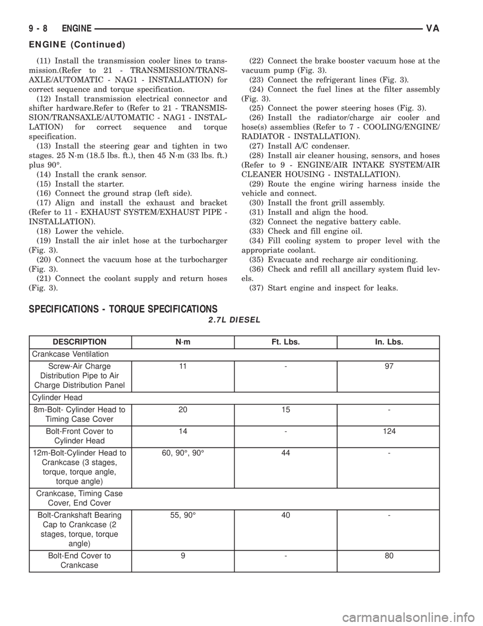
(11) Install the transmission cooler lines to trans-
mission.(Refer to 21 - TRANSMISSION/TRANS-
AXLE/AUTOMATIC - NAG1 - INSTALLATION) for
correct sequence and torque specification.
(12) Install transmission electrical connector and
shifter hardware.Refer to (Refer to 21 - TRANSMIS-
SION/TRANSAXLE/AUTOMATIC - NAG1 - INSTAL-
LATION) for correct sequence and torque
specification.
(13) Install the steering gear and tighten in two
stages. 25 N´m (18.5 lbs. ft.), then 45 N´m (33 lbs. ft.)
plus 90É.
(14) Install the crank sensor.
(15) Install the starter.
(16) Connect the ground strap (left side).
(17) Align and install the exhaust and bracket
(Refer to 11 - EXHAUST SYSTEM/EXHAUST PIPE -
INSTALLATION).
(18) Lower the vehicle.
(19) Install the air inlet hose at the turbocharger
(Fig. 3).
(20) Connect the vacuum hose at the turbocharger
(Fig. 3).
(21) Connect the coolant supply and return hoses
(Fig. 3).(22) Connect the brake booster vacuum hose at the
vacuum pump (Fig. 3).
(23) Connect the refrigerant lines (Fig. 3).
(24) Connect the fuel lines at the filter assembly
(Fig. 3).
(25) Connect the power steering hoses (Fig. 3).
(26) Install the radiator/charge air cooler and
hose(s) assemblies (Refer to 7 - COOLING/ENGINE/
RADIATOR - INSTALLATION).
(27) Install A/C condenser.
(28) Install air cleaner housing, sensors, and hoses
(Refer to 9 - ENGINE/AIR INTAKE SYSTEM/AIR
CLEANER HOUSING - INSTALLATION).
(29) Route the engine wiring harness inside the
vehicle and connect.
(30) Install the front grill assembly.
(31) Install and align the hood.
(32) Connect the negative battery cable.
(33) Check and fill engine oil.
(34) Fill cooling system to proper level with the
appropriate coolant.
(35) Evacuate and recharge air conditioning.
(36) Check and refill all ancillary system fluid lev-
els.
(37) Start engine and inspect for leaks.
SPECIFICATIONS - TORQUE SPECIFICATIONS
2.7L DIESEL
DESCRIPTION N´m Ft. Lbs. In. Lbs.
Crankcase Ventilation
Screw-Air Charge
Distribution Pipe to Air
Charge Distribution Panel11 - 9 7
Cylinder Head
8m-Bolt- Cylinder Head to
Timing Case Cover20 15 -
Bolt-Front Cover to
Cylinder Head14 - 124
12m-Bolt-Cylinder Head to
Crankcase (3 stages,
torque, torque angle,
torque angle)60, 90É, 90É 44 -
Crankcase, Timing Case
Cover, End Cover
Bolt-Crankshaft Bearing
Cap to Crankcase (2
stages, torque, torque
angle)55, 90É 40 -
Bolt-End Cover to
Crankcase9-80
9 - 8 ENGINEVA
ENGINE (Continued)
Page 748 of 1232
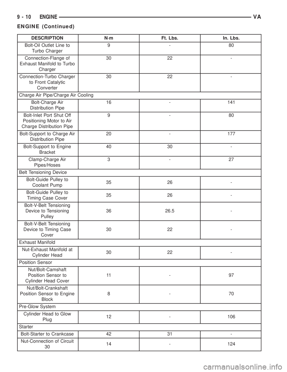
DESCRIPTION N´m Ft. Lbs. In. Lbs.
Bolt-Oil Outlet Line to
Turbo Charger9-80
Connection-Flange of
Exhaust Manifold to Turbo
Charger30 22 -
Connection-Turbo Charger
to Front Catalytic
Converter30 22 -
Charge Air Pipe/Charge Air Cooling
Bolt-Charge Air
Distribution Pipe16 - 141
Bolt-Inlet Port Shut Off
Positioning Motor to Air
Charge Distribution Pipe9-80
Bolt-Support to Charge Air
Distribution Pipe20 - 177
Bolt-Support to Engine
Bracket40 30 -
Clamp-Charge Air
Pipes/Hoses3-27
Belt Tensioning Device
Bolt-Guide Pulley to
Coolant Pump35 26 -
Bolt-Guide Pulley to
Timing Case Cover35 26 -
Bolt-V-Belt Tensioning
Device to Tensioning
Pulley36 26.5 -
Bolt-V-Belt Tensioning
Device to Timing Case
Cover30 22 -
Exhaust Manifold
Nut-Exhaust Manifold at
Cylinder Head30 22 -
Position Sensor
Nut/Bolt-Camshaft
Position Sensor to
Cylinder Head Cover11 - 9 7
Nut/Bolt-Crankshaft
Position Sensor to Engine
Block8-70
Pre-Glow System
Cylinder Head to Glow
Plug12 - 106
Starter
Bolt-Starter to Crankcase 42 31 -
Nut-Connection of Circuit
3014 - 124
9 - 10 ENGINEVA
ENGINE (Continued)
Page 749 of 1232
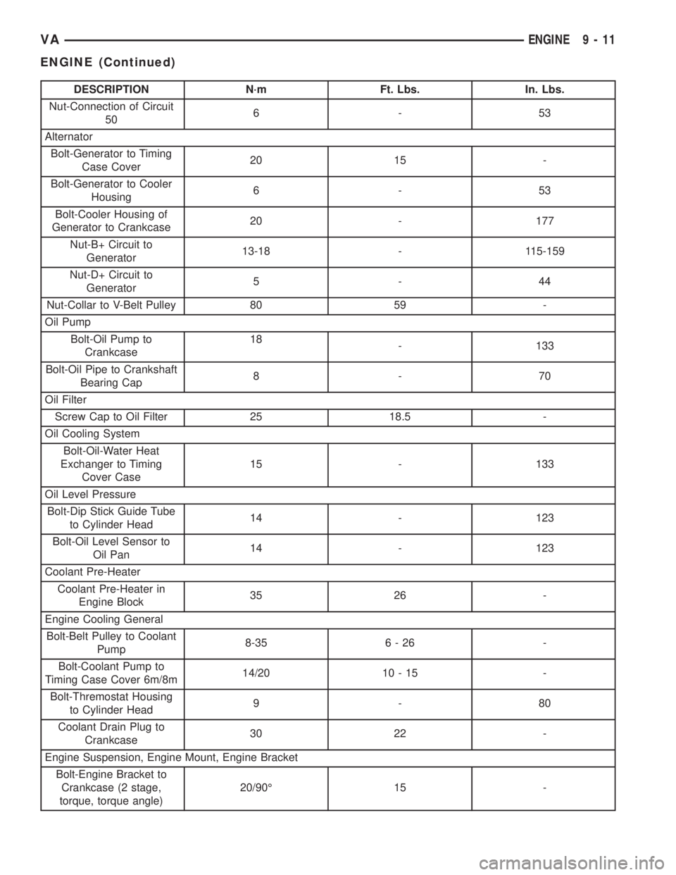
DESCRIPTION N´m Ft. Lbs. In. Lbs.
Nut-Connection of Circuit
506-53
Alternator
Bolt-Generator to Timing
Case Cover20 15 -
Bolt-Generator to Cooler
Housing6-53
Bolt-Cooler Housing of
Generator to Crankcase20 - 177
Nut-B+ Circuit to
Generator13-18 - 115-159
Nut-D+ Circuit to
Generator5-44
Nut-Collar to V-Belt Pulley 80 59 -
Oil Pump
Bolt-Oil Pump to
Crankcase18
- 133
Bolt-Oil Pipe to Crankshaft
Bearing Cap8-70
Oil Filter
Screw Cap to Oil Filter 25 18.5 -
Oil Cooling System
Bolt-Oil-Water Heat
Exchanger to Timing
Cover Case15 - 133
Oil Level Pressure
Bolt-Dip Stick Guide Tube
to Cylinder Head14 - 123
Bolt-Oil Level Sensor to
Oil Pan14 - 123
Coolant Pre-Heater
Coolant Pre-Heater in
Engine Block35 26 -
Engine Cooling General
Bolt-Belt Pulley to Coolant
Pump8-35 6 - 26 -
Bolt-Coolant Pump to
Timing Case Cover 6m/8m14/20 10 - 15 -
Bolt-Thremostat Housing
to Cylinder Head9-80
Coolant Drain Plug to
Crankcase30 22 -
Engine Suspension, Engine Mount, Engine Bracket
Bolt-Engine Bracket to
Crankcase (2 stage,
torque, torque angle)20/90É 15 -
VAENGINE 9 - 11
ENGINE (Continued)
Page 752 of 1232
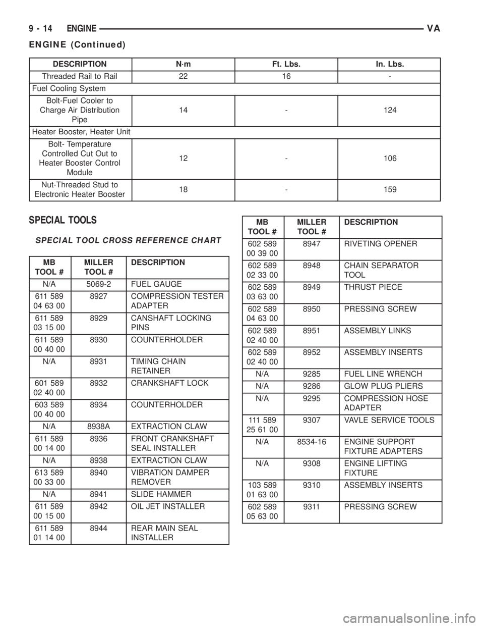
DESCRIPTION N´m Ft. Lbs. In. Lbs.
Threaded Rail to Rail 22 16 -
Fuel Cooling System
Bolt-Fuel Cooler to
Charge Air Distribution
Pipe14 - 124
Heater Booster, Heater Unit
Bolt- Temperature
Controlled Cut Out to
Heater Booster Control
Module12 - 106
Nut-Threaded Stud to
Electronic Heater Booster18 - 159
SPECIAL TOOLS
SPECIAL TOOL CROSS REFERENCE CHART
MB
TOOL #MILLER
TOOL #DESCRIPTION
N/A 5069-2 FUEL GAUGE
611 589
04 63 008927 COMPRESSION TESTER
ADAPTER
611 589
03 15 008929 CANSHAFT LOCKING
PINS
611 589
00 40 008930 COUNTERHOLDER
N/A 8931 TIMING CHAIN
RETAINER
601 589
02 40 008932 CRANKSHAFT LOCK
603 589
00 40 008934 COUNTERHOLDER
N/A 8938A EXTRACTION CLAW
611 589
00 14 008936 FRONT CRANKSHAFT
SEAL INSTALLER
N/A 8938 EXTRACTION CLAW
613 589
00 33 008940 VIBRATION DAMPER
REMOVER
N/A 8941 SLIDE HAMMER
611 589
00 15 008942 OIL JET INSTALLER
611 589
01 14 008944 REAR MAIN SEAL
INSTALLER
MB
TOOL #MILLER
TOOL #DESCRIPTION
602 589
00 39 008947 RIVETING OPENER
602 589
02 33 008948 CHAIN SEPARATOR
TOOL
602 589
03 63 008949 THRUST PIECE
602 589
04 63 008950 PRESSING SCREW
602 589
02 40 008951 ASSEMBLY LINKS
602 589
02 40 008952 ASSEMBLY INSERTS
N/A 9285 FUEL LINE WRENCH
N/A 9286 GLOW PLUG PLIERS
N/A 9295 COMPRESSION HOSE
ADAPTER
111 5 8 9
25 61 009307 VAVLE SERVICE TOOLS
N/A 8534-16 ENGINE SUPPORT
FIXTURE ADAPTERS
N/A 9308 ENGINE LIFTING
FIXTURE
103 589
01 63 009310 ASSEMBLY INSERTS
602 589
05 63 009311 PRESSING SCREW
9 - 14 ENGINEVA
ENGINE (Continued)