2005 MERCEDES-BENZ SPRINTER cooling
[x] Cancel search: coolingPage 760 of 1232
REMOVAL
REMOVAL - CYLINDER HEAD
(1) Disconnect negative battery cable.
(2) Position piston of cylinder #1 to ignition TDC.
(3) Raise and support vehicle.
(4) Install retaining lock # 8932 for crankshaft/
starter ring gear.
WARNING: RISK OF INJURY TO SKIN AND EYES
FROM SCALDING COOLANT. DO NOT OPEN COOL-
ING SYSTEM UNLESS TEMPERATURE IS BELOW
90ÉC (194ÉF). OPEN CAP SLOWLY TO RELEASE
PRESSURE. STORE COOLANT IN APPROVED CON-
TAINER ONLY. WEAR PROTECTIVE GLOVES,
CLOTHING AND EYE WEAR.
(5) Drain cooling system at radiator and crank-
case(Refer to 7 - COOLING/ENGINE/COOLANT -
STANDARD PROCEDURE).
(6) Lower vehicle.(7) Remove engine cover. (Refer to 9 - ENGINE
COVER- REMOVAL).
(8) Remove camshafts (Refer to 9 - ENGINE/CYL-
INDER HEAD/CAMSHAFT(S) - REMOVAL).
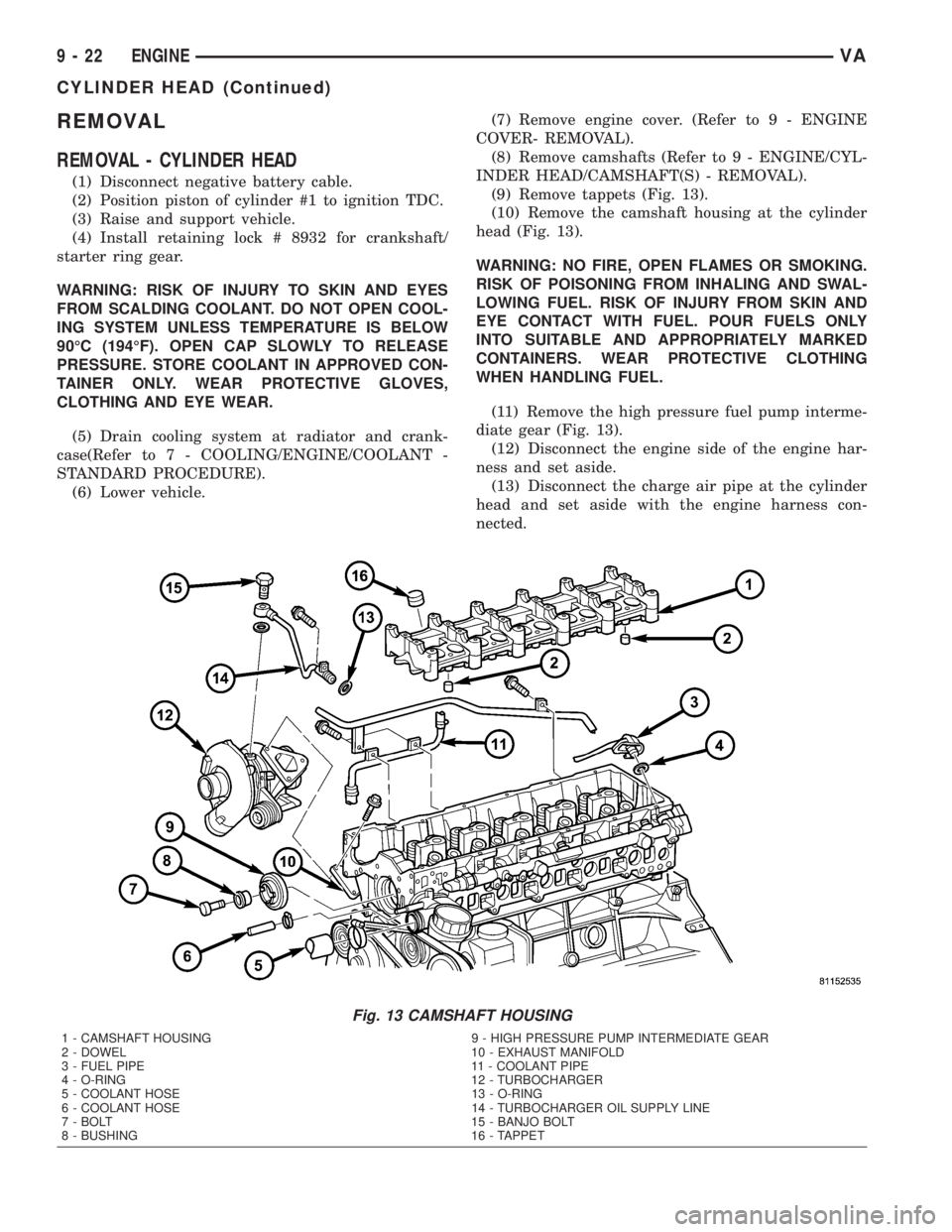
(9) Remove tappets (Fig. 13).
(10) Remove the camshaft housing at the cylinder
head (Fig. 13).
WARNING: NO FIRE, OPEN FLAMES OR SMOKING.
RISK OF POISONING FROM INHALING AND SWAL-
LOWING FUEL. RISK OF INJURY FROM SKIN AND
EYE CONTACT WITH FUEL. POUR FUELS ONLY
INTO SUITABLE AND APPROPRIATELY MARKED
CONTAINERS. WEAR PROTECTIVE CLOTHING
WHEN HANDLING FUEL.
(11) Remove the high pressure fuel pump interme-
diate gear (Fig. 13).
(12) Disconnect the engine side of the engine har-
ness and set aside.
(13) Disconnect the charge air pipe at the cylinder
head and set aside with the engine harness con-
nected.
Fig. 13 CAMSHAFT HOUSING
1 - CAMSHAFT HOUSING 9 - HIGH PRESSURE PUMP INTERMEDIATE GEAR
2 - DOWEL 10 - EXHAUST MANIFOLD
3 - FUEL PIPE 11 - COOLANT PIPE
4 - O-RING 12 - TURBOCHARGER
5 - COOLANT HOSE 13 - O-RING
6 - COOLANT HOSE 14 - TURBOCHARGER OIL SUPPLY LINE
7 - BOLT 15 - BANJO BOLT
8 - BUSHING 16 - TAPPET
9 - 22 ENGINEVA
CYLINDER HEAD (Continued)
Page 761 of 1232
(14) Disconnect the turbocharger oil supply line at
the cylinder head and turbocharger (Fig. 13).
(15) Disconnect the turbocharger at the exhaust
manifold (Fig. 13).
(16) Unbolt the transmission dipstick tube from
the cylinder head (Fig. 13).
(17) Disconnect the upper radiator hose and by
pass hose at the thermostat housing (Fig. 13).
NOTE: Capture any fuel spillage when disconnect-
ing fuel lines.
(18) Disconnect the fuel line at the rear of the fuel
rail (Fig. 13).
(19) Remove upper timing case to cylinder head
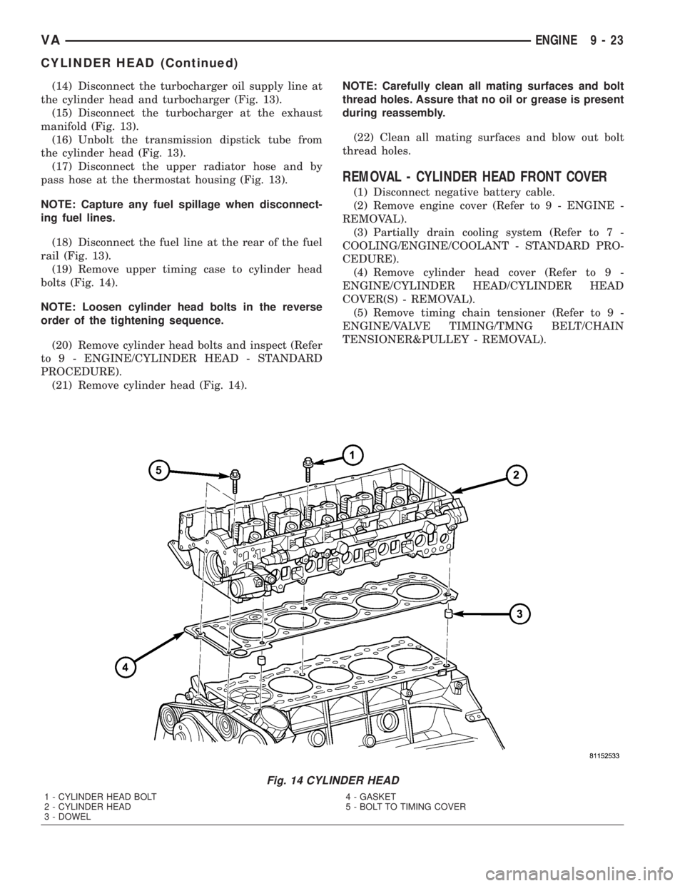
bolts (Fig. 14).
NOTE: Loosen cylinder head bolts in the reverse
order of the tightening sequence.
(20) Remove cylinder head bolts and inspect (Refer
to 9 - ENGINE/CYLINDER HEAD - STANDARD
PROCEDURE).
(21) Remove cylinder head (Fig. 14).NOTE: Carefully clean all mating surfaces and bolt
thread holes. Assure that no oil or grease is present
during reassembly.
(22) Clean all mating surfaces and blow out bolt
thread holes.
REMOVAL - CYLINDER HEAD FRONT COVER
(1) Disconnect negative battery cable.
(2) Remove engine cover (Refer to 9 - ENGINE -
REMOVAL).
(3) Partially drain cooling system (Refer to 7 -
COOLING/ENGINE/COOLANT - STANDARD PRO-
CEDURE).
(4) Remove cylinder head cover (Refer to 9 -
ENGINE/CYLINDER HEAD/CYLINDER HEAD
COVER(S) - REMOVAL).
(5) Remove timing chain tensioner (Refer to 9 -
ENGINE/VALVE TIMING/TMNG BELT/CHAIN
TENSIONER&PULLEY - REMOVAL).
Fig. 14 CYLINDER HEAD
1 - CYLINDER HEAD BOLT
2 - CYLINDER HEAD
3 - DOWEL4 - GASKET
5 - BOLT TO TIMING COVER
VAENGINE 9 - 23
CYLINDER HEAD (Continued)
Page 764 of 1232
BELT/CHAIN AND SPROCKETS - INSTALLATION)
Tighten to 80N´m (59 lbs.ft.).
(20) Remove retaining lock for crankshaft/starter
ring gear.
(21) Install air intake tube at turbocharger (Refer
to 11 - EXHAUST SYSTEM/TURBOCHARGER SYS-
TEM - INSTALLATION).
(22) Install engine cover (Refer to 9 - ENGINE -
INSTALLATION).
NOTE: DO NOT pressure test cooling system until
engine has reached operating temperature.
(23) Refill cooling system with proper coolant mix-
ture to proper level (Refer to 7 - COOLING/ENGINE/
COOLANT - STANDARD PROCEDURE).
(24) Connect negative battery cable.
WARNING: USE EXTREME CAUTION WHEN THE
ENGINE IS OPERATING. DO NOT STAND IN A
DIRECT LINE WITH THE FAN. DO NOT PUT YOUR
HANDS NEAR THE PULLEYS, BELTS OR FAN. DO
NOT WEAR LOOSE CLOTHES.
(25) Start engine and inspect for leaks. Care must
be taken to observe the fuel system warning (Refer to
14 - FUEL SYSTEM - WARNING)
INSTALLATION - CYLINDER HEAD FRONT
COVER
NOTE: Thoroughly clean all mating surfaces with
appropriate solvents to assure that no grease or oil
is present during reassembly.
NOTE: Dowel pins are used as a guide during
assembly and must remain in the proper position to
assure a good sealing surface.
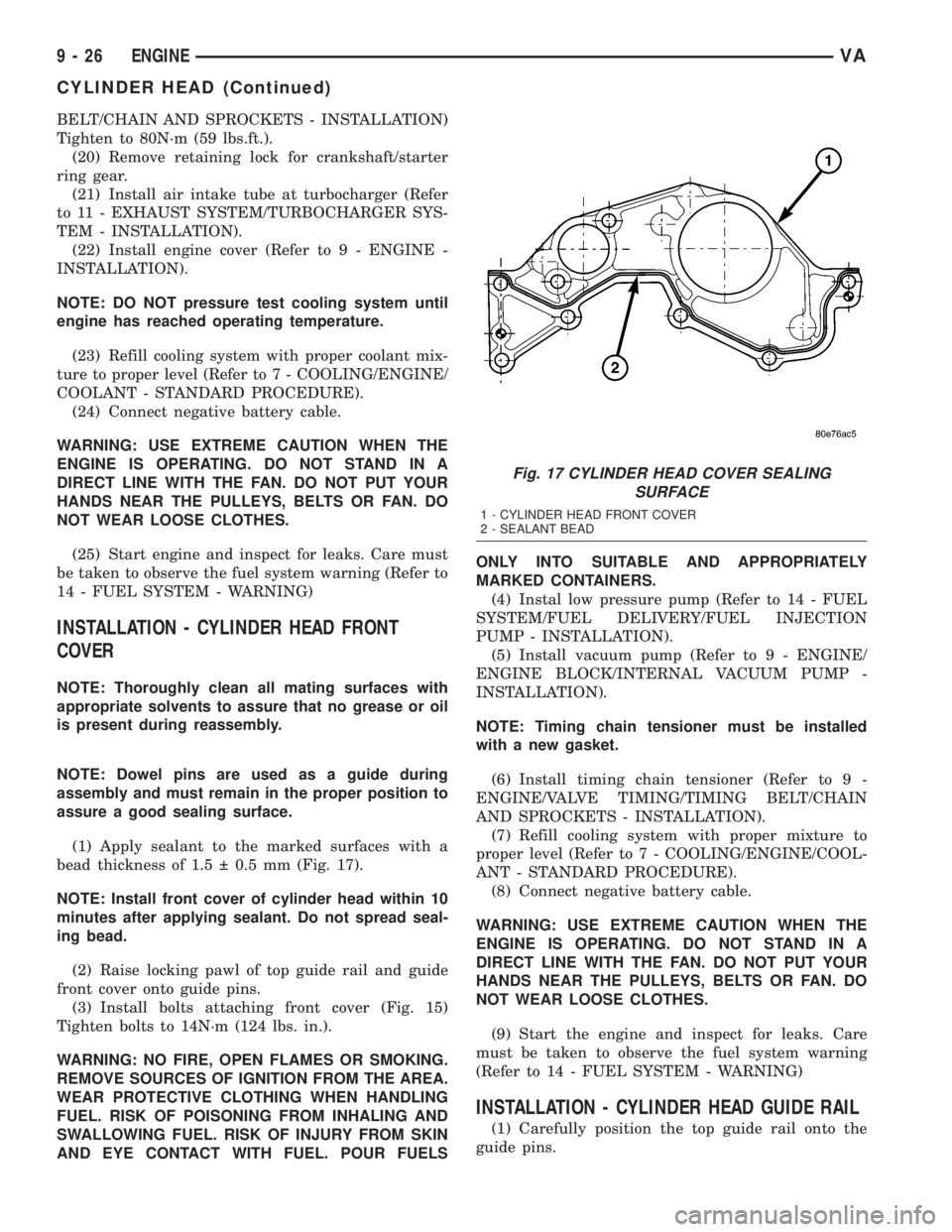
(1) Apply sealant to the marked surfaces with a
bead thickness of 1.5 0.5 mm (Fig. 17).
NOTE: Install front cover of cylinder head within 10
minutes after applying sealant. Do not spread seal-
ing bead.
(2) Raise locking pawl of top guide rail and guide
front cover onto guide pins.
(3) Install bolts attaching front cover (Fig. 15)
Tighten bolts to 14N´m (124 lbs. in.).
WARNING: NO FIRE, OPEN FLAMES OR SMOKING.
REMOVE SOURCES OF IGNITION FROM THE AREA.
WEAR PROTECTIVE CLOTHING WHEN HANDLING
FUEL. RISK OF POISONING FROM INHALING AND
SWALLOWING FUEL. RISK OF INJURY FROM SKIN
AND EYE CONTACT WITH FUEL. POUR FUELSONLY INTO SUITABLE AND APPROPRIATELY
MARKED CONTAINERS.
(4) Instal low pressure pump (Refer to 14 - FUEL
SYSTEM/FUEL DELIVERY/FUEL INJECTION
PUMP - INSTALLATION).
(5) Install vacuum pump (Refer to 9 - ENGINE/
ENGINE BLOCK/INTERNAL VACUUM PUMP -
INSTALLATION).
NOTE: Timing chain tensioner must be installed
with a new gasket.
(6) Install timing chain tensioner (Refer to 9 -
ENGINE/VALVE TIMING/TIMING BELT/CHAIN
AND SPROCKETS - INSTALLATION).
(7) Refill cooling system with proper mixture to
proper level (Refer to 7 - COOLING/ENGINE/COOL-
ANT - STANDARD PROCEDURE).
(8) Connect negative battery cable.
WARNING: USE EXTREME CAUTION WHEN THE
ENGINE IS OPERATING. DO NOT STAND IN A
DIRECT LINE WITH THE FAN. DO NOT PUT YOUR
HANDS NEAR THE PULLEYS, BELTS OR FAN. DO
NOT WEAR LOOSE CLOTHES.
(9) Start the engine and inspect for leaks. Care
must be taken to observe the fuel system warning
(Refer to 14 - FUEL SYSTEM - WARNING)
INSTALLATION - CYLINDER HEAD GUIDE RAIL
(1) Carefully position the top guide rail onto the
guide pins.
Fig. 17 CYLINDER HEAD COVER SEALING
SURFACE
1 - CYLINDER HEAD FRONT COVER
2 - SEALANT BEAD
9 - 26 ENGINEVA
CYLINDER HEAD (Continued)
Page 772 of 1232
ENGINE BLOCK
STANDARD PROCEDURE
STANDARD PROCEDURE - REPLACING ENGINE
CORE AND OIL GALLERY PLUGS
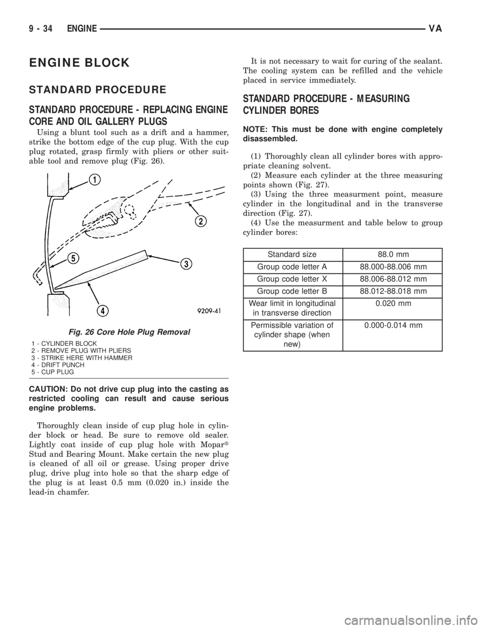
Using a blunt tool such as a drift and a hammer,
strike the bottom edge of the cup plug. With the cup
plug rotated, grasp firmly with pliers or other suit-
able tool and remove plug (Fig. 26).
CAUTION: Do not drive cup plug into the casting as
restricted cooling can result and cause serious
engine problems.
Thoroughly clean inside of cup plug hole in cylin-
der block or head. Be sure to remove old sealer.
Lightly coat inside of cup plug hole with Mopart
Stud and Bearing Mount. Make certain the new plug
is cleaned of all oil or grease. Using proper drive
plug, drive plug into hole so that the sharp edge of
the plug is at least 0.5 mm (0.020 in.) inside the
lead-in chamfer.It is not necessary to wait for curing of the sealant.
The cooling system can be refilled and the vehicle
placed in service immediately.
STANDARD PROCEDURE - MEASURING
CYLINDER BORES
NOTE: This must be done with engine completely
disassembled.
(1) Thoroughly clean all cylinder bores with appro-
priate cleaning solvent.
(2) Measure each cylinder at the three measuring
points shown (Fig. 27).
(3) Using the three measurment point, measure
cylinder in the longitudinal and in the transverse
direction (Fig. 27).
(4) Use the measurment and table below to group
cylinder bores:
Standard size 88.0 mm
Group code letter A 88.000-88.006 mm
Group code letter X 88.006-88.012 mm
Group code letter B 88.012-88.018 mm
Wear limit in longitudinal
in transverse direction0.020 mm
Permissible variation of
cylinder shape (when
new)0.000-0.014 mm
Fig. 26 Core Hole Plug Removal
1 - CYLINDER BLOCK
2 - REMOVE PLUG WITH PLIERS
3 - STRIKE HERE WITH HAMMER
4 - DRIFT PUNCH
5 - CUP PLUG
9 - 34 ENGINEVA
Page 774 of 1232
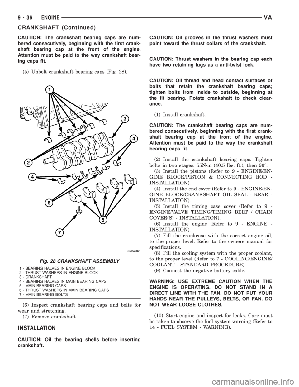
CAUTION: The crankshaft bearing caps are num-
bered consecutively, beginning with the first crank-
shaft bearing cap at the front of the engine.
Attention must be paid to the way crankshaft bear-
ing caps fit.
(5) Unbolt crankshaft bearing caps (Fig. 28).
(6) Inspect crankshaft bearing caps and bolts for
wear and stretching.
(7) Remove crankshaft.
INSTALLATION
CAUTION: Oil the bearing shells before inserting
crankshaft.CAUTION: Oil grooves in the thrust washers must
point toward the thrust collars of the crankshaft.
CAUTION: Thrust washers in the bearing cap each
have two retaining lugs as a anti-twist lock.
CAUTION: Oil thread and head contact surfaces of
bolts that retain the crankshaft bearing caps;
tighten bolts from inside to outside, beginning at
the fit bearing. Rotate crankshaft to check clear-
ance.
(1) Install crankshaft.
CAUTION: The crankshaft bearing caps are num-
bered consecutively, beginning with the first crank-
shaft bearing cap at the front of the engine.
Attention must be paid to the way the crankshaft
bearing caps fit.
(2) Install the crankshaft bearing caps. Tighten
bolts in two stages. 55N´m (40.5 lbs. ft.), then 90É.
(3) Install the pistons (Refer to 9 - ENGINE/EN-
GINE BLOCK/PISTON & CONNECTING ROD -
INSTALLATION).
(4) Install the end cover (Refer to 9 - ENGINE/EN-
GINE BLOCK/CRANKSHAFT OIL SEAL - REAR -
INSTALLATION).
(5) Install the timing case cover (Refer to 9 -
ENGINE/VALVE TIMING/TIMING BELT / CHAIN
COVER(S) - INSTALLATION).
(6) Install the engine (Refer to 9 - ENGINE -
INSTALLATION).
(7) Fill the crankcase with the correct engine oil,
to the proper level. Refer to the owners manual for
specifications.
(8) Fill the cooling system with the proper coolant,
to the proper level (Refer to 7 - COOLING/ENGINE/
COOLANT - STANDARD PROCEDURE).
(9) Connect the negative battery cable.
WARNING: USE EXTREME CAUTION WHEN THE
ENGINE IS OPERATING. DO NOT STAND IN A
DIRECT LINE WITH THE FAN. DO NOT PUT YOUR
HANDS NEAR THE PULLEYS, BELTS, OR FAN. DO
NOT WEAR LOOSE CLOTHES.
(10) Start engine and inspect for leaks. Care must
be taken to observe the fuel system warning (Refer to
14 - FUEL SYSTEM - WARNING).
Fig. 28 CRANKSHAFT ASSEMBLY
1 - BEARING HALVES IN ENGINE BLOCK
2 - THRUST WASHERS IN ENGINE BLOCK
3 - CRANKSHAFT
4 - BEARING HALVES IN MAIN BEARING CAPS
5 - MAIN BEARING CAPS
6 - THRUST WASHERS IN MAIN BEARING CAPS
7 - MAIN BEARING BOLTS
9 - 36 ENGINEVA
CRANKSHAFT (Continued)
Page 776 of 1232
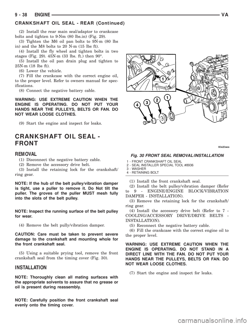
(2) Install the rear main seal/adaptor to crankcase
bolts and tighten to 9´Nm (80 lbs.in) (Fig. 29).
(3) Tighten the M6 oil pan bolts to 9N´m (80 lbs
in) and the M8 bolts to 20 N´m (15 lbs ft).
(4) Install the fly wheel and tighten bolts in two
stages (Fig. 29). 45N´m (33 lbs. ft.) then 90É.
(5) Install the oil pan drain plug and tighten to
25N´m (18 lbs ft).
(6) Lower the vehicle.
(7) Fill the crankcase with the correct engine oil,
to the proper level. Refer to owners manual for spec-
ifications.
(8) Connect the negative battery cable.
WARNING: USE EXTREME CAUTION WHEN THE
ENGINE IS OPERATING. DO NOT PUT YOUR
HANDS NEAR THE PULLEYS, BELTS OR FAN. DO
NOT WEAR LOOSE CLOTHES.
(9) Start the engine and inspect for leaks.
CRANKSHAFT OIL SEAL -
FRONT
REMOVAL
(1) Disconnect the negative battery cable.
(2) Remove the accessory drive belt.
(3) Install the retaining lock for the crankshaft/
ring gear.
NOTE: If the hub of the belt pulley/vibration damper
is tight, use a puller to remove it. Do Not tilt the
puller. The groves of the puller MUST mesh fully
into the slots of the belt pulley.
NOTE: Inspect the running surface of the belt pulley
for wear.
(4) Remove the belt pully/vibration damper.
CAUTION: Care must be taken to prevent severe
damage to the crankshaft and mounting whole for
the front crankshaft seal.
(5) Using a suitable prying tool, remove the front
crankshaft seal from the timing cover (Fig. 30).
INSTALLATION
NOTE: Thoroughly clean all mating surfaces with
the appropriate solvents to assure that no grease or
oil is present during reassembly.
NOTE: Carefully position the front crankshaft seal
evenly onto the timing cover.(1) Install the front crankshaft seal.
(2) Install the belt pulley/vibration damper (Refer
to 9 - ENGINE/ENGINE BLOCK/VIBRATION
DAMPER - INSTALLATION).
(3) Remove the retaining lock for the crankshaft/
ring gear.
(4) Install the accessory drive belt (Refer to 7 -
COOLING/ACCESSORY DRIVE/DRIVE BELTS -
INSTALLATION).
(5) Reconnect the negative battery cable.
(6) Fill the crankcase with the correct engine oil to
the proper level.
WARNING: USE EXTREME CAUTION WHEN THE
ENGINE IS OPERATING. DO NOT STAND IN A
DIRECT LINE WITH THE FAN. DO NOT PUT YOUR
HANDS NEAR THE PULLEYS, BELTS OR FAN. DO
NOT WEAR LOOSE CLOTHES.
(7) Start the engine and inspect for leaks.
Fig. 30 FRONT SEAL REMOVAL/INSTALLATION
1 - FRONT CRANKSHAFT OIL SEAL
2 - SEAL INSTALLER SPECIAL TOOL #8936
3 - WASHER
4 - RETAINING BOLT
9 - 38 ENGINEVA
CRANKSHAFT OIL SEAL - REAR (Continued)
Page 782 of 1232
CAUTION: Assemble the piston and connecting rod
so that the arrow is pointing in the direction of
travel (in the opposite direction of power flow). The
marking on the connecting rod is pointing toward
the inlet side.
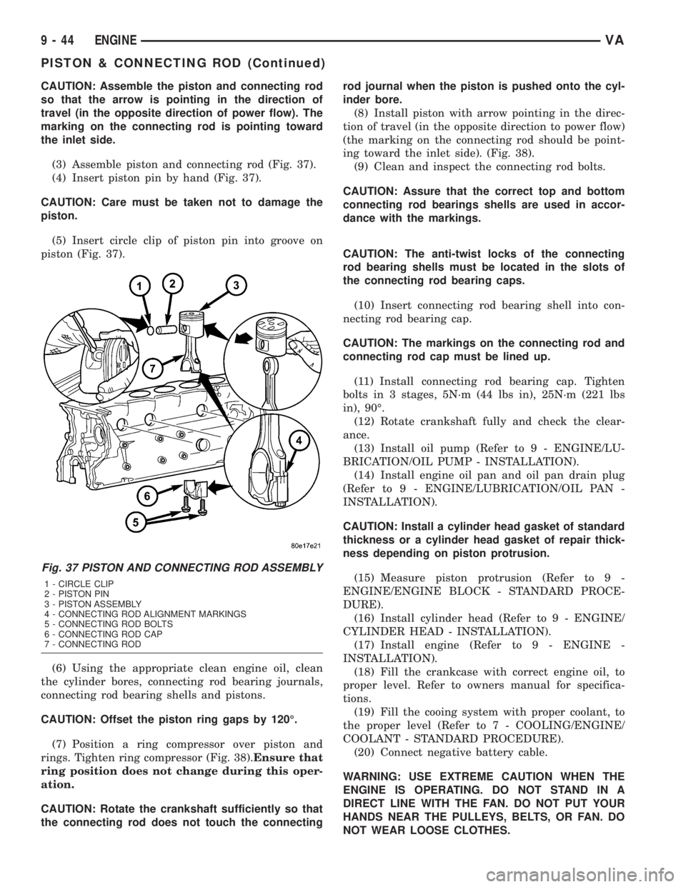
(3) Assemble piston and connecting rod (Fig. 37).
(4) Insert piston pin by hand (Fig. 37).
CAUTION: Care must be taken not to damage the
piston.
(5) Insert circle clip of piston pin into groove on
piston (Fig. 37).
(6) Using the appropriate clean engine oil, clean
the cylinder bores, connecting rod bearing journals,
connecting rod bearing shells and pistons.
CAUTION: Offset the piston ring gaps by 120É.
(7) Position a ring compressor over piston and
rings. Tighten ring compressor (Fig. 38).Ensure that
ring position does not change during this oper-
ation.
CAUTION: Rotate the crankshaft sufficiently so that
the connecting rod does not touch the connectingrod journal when the piston is pushed onto the cyl-
inder bore.
(8) Install piston with arrow pointing in the direc-
tion of travel (in the opposite direction to power flow)
(the marking on the connecting rod should be point-
ing toward the inlet side). (Fig. 38).
(9) Clean and inspect the connecting rod bolts.
CAUTION: Assure that the correct top and bottom
connecting rod bearings shells are used in accor-
dance with the markings.
CAUTION: The anti-twist locks of the connecting
rod bearing shells must be located in the slots of
the connecting rod bearing caps.
(10) Insert connecting rod bearing shell into con-
necting rod bearing cap.
CAUTION: The markings on the connecting rod and
connecting rod cap must be lined up.
(11) Install connecting rod bearing cap. Tighten
bolts in 3 stages, 5N´m (44 lbs in), 25N´m (221 lbs
in), 90É.
(12) Rotate crankshaft fully and check the clear-
ance.
(13) Install oil pump (Refer to 9 - ENGINE/LU-
BRICATION/OIL PUMP - INSTALLATION).
(14) Install engine oil pan and oil pan drain plug
(Refer to 9 - ENGINE/LUBRICATION/OIL PAN -
INSTALLATION).
CAUTION: Install a cylinder head gasket of standard
thickness or a cylinder head gasket of repair thick-
ness depending on piston protrusion.
(15) Measure piston protrusion (Refer to 9 -
ENGINE/ENGINE BLOCK - STANDARD PROCE-
DURE).
(16) Install cylinder head (Refer to 9 - ENGINE/
CYLINDER HEAD - INSTALLATION).
(17) Install engine (Refer to 9 - ENGINE -
INSTALLATION).
(18) Fill the crankcase with correct engine oil, to
proper level. Refer to owners manual for specifica-
tions.
(19) Fill the cooing system with proper coolant, to
the proper level (Refer to 7 - COOLING/ENGINE/
COOLANT - STANDARD PROCEDURE).
(20) Connect negative battery cable.
WARNING: USE EXTREME CAUTION WHEN THE
ENGINE IS OPERATING. DO NOT STAND IN A
DIRECT LINE WITH THE FAN. DO NOT PUT YOUR
HANDS NEAR THE PULLEYS, BELTS, OR FAN. DO
NOT WEAR LOOSE CLOTHES.
Fig. 37 PISTON AND CONNECTING ROD ASSEMBLY
1 - CIRCLE CLIP
2 - PISTON PIN
3 - PISTON ASSEMBLY
4 - CONNECTING ROD ALIGNMENT MARKINGS
5 - CONNECTING ROD BOLTS
6 - CONNECTING ROD CAP
7 - CONNECTING ROD
9 - 44 ENGINEVA
PISTON & CONNECTING ROD (Continued)
Page 785 of 1232
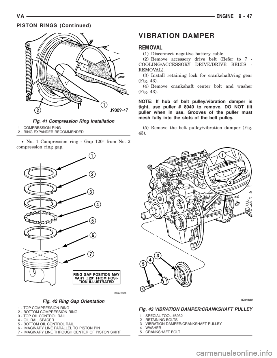
²No. 1 Compression ring - Gap 120É from No. 2
compression ring gap.
VIBRATION DAMPER
REMOVAL
(1) Disconnect negative battery cable.
(2) Remove accessory drive belt (Refer to 7 -
COOLING/ACCESSORY DRIVE/DRIVE BELTS -
REMOVAL).
(3) Install retaining lock for crankshaft/ring gear
(Fig. 43).
(4) Remove crankshaft center bolt and washer
(Fig. 43).
NOTE: If hub of belt pulley/vibration damper is
tight, use puller # 8940 to remove. DO NOT tilt
puller when in use. Grooves of the puller must
mesh fully into the slots of the belt pulley.
(5) Remove the belt pulley/vibration damper (Fig.
43).
Fig. 41 Compression Ring Installation
1 - COMPRESSION RING
2 - RING EXPANDER RECOMMENDED
Fig. 42 Ring Gap Orientation
1 - TOP COMPRESSION RING
2 - BOTTOM COMPRESSION RING
3 - TOP OIL CONTROL RAIL
4 - OIL RAIL SPACER
5 - BOTTOM OIL CONTROL RAIL
6 - IMAGINARY LINE PARALLEL TO PISTON PIN
7 - IMAGINARY LINE THROUGH CENTER OF PISTON SKIRTFig. 43 VIBRATION DAMPER/CRANKSHAFT PULLEY
1 - SPECIAL TOOL #8932
2 - RETAINING BOLTS
3 - VIBRATION DAMPER/CRANKSHAFT PULLEY
4 - WASHER
5 - CRANKSHAFT BOLT
VAENGINE 9 - 47
PISTON RINGS (Continued)