2005 MERCEDES-BENZ SPRINTER cooling
[x] Cancel search: coolingPage 1130 of 1232
²expansion valve
²air outlet temperature sensor
²mode doors
Vehicles equipped with the factory-installed
optional rear air conditioning system (Fig. 2) use a
common roof mounted assembly which includes:
²solenoid valve
²evaporator core
²evaporator temperature sensor
²expansion valve
²blower motor and wheel assembly
A heater booster is used to aid in warming the
engine coolant. The heater booster system can be
switched on while the vehicle is being driven to help
the engine reach its normal operating temperature
quickly and will help aid in heating up the air within
the passenger compartment quickly when requested
by the operator (Fig. 3).
OPERATION - HEATER AND AIR CONDITIONER
Outside air enters the vehicle through the hood
opening at the base of the windshield, and passesthrough the ventilation housing located in the engine
compartment into the heater housing located behind
the instrument panel. Air flow velocity is adjusted
with the blower motor speed selector thumbwheel on
the A/C-heater control. The air intake openings must
be kept free of snow, ice, leaves, and other obstruc-
tions for the HVAC system to receive a sufficient vol-
ume of outside air.
The automatic temperature control (ATC) system
controls interior temperature by taking actual values
from the temperature sensors and the CAN bus and
comparing them to the nominal value of the temper-
ature control switch. The electric pulsed heater valve
is then energized depending on the requested quan-
tity of heat and an electrically-operated water pump
gives a nearly constant water flow for exact temper-
ature regulation. If the solenoid is not energized, the
coolant circuit to the heat exchanger is fully open. To
control the temperature the solenoid valve is pulsed
by the ATC in periods of four seconds.
The mode control knob on the A/C-heater control is
used to direct the conditioned air flow to the selected
air outlets. The mode control knob operates the mode
doors by cables connected to the mode doors.
When the outside air contains smoke, oders, high
humidity, or if rapid cooling is desired, interior air
can by recirculated by selecting the Recirculation
Mode with the mode control knob. The mode control
knob operates the recirculation door through use of a
vaccum actuator. When the Recirculation Mode is
selected, the recirculation door is closed to prevent
outside air from entering the passenger compart-
ment.
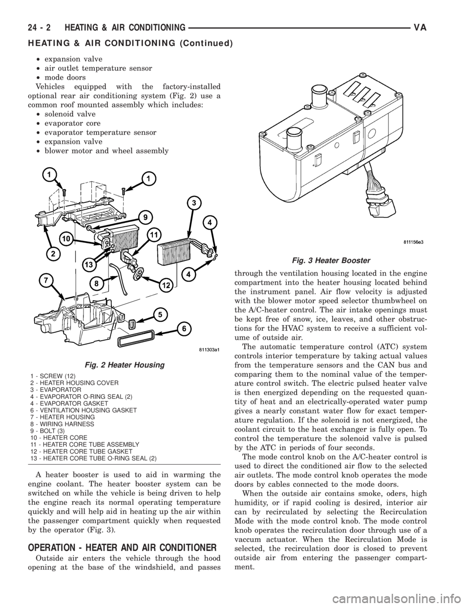
Fig. 2 Heater Housing
1 - SCREW (12)
2 - HEATER HOUSING COVER
3 - EVAPORATOR
4 - EVAPORATOR O-RING SEAL (2)
4 - EVAPORATOR GASKET
6 - VENTILATION HOUSING GASKET
7 - HEATER HOUSING
8 - WIRING HARNESS
9 - BOLT (3)
10 - HEATER CORE
11 - HEATER CORE TUBE ASSEMBLY
12 - HEATER CORE TUBE GASKET
13 - HEATER CORE TUBE O-RING SEAL (2)
Fig. 3 Heater Booster
24 - 2 HEATING & AIR CONDITIONINGVA
HEATING & AIR CONDITIONING (Continued)
Page 1132 of 1232
c. With the engine running, duct temperature
should not be less than 2É C (35É F) or than 12É C
(54É F).
(7) If the compressor has not cycled off and the
duct temperature is less than 2É C (35É F) , check the
evaporator temperature sensor and circuit by per-
forming the ATC Function Test (Refer to 24 - HEAT-
ING & AIR CONDITIONING - DIAGNOSIS AND
TESTING).
(8) If duct output temperature is not within speci-
fications, check the refrigerant system for leaks and
proper refrigerant charge (Refer to 24 - HEATING &
AIR CONDITIONING/PLUMBING - DIAGNOSIS
AND TESTING) and (Refer to 24 - HEATING & AIR
CONDITIONING/PLUMBING - STANDARD PRO-
CEDURE).
DIAGNOSIS AND TESTING - HEATER
PERFORMANCE
Before performing the following tests, perform the
ATC Function Test using the DRBIIItand refer toCooling for the procedures to check the radiator cool-
ant level, serpentine drive belt tension, radiator air
flow and the radiator fan operation.
MAXIMUM HEATER OUTPUT
Engine coolant is provided to the heater core
through a heater valve and heater hose. With the
engine idling at normal operating temperature, set
the heater-A/C controls as follows:
²Temperature control in the full hot position
²Mode control in the floor heat position
²Blower motor control in the highest speed posi-
tion
Using a test thermometer, check the temperature
of the air being discharged at the floor outlets. Com-
pare the test thermometer reading to the Tempera-
ture Reference chart.
TEMPERATURE REFERENCE CHART
Ambient Temperature Minimum Floor Outlet Temperature
Celsius Fahreheit Celsius Fahreheit
15.5É 60É 62.2É 144É
21.1É 70É 63.8É 147É
26.6É 80É 65.5É 150É
32.2É 90É 67.2É 153É
If the floor outlet air temperature is insufficient,
check for a faulty heater valve (perform ATC Func-
tion Test) and verify that the cooling system is oper-
ating to specifications (Refer to 7 - COOLING/
ENGINE/COOLANT - DIAGNOSIS AND TESTING).
Both of the heater hoses should be HOT to the touch
(the coolant return heater hose should be slightly
cooler than the supply hose. If the coolant return
hose is much cooler than the supply hose, locate and
repair the engine coolant flow obstruction in the
heater system.
POSSIBLE LOCATIONS OR CAUSE OF
OBSTRUCTED COOLANT FLOW
²Pinched or kinked heater hoses.
²Improper heater hose routing.
²Plugged heater hoses or supply and return ports
at the cooling system connections.
²Inoperative or stuck heater water valve.
²Plugged heater core.If proper coolant flow is verified, and heater floor
outlet air temperature is insufficient, a mechanical
problem may exist.
POSSIBLE LOCATIONS OR CAUSE OF
INSUFFICIENT HEAT
²An obstructed cowl air intake.
²Obstructed heater system outlets.
²Heater water valve not functioning properly.
TEMPERATURE CONTROL
If outlet air temperature cannot be adjusted with
the A/C-heater temperature control, one of the follow-
ing could require service:
²Faulty A/C-heater control switch.
²Faulty temperature sensor.
²Faulty A/C-heater control cable or actuator.
²Faulty A/C-heater control module.
24 - 4 HEATING & AIR CONDITIONINGVA
HEATING & AIR CONDITIONING (Continued)
Page 1137 of 1232
The compressor clutch engagement is controlled by
several components:
²A/C switch on the A/C-heater control panel
²Evaporator temperature sensor
²A/C pressure transducer
²Air temperature sensor
²CAN bus messages
The compressor clutch is de-energized under any of
the following conditions:
²Blocked compressor (thermal fuse in the pulley)
²Low pressure in the system
²Low evaporator temperature
²Hard acceleration (WOT)
²High coolant temperatures
STANDARD PROCEDURE
STANDARD PROCEDURE - COMPRESSOR
CLUTCH AIR GAP
If a new clutch plate and/or clutch pulley are being
used, the air gap between the clutch plate and clutch
pulley must be checked using the following proce-
dure:
(1) Using feeler gauges, measure the air gap
between the clutch plate and the clutch pulley fric-
tion surfaces.
(2) If the air gap is not between 0.5 and 0.9 mm
(0.020 and 0.035 in.), add or subtract shims until the
desired air gap is obtained.
NOTE: The shims may compress after tightening
the compressor shaft bolt. Check the air gap in four
or more places on the clutch plate to verify that theair gap is still correct. Spin the clutch pulley before
making the final air gap check.
STANDARD PROCEDURE - COMPRESSOR
CLUTCH BREAK-IN
After a new compressor clutch has been installed,
cycle the compressor clutch approximately twenty
times (five seconds on, then five seconds off). During
this procedure, set the heater-A/C control in the
Recirculation Mode, the A/C button in the on posi-
tion, the blower motor switch in the highest speed
position, and the engine speed at 1500 to 2000 rpm.
This procedure (burnishing) will seat the opposing
friction surfaces and provide a higher compressor
clutch torque capability.
REMOVAL
The refrigerant system can remain fully-charged
during compressor clutch, pulley, or coil replacement.
The compressor clutch can be serviced in the vehicle.
(1) Disconnect and isolate the battery negative
cable.
(2) Remove the serpentine drive belt (Refer to 7 -
COOLING/ACCESSORY DRIVE/DRIVE BELTS -
REMOVAL).
(3) Disconnect the engine wire harness connector
for the compressor clutch coil from the clutch coil
wire harness connector on the top of the compressor.
(4) Disengage the retainer on the engine wire har-
ness compressor clutch coil lead from the bracket on
the top of the compressor.
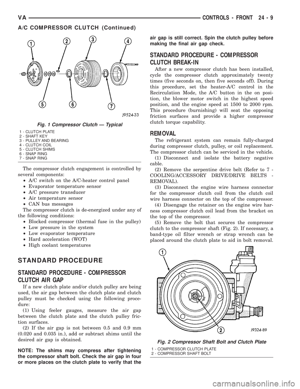
(5) Remove the bolt that secures the compressor
clutch to the compressor shaft (Fig. 2). If necessary, a
band-type oil filter wrench or strap wrench can be
placed around the clutch plate to aid in bolt removal.
Fig. 1 Compressor Clutch Ð Typical
1 - CLUTCH PLATE
2 - SHAFT KEY
3 - PULLEY AND BEARING
4 - CLUTCH COIL
5 - CLUTCH SHIMS
6 - SNAP RING
7 - SNAP RING
Fig. 2 Compressor Shaft Bolt and Clutch Plate
1 - COMPRESSOR CLUTCH PLATE
2 - COMPRESSOR SHAFT BOLT
VACONTROLS - FRONT 24 - 9
A/C COMPRESSOR CLUTCH (Continued)
Page 1140 of 1232
(11) Reconnect the engine wire harness connector
for the compressor clutch coil to the coil wire harness
connector on the top of the compressor.
(12) Reinstall the serpentine accessory drive belt
(Refer to 7 - COOLING/ACCESSORY DRIVE/DRIVE
BELTS - INSTALLATION).
(13) Reconnect the battery negative cable.
(14) If a new clutch plate and/or clutch pulley are
being installed, the new clutch components must be
burnished (Refer to 24 - HEATING & AIR CONDI-
TIONING/CONTROLS/A/C COMPRESSOR CLUTCH
- STANDARD PROCEDURE).
A/C COMPRESSOR CLUTCH
COIL
DIAGNOSIS AND TESTING - COMPRESSOR
CLUTCH COIL
The air conditioning compressor clutch coil electri-
cal circuit is controlled by the ATC control module
which is integral to the heater-A/C control. Begin
testing of a suspected compressor clutch coil problem
by performing the ATC Function Test using the
DRBIIItscan tool.
A/C HEATER CONTROL
DESCRIPTION
This ATC system uses a combination of electrical
and mechanical controls. These controls provide the
vehicle operator with a number of setting options to
help control the climate and comfort within the vehi-
cle.
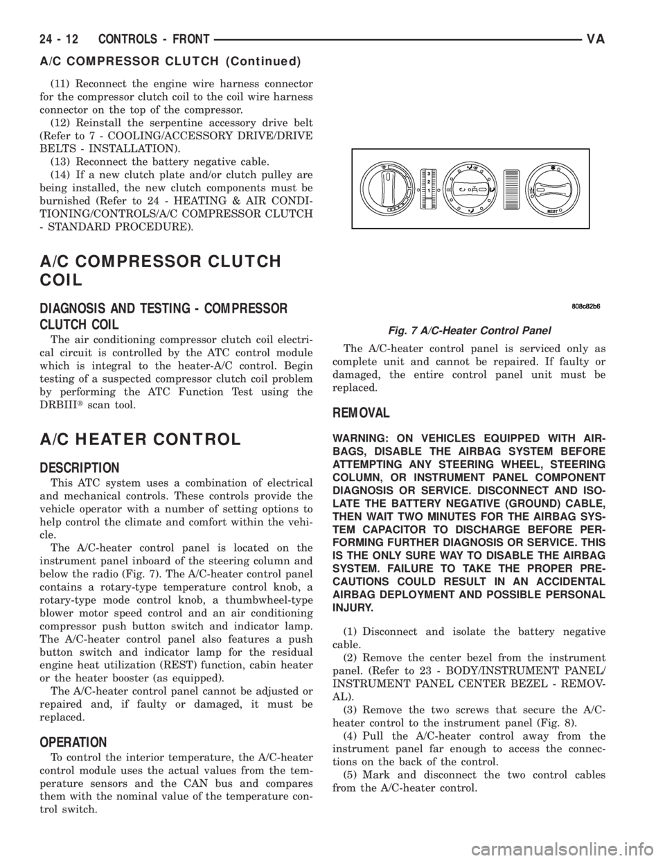
The A/C-heater control panel is located on the
instrument panel inboard of the steering column and
below the radio (Fig. 7). The A/C-heater control panel
contains a rotary-type temperature control knob, a
rotary-type mode control knob, a thumbwheel-type
blower motor speed control and an air conditioning
compressor push button switch and indicator lamp.
The A/C-heater control panel also features a push
button switch and indicator lamp for the residual
engine heat utilization (REST) function, cabin heater
or the heater booster (as equipped).
The A/C-heater control panel cannot be adjusted or
repaired and, if faulty or damaged, it must be
replaced.
OPERATION
To control the interior temperature, the A/C-heater
control module uses the actual values from the tem-
perature sensors and the CAN bus and compares
them with the nominal value of the temperature con-
trol switch.The A/C-heater control panel is serviced only as
complete unit and cannot be repaired. If faulty or
damaged, the entire control panel unit must be
replaced.
REMOVAL
WARNING: ON VEHICLES EQUIPPED WITH AIR-
BAGS, DISABLE THE AIRBAG SYSTEM BEFORE
ATTEMPTING ANY STEERING WHEEL, STEERING
COLUMN, OR INSTRUMENT PANEL COMPONENT
DIAGNOSIS OR SERVICE. DISCONNECT AND ISO-
LATE THE BATTERY NEGATIVE (GROUND) CABLE,
THEN WAIT TWO MINUTES FOR THE AIRBAG SYS-
TEM CAPACITOR TO DISCHARGE BEFORE PER-
FORMING FURTHER DIAGNOSIS OR SERVICE. THIS
IS THE ONLY SURE WAY TO DISABLE THE AIRBAG
SYSTEM. FAILURE TO TAKE THE PROPER PRE-
CAUTIONS COULD RESULT IN AN ACCIDENTAL
AIRBAG DEPLOYMENT AND POSSIBLE PERSONAL
INJURY.
(1) Disconnect and isolate the battery negative
cable.
(2) Remove the center bezel from the instrument
panel. (Refer to 23 - BODY/INSTRUMENT PANEL/
INSTRUMENT PANEL CENTER BEZEL - REMOV-
AL).
(3) Remove the two screws that secure the A/C-
heater control to the instrument panel (Fig. 8).
(4) Pull the A/C-heater control away from the
instrument panel far enough to access the connec-
tions on the back of the control.
(5) Mark and disconnect the two control cables
from the A/C-heater control.
Fig. 7 A/C-Heater Control Panel
24 - 12 CONTROLS - FRONTVA
A/C COMPRESSOR CLUTCH (Continued)
Page 1141 of 1232
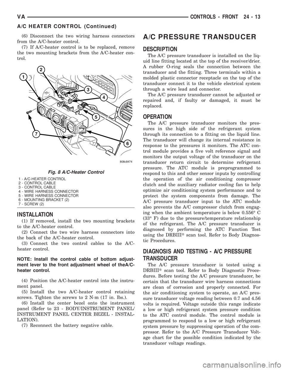
(6) Disconnect the two wiring harness connectors
from the A/C-heater control.
(7) If A/C-heater control is to be replaced, remove
the two mounting brackets from the A/C-heater con-
trol.
INSTALLATION
(1) If removed, install the two mounting brackets
to the A/C-heater control.
(2) Connect the two wire harness connectors into
the back of the A/C-heater control.
(3) Connect the two control cables to the A/C-
heater control.
NOTE: Install the control cable of bottom adjust-
ment lever to the front adjustment wheel of theA/C-
heater control.
(4) Position the A/C-heater control into the instru-
ment panel.
(5) Install the two A/C-heater control retaining
screws. Tighten the screws to 2 N´m (17 in. lbs.).
(6) Install the center bezel onto the instrument
panel (Refer to 23 - BODY/INSTRUMENT PANEL/
INSTRUMENT PANEL CENTER BEZEL - INSTAL-
LATION).
(7) Reconnect the battery negative cable.
A/C PRESSURE TRANSDUCER
DESCRIPTION
The A/C pressure transducer is installed on the liq-
uid line fitting located at the top of the receiver/drier.
A rubber O-ring seals the connection between the
transducer and the fitting. Three terminals within a
molded plastic connector receptacle on the top of the
transducer connect it to the vehicle electrical system
through a wire lead and connector.
The A/C pressure transducer cannot be adjusted or
repaired and, if faulty or damaged, it must be
replaced.
OPERATION
The A/C pressure transducer monitors the pres-
sures in the high side of the refrigerant system
through its connection to a fitting on the liquid line.
The transducer will change its internal resistance in
response to the pressures it monitors. The ATC con-
trol module provides a five volt reference signal and
monitors the output voltage of the transducer on the
transducer return circuit to determine refrigerant
pressure. The ATC module is preprogrammed to
respond to this and other sensor inputs by controlling
the operation of the air conditioning compressor
clutch and the auxiliary radiator cooling fan to help
optimize air conditioning system performance and to
protect the system components from damage. The
A/C pressure transducer input to the ATC module
also prevents the A/C compressor clutch from engag-
ing when the ambient temperature is below 0.556É C
(33É F) due to the pressure/temperature relationship
of the refrigerant. The A/C pressure transducer is
diagnosed by performing the ATC Function Test
using the DRBIIItscan tool. Refer to Body Diagnos-
tic Procedures.
DIAGNOSIS AND TESTING - A/C PRESSURE
TRANSDUCER
The A/C pressure transducer is tested using a
DRBIIItscan tool. Refer to Body Diagnostic Proce-
dures. Before testing the A/C pressure transducer, be
certain that the transducer wire harness connections
are clean of corrosion and properly connected. For
the air conditioning system to operate, an A/C pres-
sure transducer voltage reading between 0.7 and 4.56
volts is required. Voltage outside this range indicate
a low or high refrigerant system pressure condition
to the ATC control module. The control module is
programmed to respond to a low or high refrigerant
system pressure by suppressing operation of the com-
pressor. Refer to the A/C Pressure Transducer Volt-
age chart for the possible condition indicated by the
transducer voltage readings.
Fig. 8 A/C-Heater Control
1 - A/C-HEATER CONTROL
2 - CONTROL CABLE
3 - CONTROL CABLE
4 - WIRE HARNESS CONNECTOR
5 - WIRE HARNESS CONNECTOR
6 - MOUNTING BRACKET (2)
7 - SCREW (2)
VACONTROLS - FRONT 24 - 13
A/C HEATER CONTROL (Continued)
Page 1157 of 1232
TEMPERATURE CONTROL
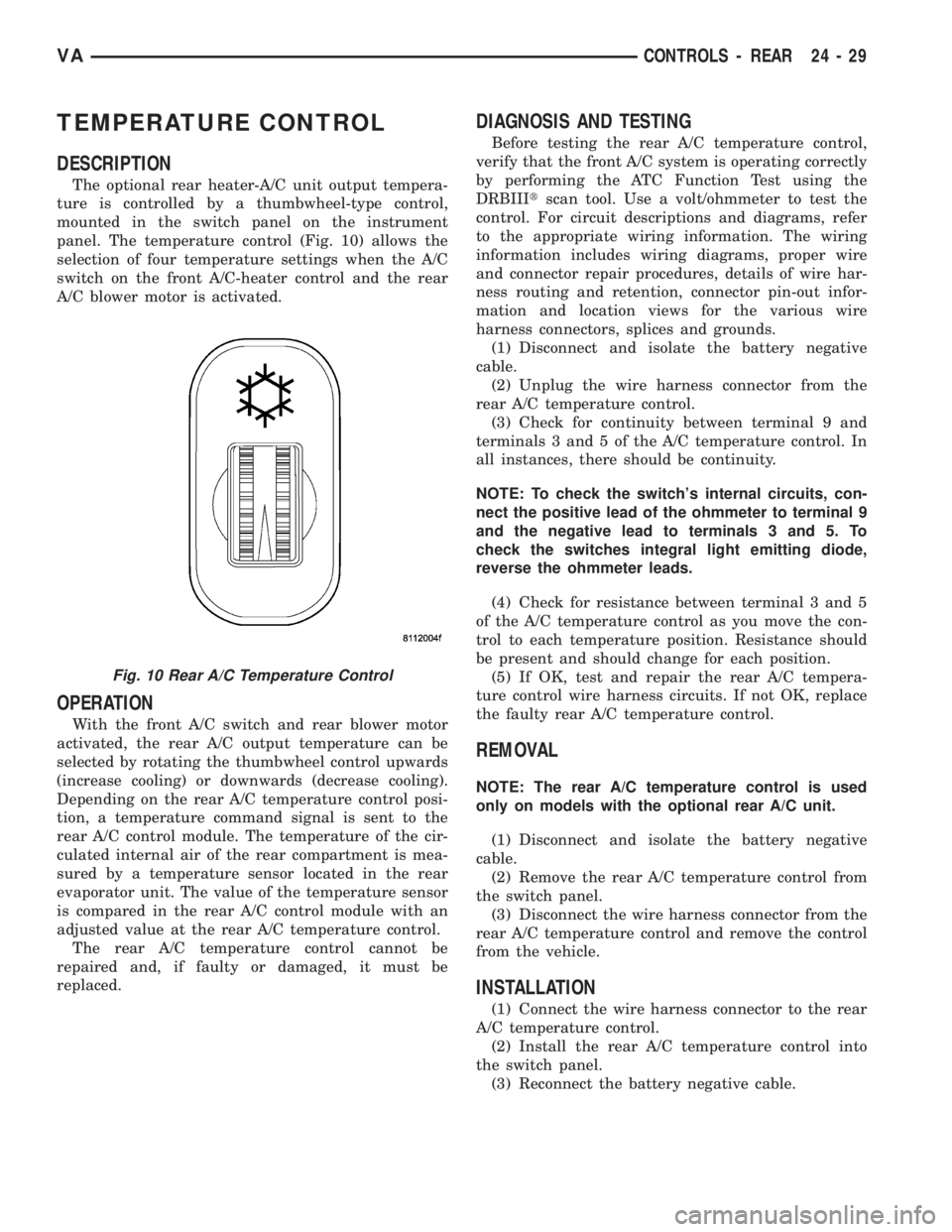
DESCRIPTION
The optional rear heater-A/C unit output tempera-
ture is controlled by a thumbwheel-type control,
mounted in the switch panel on the instrument
panel. The temperature control (Fig. 10) allows the
selection of four temperature settings when the A/C
switch on the front A/C-heater control and the rear
A/C blower motor is activated.
OPERATION
With the front A/C switch and rear blower motor
activated, the rear A/C output temperature can be
selected by rotating the thumbwheel control upwards
(increase cooling) or downwards (decrease cooling).
Depending on the rear A/C temperature control posi-
tion, a temperature command signal is sent to the
rear A/C control module. The temperature of the cir-
culated internal air of the rear compartment is mea-
sured by a temperature sensor located in the rear
evaporator unit. The value of the temperature sensor
is compared in the rear A/C control module with an
adjusted value at the rear A/C temperature control.
The rear A/C temperature control cannot be
repaired and, if faulty or damaged, it must be
replaced.
DIAGNOSIS AND TESTING
Before testing the rear A/C temperature control,
verify that the front A/C system is operating correctly
by performing the ATC Function Test using the
DRBIIItscan tool. Use a volt/ohmmeter to test the
control. For circuit descriptions and diagrams, refer
to the appropriate wiring information. The wiring
information includes wiring diagrams, proper wire
and connector repair procedures, details of wire har-
ness routing and retention, connector pin-out infor-
mation and location views for the various wire
harness connectors, splices and grounds.
(1) Disconnect and isolate the battery negative
cable.
(2) Unplug the wire harness connector from the
rear A/C temperature control.
(3) Check for continuity between terminal 9 and
terminals 3 and 5 of the A/C temperature control. In
all instances, there should be continuity.
NOTE: To check the switch's internal circuits, con-
nect the positive lead of the ohmmeter to terminal 9
and the negative lead to terminals 3 and 5. To
check the switches integral light emitting diode,
reverse the ohmmeter leads.
(4) Check for resistance between terminal 3 and 5
of the A/C temperature control as you move the con-
trol to each temperature position. Resistance should
be present and should change for each position.
(5) If OK, test and repair the rear A/C tempera-
ture control wire harness circuits. If not OK, replace
the faulty rear A/C temperature control.
REMOVAL
NOTE: The rear A/C temperature control is used
only on models with the optional rear A/C unit.
(1) Disconnect and isolate the battery negative
cable.
(2) Remove the rear A/C temperature control from
the switch panel.
(3) Disconnect the wire harness connector from the
rear A/C temperature control and remove the control
from the vehicle.
INSTALLATION
(1) Connect the wire harness connector to the rear
A/C temperature control.
(2) Install the rear A/C temperature control into
the switch panel.
(3) Reconnect the battery negative cable.
Fig. 10 Rear A/C Temperature Control
VACONTROLS - REAR 24 - 29
Page 1162 of 1232
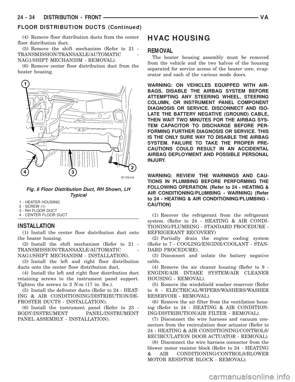
(4) Remove floor distribution ducts from the center
floor distribution duct.
(5) Remove the shift mechanism (Refer to 21 -
TRANSMISSION/TRANSAXLE/AUTOMATIC -
NAG1/SHIFT MECHANISM - REMOVAL).
(6) Remove center floor distribution duct from the
heater housing.
INSTALLATION
(1) Install the center floor distribution duct onto
the heater housing.
(2) Install the shift mechanism (Refer to 21 -
TRANSMISSION/TRANSAXLE/AUTOMATIC -
NAG1/SHIFT MECHANISM - INSTALLATION).
(3) Install the left and right floor distribution
ducts onto the center floor distribution duct.
(4) Install the left and right floor distribution duct
retaining screws to the instrument panel support.
Tighten the screws to 2 N´m (17 in. lbs.).
(5) Install the defroster ducts (Refer to 24 - HEAT-
ING & AIR CONDITIONING/DISTRIBUTION/DE-
FROSTER DUCTS - INSTALLATION).
(6) Install the instrument panel (Refer to 23 -
BODY/INSTRUMENT PANEL/INSTRUMENT
PANEL ASSEMBLY - INSTALLATION).
HVAC HOUSING
REMOVAL
The heater housing assembly must be removed
from the vehicle and the two halves of the housing
separated for service access of the heater core, evap-
orator and each of the various mode doors.
WARNING: ON VEHICLES EQUIPPED WITH AIR-
BAGS, DISABLE THE AIRBAG SYSTEM BEFORE
ATTEMPTING ANY STEERING WHEEL, STEERING
COLUMN, OR INSTRUMENT PANEL COMPONENT
DIAGNOSIS OR SERVICE. DISCONNECT AND ISO-
LATE THE BATTERY NEGATIVE (GROUND) CABLE,
THEN WAIT TWO MINUTES FOR THE AIRBAG SYS-
TEM CAPACITOR TO DISCHARGE BEFORE PER-
FORMING FURTHER DIAGNOSIS OR SERVICE. THIS
IS THE ONLY SURE WAY TO DISABLE THE AIRBAG
SYSTEM. FAILURE TO TAKE THE PROPER PRE-
CAUTIONS COULD RESULT IN AN ACCIDENTAL
AIRBAG DEPLOYMENT AND POSSIBLE PERSONAL
INJURY.
WARNING: REVIEW THE WARNINGS AND CAU-
TIONS IN PLUMBING BEFORE PERFORMING THE
FOLLOWING OPERATION. (Refer to 24 - HEATING &
AIR CONDITIONING/PLUMBING - WARNING) (Refer
to 24 - HEATING & AIR CONDITIONING/PLUMBING -
CAUTION)
(1) Recover the refrigerant from the refrigerant
system. (Refer to 24 - HEATING & AIR CONDI-
TIONING/PLUMBING - STANDARD PROCEDURE -
REFRIGERANT RECOVERY)
(2) Partially drain the engine cooling system
(Refer to 7 - COOLING/ENGINE/COOLANT - STAN-
DARD PROCEDURE).
(3) Disconnect and isolate the battery negative
cable.
(4) Remove the air cleaner housing (Refer to 9 -
ENGINE/AIR INTAKE SYSTEM/AIR CLEANER
HOUSING - REMOVAL).
(5) Remove the windshield washer reservoir (Refer
to 8 - ELECTRICAL/WIPERS/WASHERS/WASHER
RESERVOIR - REMOVAL).
(6) Remove the air filter from the ventilation hous-
ing (Refer to 24 - HEATING & AIR CONDITION-
ING/DISTRIBUTION/AIR FILTER - REMOVAL).
(7) Disconnect the wire harness and vacuum con-
nectors from the recirculation door actuator (Refer to
24 - HEATING & AIR CONDITIONING/CONTROLS/
RECIRCULATION DOOR ACTUATOR - REMOVAL).
(8) Disconnect the wire harness connector from the
blower motor resistor block (Refer to 24 - HEATING
& AIR CONDITIONING/CONTROLS/BLOWER
MOTOR RESISTOR BLOCK - REMOVAL).
Fig. 6 Floor Distribution Duct, RH Shown, LH
Typical
1 - HEATER HOUSING
2 - SCREW (1)
3 - RH FLOOR DUCT
4 - CENTER FLOOR DUCT
24 - 34 DISTRIBUTION - FRONTVA
FLOOR DISTRIBUTION DUCTS (Continued)
Page 1165 of 1232
(4) Connect the heater-A/C control cables to the
mode door levers (Refer to 24 - HEATING & AIR
CONDITIONING/CONTROLS/MODE DOOR CABLE
- INSTALLATION).
(5) Reinstall the passenger airbag bracket (Refer
to 8 - ELECTRICAL/RESTRAINTS/PASSENGER
AIRBAG - INSTALLATION).
(6) Reconnect the two bulkhead ground connection
near the instrument cluster area.
(7) Reinstall the defroster, floor distribution and
instrument panel ducts.
(8) Reinstall the instrument panel (Refer to 23 -
BODY/INSTRUMENT PANEL/INSTRUMENT
PANEL ASSEMBLY - INSTALLATION).
(9) Unplug or remove the tape from the opened
refrigerant line fittings.
(10) Lubricate two new rubber o-ring seals with
clean refrigerant oil and install them onto the evap-
orator core fittings.
(11) Connect the refrigerant line terminal block to
the evaporator tubes.
(12) Install the two bolts that secure the refriger-
ant line terminal block to the evaporator. Tighten the
bolts to 5 N´m (45 in. lbs.).
(13) Unplug or remove the tape from the heater
core hoses and tubes.
(14) Connect the heater hoses to the heater core
tubes and install the heater hose clamps.
(15) Install the ventilation housing to the dash
panel.
(16) Install the nuts and washers that secure the
ventilation housing to the dash panel. Tighten the
nuts to 5 N´m (45 in. lbs.).
(17) Connect the wire harness connectors to the
blower motor, blower motor resistor block and the
recirculation door actuator.
(18) Connect the vacuum harness connector to the
recirculation door actuator.
(19) Install the air filter into the ventilation hous-
ing (Refer to 24 - HEATING & AIR CONDITION-
ING/DISTRIBUTION/AIR FILTER -
INSTALLATION).
(20) Install the windshield washer reservoir (Refer
to 8 - ELECTRICAL/WIPERS/WASHERS/WASHER
RESERVOIR - INSTALLATION).
(21) Install the air cleaner housing (Refer to 9 -
ENGINE/AIR INTAKE SYSTEM/AIR CLEANER
HOUSING - INSTALLATION).
(22) Reconnect the battery negative cable.
(23) Refill the engine cooling system (Refer to 7 -
COOLING/ENGINE/COOLANT - STANDARD PRO-
CEDURE).
(24) Evacuate the refrigerant system (Refer to 24 -
HEATING & AIR CONDITIONING/PLUMBING -
STANDARD PROCEDURE - REFRIGERANT SYS-
TEM EVACUATE).(25) Charge the refrigerant system (Refer to 24 -
HEATING & AIR CONDITIONING/PLUMBING -
STANDARD PROCEDURE - REFRIGERANT SYS-
TEM CHARGE).
(26) Start the engine and check for proper opera-
tion of the heating and air conditioning systems.
INSTRUMENT PANEL DUCTS
REMOVAL
(1) Remove the instrument panel (Refer to 23 -
BODY/INSTRUMENT PANEL/INSTRUMENT
PANEL ASSEMBLY - REMOVAL).
(2) Remove the defroster ducts (Refer to 24 -
HEATING & AIR CONDITIONING/DISTRIBUTION/
DEFROSTER DUCTS - REMOVAL).
(3) Remove the floor distribution ducts (Refer to 24
- HEATING & AIR CONDITIONING/DISTRIBU-
TION/FLOOR DISTRIBUTION DUCTS - REMOV-
AL).
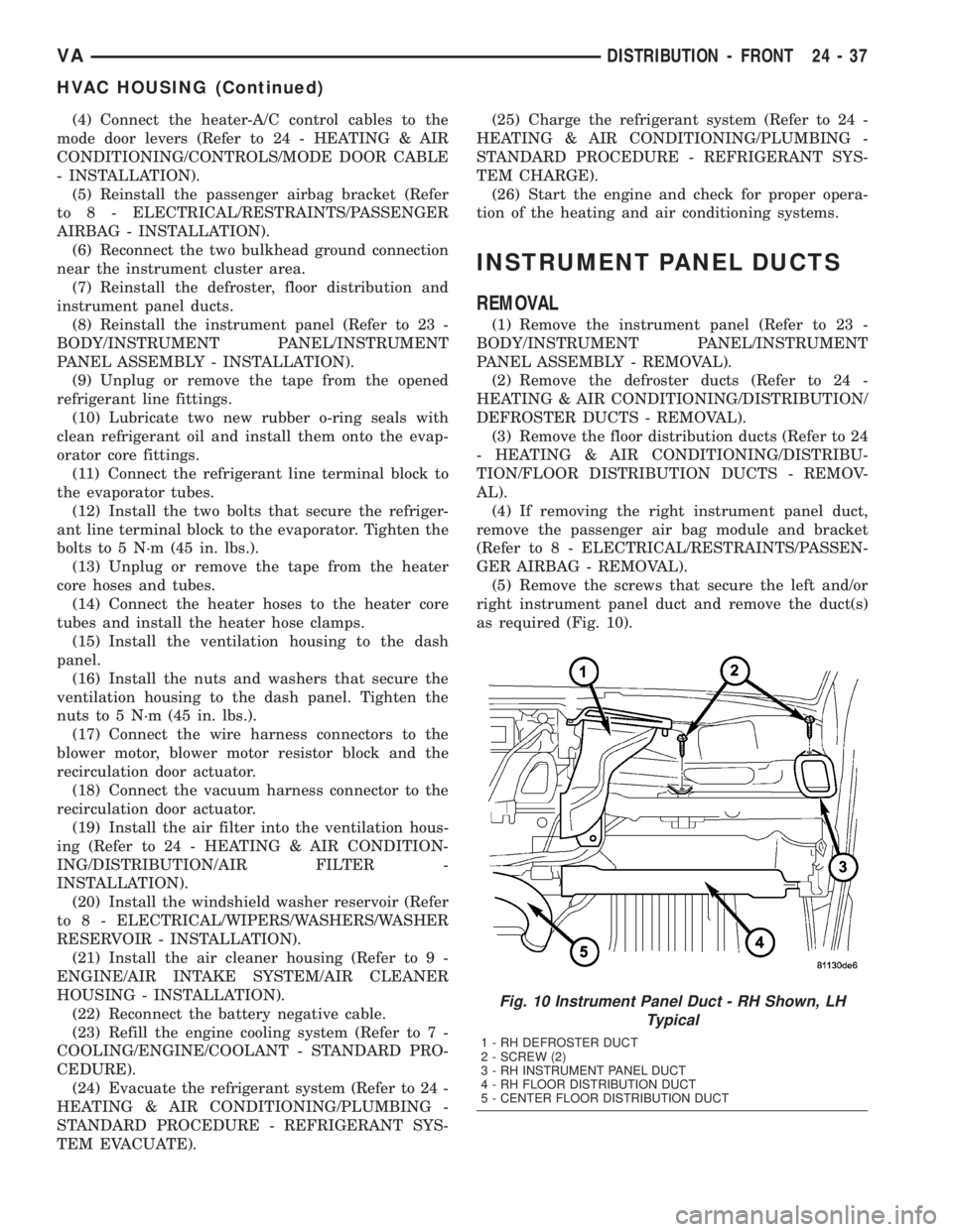
(4) If removing the right instrument panel duct,
remove the passenger air bag module and bracket
(Refer to 8 - ELECTRICAL/RESTRAINTS/PASSEN-
GER AIRBAG - REMOVAL).
(5) Remove the screws that secure the left and/or
right instrument panel duct and remove the duct(s)
as required (Fig. 10).
Fig. 10 Instrument Panel Duct - RH Shown, LH
Typical
1 - RH DEFROSTER DUCT
2 - SCREW (2)
3 - RH INSTRUMENT PANEL DUCT
4 - RH FLOOR DISTRIBUTION DUCT
5 - CENTER FLOOR DISTRIBUTION DUCT
VADISTRIBUTION - FRONT 24 - 37
HVAC HOUSING (Continued)