2005 MERCEDES-BENZ SPRINTER cooling
[x] Cancel search: coolingPage 1174 of 1232
When it is necessary to open the refrigerant sys-
tem, have everything needed to service the system
ready. The refrigerant system should not be left open
to the atmosphere any longer than necessary. Cap or
plug all lines and fittings as soon as they are opened
to prevent the entrance of dirt and moisture. All lines
and components in parts stock should be capped or
sealed until they are to be installed.
All tools, including the refrigerant recycling equip-
ment, the manifold gauge set, and test hoses should
be kept clean and dry. All tools and equipment must
be designed for R-134a refrigerant.
DIAGNOSIS AND TESTING - REFRIGERANT
SYSTEM LEAKS
WARNING: REVIEW THE WARNINGS AND CAU-
TIONS IN THE FRONT OF THIS SECTION BEFORE
PERFORMING THE FOLLOWING OPERATION.
(Refer to 24 - HEATING & AIR CONDITIONING/
PLUMBING - WARNING) (Refer to 24 - HEATING &
AIR CONDITIONING/PLUMBING - CAUTION)
If the air conditioning system is not cooling prop-
erly, determine if the refrigerant system is fully-
charged. (Refer to 24 - HEATING & AIR
CONDITIONING - DIAGNOSIS AND TESTING -
A/C PERFORMANCE)
An electronic leak detector designed for R-134a
refrigerant is recommended for locating and confirm-
ing refrigerant system leaks. Refer to the operating
instructions supplied by the equipment manufacturer
for proper care and use of this equipment.
An oily residue on or near refrigerant system lines,
connector fittings, components, or component seals
can indicate the general location of a possible refrig-
erant leak. However, the exact leak location should
be confirmed with an electronic leak detector prior to
component repair or replacement.
To detect a leak in the refrigerant system, perform
one of the following procedures:
SYSTEM EMPTY
(1) Evacuate the refrigerant system. (Refer to 24 -
HEATING & AIR CONDITIONING/PLUMBING -
STANDARD PROCEDURE - REFRIGERANT SYS-
TEM EVACUATE)
(2) Connect and dispense 0.283 kilograms (0.625
pounds or 10 ounces) of R-134a refrigerant into the
evacuated refrigerant system. (Refer to 24 - HEAT-
ING & AIR CONDITIONING/PLUMBING - STAN-
DARD PROCEDURE - REFRIGERANT SYSTEM
CHARGE)
(3) Position the vehicle in a wind-free work area.
This will aid in detecting small leaks.(4) With the engine not running, use a electronic
R-134a leak detector and search for leaks. Because
R-134a refrigerant is heavier than air, the leak detec-
tor probe should be moved slowly along the bottom
side of all refrigerant lines, connector fittings and
components.
(5) To inspect the evaporator coil for leaks, insert
the electronic leak detector probe into the center
instrument panel outlet. Set the blower motor switch
to the lowest speed position, the A/C button in the
On position, and select the Recirculation Mode.
SYSTEM LOW
(1) Position the vehicle in a wind-free work area.
This will aid in detecting small leaks.
(2) Bring the refrigerant system up to operating
temperature and pressure. This is done by allowing
the engine to run with the air conditioning system
turned on for five minutes.
(3) With the engine not running, use a electronic
R-134a leak detector and search for leaks. Because
R-134a refrigerant is heavier than air, the leak detec-
tor probe should be moved slowly along the bottom
side of all refrigerant lines, connector fittings and
components.
(4) To inspect the evaporator coil for leaks, insert
the electronic leak detector probe into the center
instrument panel outlet. Set the blower motor switch
to the lowest speed position, the A/C button in the
On position, and select the Recirculation Mode.
STANDARD PROCEDURE
STANDARD PROCEDURE - REFRIGERANT
SYSTEM SERVICE EQUIPMENT
WARNING: EYE PROTECTION MUST BE WORN
WHEN SERVICING AN AIR CONDITIONING REFRIG-
ERANT SYSTEM. TURN OFF (ROTATE CLOCKWISE)
ALL VALVES ON THE EQUIPMENT BEING USED,
BEFORE CONNECTING TO OR DISCONNECTING
FROM THE REFRIGERANT SYSTEM. FAILURE TO
OBSERVE THESE WARNINGS MAY RESULT IN PER-
SONAL INJURY.
WARNING: REVIEW THE WARNINGS AND CAU-
TIONS IN THE FRONT OF THIS SECTION BEFORE
PERFORMING THE FOLLOWING OPERATION.
(Refer to 24 - HEATING & AIR CONDITIONING/
PLUMBING - WARNING) (Refer to 24 - HEATING &
AIR CONDITIONING/PLUMBING - CAUTION)
24 - 46 PLUMBINGVA
PLUMBING (Continued)
Page 1178 of 1232
Drive belts are speed sensitive. At different engine
speeds and depending upon belt tension, belts can
develop noises that are mistaken for a compressor
noise. Improper belt tension can cause a misleading
noise when the compressor clutch is engaged, which
may not occur when the compressor clutch is disen-
gaged. Check the serpentine drive belt condition and
tension as described in Cooling before beginning this
procedure.
(1) Select a quiet area for testing. Duplicate the
complaint conditions as much as possible. Switch the
compressor on and off several times to clearly iden-
tify the compressor noise. Listen to the compressor
while the clutch is engaged and disengaged. Probe
the compressor with an engine stethoscope or a long
screwdriver with the handle held to your ear to bet-
ter localize the source of the noise.
(2) Loosen all of the compressor mounting hard-
ware and retighten. Tighten the compressor clutch
mounting nut. Be certain that the clutch coil is
mounted securely to the compressor, and that the
clutch plate and pulley are properly aligned and have
the correct air gap. (Refer to 24 - HEATING & AIR
CONDITIONING/CONTROLS/A/C COMPRESSOR
CLUTCH - INSTALLATION)
(3) To duplicate a high-ambient temperature condi-
tion (high head pressure), restrict the air flow
through the condenser. Install a manifold gauge set
to be certain that the discharge pressure does not
exceed 2760 kPa (400 psi).
(4) Check the refrigerant system plumbing for
incorrect routing, rubbing or interference, which can
cause unusual noises. Also check the refrigerant lines
for kinks or sharp bends that will restrict refrigerant
flow, which can cause noises. (Refer to 24 - HEAT-
ING & AIR CONDITIONING/PLUMBING - CAU-
TION - REFRIGERANT HOSES/LINES/TUBES
PRECAUTIONS)
(5) If the noise is from opening and closing of the
high pressure relief valve, reclaim, evacuate, and
recharge the refrigerant system. (Refer to 24 - HEAT-
ING & AIR CONDITIONING/PLUMBING - STAN-
DARD PROCEDURE - REFRIGERANT RECOVERY)
(Refer to 24 - HEATING & AIR CONDITIONING/
PLUMBING - STANDARD PROCEDURE - REFRIG-
ERANT SYSTEM EVACUATE) (Refer to 24 -
HEATING & AIR CONDITIONING/PLUMBING -
STANDARD PROCEDURE - REFRIGERANT SYS-
TEM CHARGE)If the high pressure relief valve still
does not seat properly, replace the a/c compressor.
(Refer to 24 - HEATING & AIR CONDITIONING/
PLUMBING/A/C COMPRESSOR - REMOVAL)
(6) If the noise is from liquid slugging on the suc-
tion line, check the refrigerant oil level and the
refrigerant system charge. (Refer to 24 - HEATING
& AIR CONDITIONING/PLUMBING/REFRIGER-ANT OIL - STANDARD PROCEDURE) (Refer to 24 -
HEATING & AIR CONDITIONING/PLUMBING -
SPECIFICATIONS - CHARGE CAPACITY).
(7) If the noise continues, replace the compressor
and repeat Step 1.
REMOVAL
WARNING: REVIEW THE WARNINGS AND CAU-
TIONS IN THE FRONT OF THIS SECTION BEFORE
PERFORMING THE FOLLOWING OPERATION (Refer
to 24 - HEATING & AIR CONDITIONING/PLUMBING -
WARNING) and (Refer to 24 - HEATING & AIR CON-
DITIONING/PLUMBING - CAUTION).
(1) Disconnect the negative battery cable.
(2) Recover the refrigerant from the refrigerant
system (Refer to 24 - HEATING & AIR CONDITION-
ING/PLUMBING - STANDARD PROCEDURE -
REFRIGERANT RECOVERY).
(3) Remove the accessory drive belt from the com-
pressor clutch (Fig. 2).
(4) Remove the bolt that secures the suction line
fitting to the top of the compressor.
(5) Disconnect the suction line fitting from the
compressor suction port.
(6) Remove the seal from the suction line fitting
and discard.
(7) Install plugs in, or tape over the opened suc-
tion line fitting and the compressor suction port.
(8) Remove the bolt that secures the discharge line
fitting to the top of the compressor.
(9) Disconnect the discharge line fitting from the
compressor discharge port.
(10) Remove the seal from the discharge line fit-
ting and discard.
(11) Install plugs in, or tape over the opened dis-
charge line fitting and the compressor discharge port.
(12) Disconnect the engine wire harness connector
for the compressor clutch coil from the coil pigtail
wire connector on the top of the compressor.
(13) Raise the vehicle on a hoist.
(14) Support the compressor and remove the three
compressor mounting bolts.
(15) Remove the compressor from the engine com-
partment.
NOTE: If a replacement compressor is being
installed, be certain to drain and measure the refrig-
erant oil contained in the removed compressor.
This will determine how much oil the replacement
compressor must contain before it is installed
(Refer to 24 - HEATING & AIR CONDITIONING/
PLUMBING/REFRIGERANT OIL - STANDARD PRO-
CEDURE).
24 - 50 PLUMBINGVA
A/C COMPRESSOR (Continued)
Page 1180 of 1232
(6) Connect the discharge line fitting to the com-
pressor discharge port.
(7) Install the bolt that secures the discharge line
fitting to the top of the compressor. Tighten the bolt
to 23 N´m (17 ft. lbs.).
(8) Remove plugs or tape from the suction line fit-
ting and the compressor suction port.
(9) Lubricate a new rubber o-ring seal with clean
refrigerant oil and install the seal onto the suction
line fitting.
(10) Connect the suction line fitting to the com-
pressor suction port.
(11) Install the bolt that secures the suction line
fitting to the top of the compressor. Tighten the bolt
to 23 N´m (17 ft. lbs.).
(12) Install the accessory drive belt (Refer to 7 -
COOLING/ACCESSORY DRIVE/DRIVE BELTS -
INSTALLATION).
(13) Reconnect the negative battery cable.
(14) Evacuate the refrigerant system (Refer to 24 -
HEATING & AIR CONDITIONING/PLUMBING -
STANDARD PROCEDURE - REFRIGERANT SYS-
TEM EVACUATE).
(15) Charge the refrigerant system (Refer to 24 -
HEATING & AIR CONDITIONING/PLUMBING -
STANDARD PROCEDURE - REFRIGERANT SYS-
TEM CHARGE).
A/C CONDENSER
DESCRIPTION
The condenser is located in the air flow in front of
the engine cooling radiator. The condenser is a heat
exchanger that allows the high-pressure refrigerant
gas being discharged by the compressor to give up its
heat to the air passing over the condenser fins.
OPERATION
When the refrigerant gas gives up its heat, it con-
denses. When the refrigerant leaves the condenser, it
has become a high-pressure liquid refrigerant. The
volume of air flowing over the condenser fins is crit-
ical to the proper cooling performance of the air con-
ditioning system. Therefore, it is important that
there are no objects placed in front of the radiator
grille openings in the front of the vehicle or foreign
material on the condenser fins that might obstruct
proper air flow. Also, any factory-installed air seals or
shrouds must be properly reinstalled following radia-
tor or condenser service.
The condenser cannot be repaired and, if faulty or
damaged, it must be replaced.
REMOVAL
WARNING: REVIEW THE WARNINGS AND CAU-
TIONS IN THE FRONT OF THIS SECTION BEFORE
PERFORMING THE FOLLOWING OPERATION (Refer
to 24 - HEATING & AIR CONDITIONING/PLUMBING -
WARNING) and (Refer to 24 - HEATING & AIR CON-
DITIONING/PLUMBING - CAUTION).
(1) Disconnect and isolate the battery negative
cable.
(2) Recover the refrigerant from the refrigerant
system (Refer to 24 - HEATING & AIR CONDITION-
ING/PLUMBING - STANDARD PROCEDURE -
REFRIGERANT RECOVERY).
(3) Remove the front fascia.
(4) Remove the grille (Refer to 23 - BODY/EXTE-
RIOR/GRILLE - REMOVAL).
(5) Remove the headlamps from their mounts.
(6) Remove the radiator crossmember (Refer to 23
- BODY/EXTERIOR/RADIATOR CROSSMEMBER -
REMOVAL).
(7) Disconnect the liquid line fitting from the con-
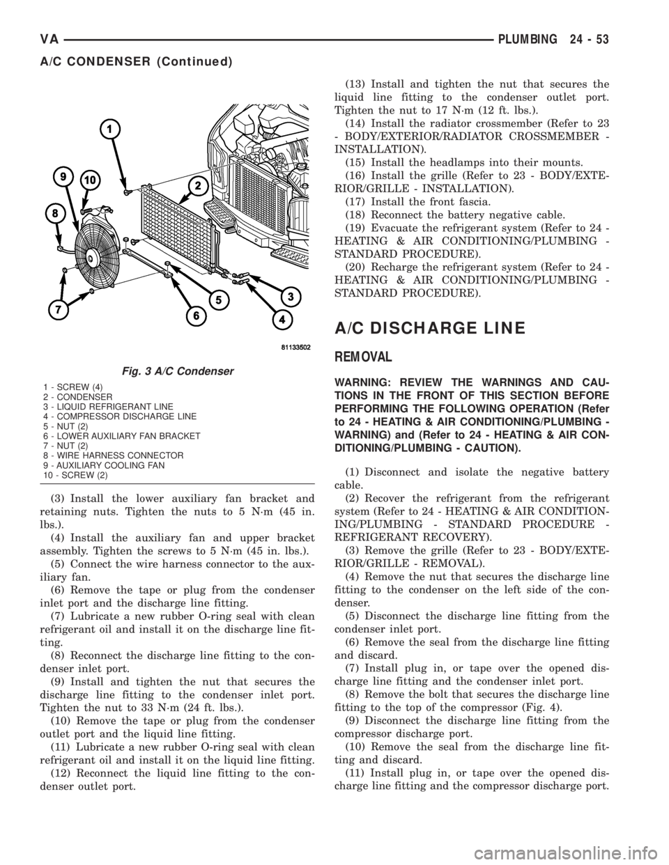
denser outlet port (Fig. 3).
(8) Remove the seal from the liquid line fitting and
discard.
(9) Install plug in, or tape over the opened liquid
line fitting and the condenser outlet port.
(10) Disconnect the discharge line fitting from the
condenser inlet port.
(11) Remove the seal from the discharge line fit-
ting and discard.
(12) Install plug in, or tape over the opened dis-
charge line fitting and the condenser inlet port.
(13) Disconnect the wire harness connector from
the auxiliary fan.
(14) Remove the auxiliary fan and upper bracket
assembly.
(15) Remove the auxiliary fan lower bracket
retainers and bracket.
(16) Remove the four condenser retaining screws.
(17) Carefully remove the condenser from the vehi-
cle.
INSTALLATION
NOTE: If the condenser is being replaced, add 30
milliliters (1 fluid ounce) of refrigerant oil to the
refrigerant system. Use only refrigerant oil of the
type recommended for the compressor in the vehi-
cle.
(1) Carefully position the condenser in the vehicle.
(2) Install the four condenser retaining screws.
Tighten the screws to 2 N´m (17 in. lbs.).
24 - 52 PLUMBINGVA
A/C COMPRESSOR (Continued)
Page 1181 of 1232
(3) Install the lower auxiliary fan bracket and
retaining nuts. Tighten the nuts to 5 N´m (45 in.
lbs.).
(4) Install the auxiliary fan and upper bracket
assembly. Tighten the screws to 5 N´m (45 in. lbs.).
(5) Connect the wire harness connector to the aux-
iliary fan.
(6) Remove the tape or plug from the condenser
inlet port and the discharge line fitting.
(7) Lubricate a new rubber O-ring seal with clean
refrigerant oil and install it on the discharge line fit-
ting.
(8) Reconnect the discharge line fitting to the con-
denser inlet port.
(9) Install and tighten the nut that secures the
discharge line fitting to the condenser inlet port.
Tighten the nut to 33 N´m (24 ft. lbs.).
(10) Remove the tape or plug from the condenser
outlet port and the liquid line fitting.
(11) Lubricate a new rubber O-ring seal with clean
refrigerant oil and install it on the liquid line fitting.
(12) Reconnect the liquid line fitting to the con-
denser outlet port.(13) Install and tighten the nut that secures the
liquid line fitting to the condenser outlet port.
Tighten the nut to 17 N´m (12 ft. lbs.).
(14) Install the radiator crossmember (Refer to 23
- BODY/EXTERIOR/RADIATOR CROSSMEMBER -
INSTALLATION).
(15) Install the headlamps into their mounts.
(16) Install the grille (Refer to 23 - BODY/EXTE-
RIOR/GRILLE - INSTALLATION).
(17) Install the front fascia.
(18) Reconnect the battery negative cable.
(19) Evacuate the refrigerant system (Refer to 24 -
HEATING & AIR CONDITIONING/PLUMBING -
STANDARD PROCEDURE).
(20) Recharge the refrigerant system (Refer to 24 -
HEATING & AIR CONDITIONING/PLUMBING -
STANDARD PROCEDURE).
A/C DISCHARGE LINE
REMOVAL
WARNING: REVIEW THE WARNINGS AND CAU-
TIONS IN THE FRONT OF THIS SECTION BEFORE
PERFORMING THE FOLLOWING OPERATION (Refer
to 24 - HEATING & AIR CONDITIONING/PLUMBING -
WARNING) and (Refer to 24 - HEATING & AIR CON-
DITIONING/PLUMBING - CAUTION).
(1) Disconnect and isolate the negative battery
cable.
(2) Recover the refrigerant from the refrigerant
system (Refer to 24 - HEATING & AIR CONDITION-
ING/PLUMBING - STANDARD PROCEDURE -
REFRIGERANT RECOVERY).
(3) Remove the grille (Refer to 23 - BODY/EXTE-
RIOR/GRILLE - REMOVAL).
(4) Remove the nut that secures the discharge line
fitting to the condenser on the left side of the con-
denser.
(5) Disconnect the discharge line fitting from the
condenser inlet port.
(6) Remove the seal from the discharge line fitting
and discard.
(7) Install plug in, or tape over the opened dis-
charge line fitting and the condenser inlet port.
(8) Remove the bolt that secures the discharge line
fitting to the top of the compressor (Fig. 4).
(9) Disconnect the discharge line fitting from the
compressor discharge port.
(10) Remove the seal from the discharge line fit-
ting and discard.
(11) Install plug in, or tape over the opened dis-
charge line fitting and the compressor discharge port.
Fig. 3 A/C Condenser
1 - SCREW (4)
2 - CONDENSER
3 - LIQUID REFRIGERANT LINE
4 - COMPRESSOR DISCHARGE LINE
5 - NUT (2)
6 - LOWER AUXILIARY FAN BRACKET
7 - NUT (2)
8 - WIRE HARNESS CONNECTOR
9 - AUXILIARY COOLING FAN
10 - SCREW (2)
VAPLUMBING 24 - 53
A/C CONDENSER (Continued)
Page 1183 of 1232
REMOVAL
WARNING: ON VEHICLES EQUIPPED WITH AIR-
BAGS, DISABLE THE AIRBAG SYSTEM BEFORE
ATTEMPTING ANY STEERING WHEEL, STEERING
COLUMN, OR INSTRUMENT PANEL COMPONENT
DIAGNOSIS OR SERVICE. DISCONNECT AND ISO-
LATE THE BATTERY NEGATIVE (GROUND) CABLE,
THEN WAIT TWO MINUTES FOR THE AIRBAG SYS-
TEM CAPACITOR TO DISCHARGE BEFORE PER-
FORMING FURTHER DIAGNOSIS OR SERVICE. THIS
IS THE ONLY SURE WAY TO DISABLE THE AIRBAG
SYSTEM. FAILURE TO TAKE THE PROPER PRE-
CAUTIONS COULD RESULT IN AN ACCIDENTAL
AIRBAG DEPLOYMENT AND POSSIBLE PERSONAL
INJURY.
WARNING: REVIEW THE WARNINGS AND CAU-
TIONS IN THE FRONT OF THIS SECTION BEFORE
PERFORMING THE FOLLOWING OPERATION (Refer
to 24 - HEATING & AIR CONDITIONING/PLUMBING -
WARNING) and (Refer to 24 - HEATING & AIR CON-
DITIONING/PLUMBING - CAUTION).
(1) Remove the heater housing (Refer to 24 -
HEATING & AIR CONDITIONING/DISTRIBUTION/
HVAC HOUSING - REMOVAL).
(2) Disassemble the heater housing to access the
evaporator (Refer to 24 - HEATING & AIR CONDI-
TIONING/DISTRIBUTION/HVAC HOUSING - DIS-
ASSEMBLY).
(3) Lift the evaporator out of the lower half of the
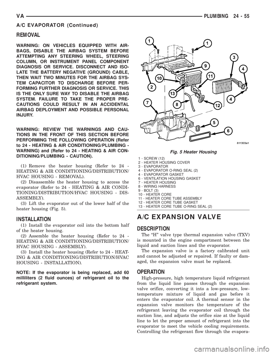
heater housing (Fig. 5).
INSTALLATION
(1) Install the evaporator coil into the bottom half
of the heater housing.
(2) Assemble the heater housing (Refer to 24 -
HEATING & AIR CONDITIONING/DISTRIBUTION/
HVAC HOUSING - ASSEMBLY).
(3) Install the heater housing (Refer to 24 - HEAT-
ING & AIR CONDITIONING/DISTRIBUTION/HVAC
HOUSING - INSTALLATION).
NOTE: If the evaporator is being replaced, add 60
milliliters (2 fluid ounces) of refrigerant oil to the
refrigerant system.
A/C EXPANSION VALVE
DESCRIPTION
The ªHº valve type thermal expansion valve (TXV)
is mounted in the engine compartment between the
liquid and suction lines and the evaporator.
The expansion valve is a factory calibrated unit
and cannot be adjusted or repaired. If faulty or dam-
aged, the expansion valve must be replaced.
OPERATION
High-pressure, high temperature liquid refrigerant
from the liquid line passes through the expansion
valve orifice, converting it into a low-pressure, low-
temperature mixture of liquid and gas before it
enters the evaporator coil. A thermal sensor in the
expansion valve monitors the temperature of the
refrigerant leaving the evaporator coil through the
suction line, and adjusts the orifice size at the liquid
line to let the proper amount of refrigerant into the
evaporator to meet the vehicle cooling requirements.
Controlling the refrigerant flow through the evapora-
Fig. 5 Heater Housing
1 - SCREW (12)
2 - HEATER HOUSING COVER
3 - EVAPORATOR
4 - EVAPORATOR O-RING SEAL (2)
4 - EVAPORATOR GASKET
6 - VENTILATION HOUSING GASKET
7 - HEATER HOUSING
8 - WIRING HARNESS
9 - BOLT (3)
10 - HEATER CORE
11 - HEATER CORE TUBE ASSEMBLY
12 - HEATER CORE TUBE GASKET
13 - HEATER CORE TUBE O-RING SEAL (2)
VAPLUMBING 24 - 55
A/C EVAPORATOR (Continued)
Page 1184 of 1232
tor ensures that none of the refrigerant leaving the
evaporator is still in a liquid state, which could cause
damage to the compressor.
DIAGNOSIS AND TESTING - A/C EXPANSION
VALVE
The expansion valve is located on the engine side
of the dash panel near the shock tower.
The expansion valve can fail in three different
positions (open, closed or restricted).
In an Open Position: this will result in a noisy
compressor or no cooling. The cause can be broken
spring, broken ball or excessive moisture in the A/C
system. If the spring or ball are found to be defective,
replace the expansion valve. If excessive moisture is
found in the A/C system, recycle the refrigerant.
In a Closed Position: There will be low suction
pressure and no cooling. This may be caused by a
failed power dome or excessive moisture in the A/C
system. If the power dome on the expansion valve is
found to be defective replace the expansion valve. If
excessive moisture is found recycle the refrigerant.
A Restricted Orifice: There will be low suction
pressure and no cooling. This may be caused by
debris in the refrigerant system. If debris is believed
to be the cause, recycle the refrigerant and replace
the expansion valve and the receiver-drier.
REMOVAL
WARNING: REFER TO THE APPLICABLE WARN-
INGS AND CAUTIONS FOR THIS SYSTEM BEFORE
PERFORMING THE FOLLOWING OPERATION (Refer
to 24 - HEATING & AIR CONDITIONING/PLUMBING -
WARNING) and (Refer to 24 - HEATING & AIR CON-
DITIONING/PLUMBING - CAUTION).
(1) Recover the refrigerant from the A/C system-
(Refer to 24 - HEATING & AIR CONDITIONING/
PLUMBING - STANDARD PROCEDURE).
(2) Disconnect and isolate the battery negative
cable.
(3) Remove the nut that secures the suction and
liquid line fittings to the stud on the expansion valve
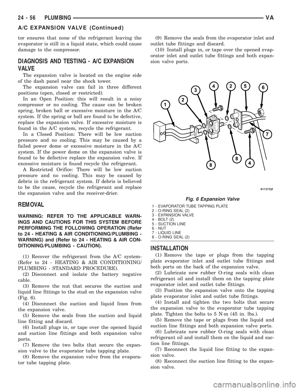
(Fig. 6).
(4) Disconnect the suction and liquid lines from
the expansion valve.
(5) Remove the seals from the suction and liquid
line fitting and discard.
(6) Install plugs in, or tape over the opened liquid
and suction line fittings and both expansion valve
ports.
(7) Remove the two bolts that secure the expan-
sion valve to the evaporator tube tapping plate.
(8) Remove the expansion valve from the evapora-
tor tube tapping plate.(9) Remove the seals from the evaporator inlet and
outlet tube fittings and discard.
(10) Install plugs in, or tape over the opened evap-
orator inlet and outlet tube fittings and both expan-
sion valve ports.
INSTALLATION
(1) Remove the tape or plugs from the tapping
plate evaporator inlet and outlet tube fittings and
both ports on the back of the expansion valve.
(2) Lubricate new rubber O-ring seals with clean
refrigerant oil and install them on the tapping plate
evaporator inlet and outlet tube fittings.
(3) Position the expansion valve onto the tapping
plate evaporator inlet and outlet tube fittings.
(4) Install and tighten the two bolts that secure
the expansion valve to the evaporator tube tapping
plate. Tighten the bolts to 5 N´m (45 in. lbs.).
(5) Remove the tape or plugs from the liquid and
suction line fittings and both expansion valve ports.
(6) Lubricate new rubber O-ring seals with clean
refrigerant oil and install them on the liquid and suc-
tion line fittings.
(7) Reconnect the liquid line fitting to the expan-
sion valve.
(8) Reconnect the suction line fitting to the expan-
sion valve.
Fig. 6 Expansion Valve
1 - EVAPORATOR TUBE TAPPING PLATE
2 - O-RING SEAL (2)
3 - EXPANSION VALVE
4 - BOLT (2)
5 - SUCTION LINE
6 - NUT
7 - LIQUID LINE
8 - O-RING SEAL (2)
24 - 56 PLUMBINGVA
A/C EXPANSION VALVE (Continued)
Page 1185 of 1232
(9) Install and tighten the nut that secures the
suction line and liquid line fittings to the stud on the
expansion valve. Tighten the nut to 10 N´m (89 in.
lbs.).
(10) Reconnect the battery negative cable.
(11) Evacuate the refrigerant system (Refer to 24 -
HEATING & AIR CONDITIONING/PLUMBING -
STANDARD PROCEDURE).
(12) Charge the refrigerant system (Refer to 24 -
HEATING & AIR CONDITIONING/PLUMBING -
STANDARD PROCEDURE).
ELECTRIC COOLANT PUMP
DESCRIPTION
The electric coolant pump is used on all vehicles.
The pump is located in the left side of the engine
compartment near the battery.
OPERATION
The pump is controlled by the ATC control module
and is only operational under the following condi-
tions:
(1) Vehicle speed below 27 Km/h (17 mph).
(2) Coolant temperature above 65É C (150É F) but
less than 110É C (230 É F).
(3) Any blower speed setting.
(4) Temperature heat setting above the halfway
setting (60% heat).
(5) The pump will turn off at speeds above 48
Km/h (30 mph).
(6) The pump will turn off if the coolant tempera-
ture rises above 110É C (230 É F).
REMOVAL
(1) Disconnect and isolate the battery negative
cable.
(2) Partially drain the engine cooling system
(Refer to 7 - COOLING/ENGINE/COOLANT - STAN-
DARD PROCEDURE).
(3) Disconnect the wire harness connector from the
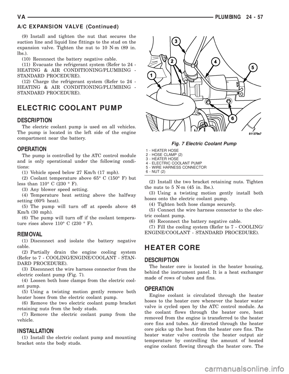
electric coolant pump (Fig. 7).
(4) Loosen both hose clamps from the electric cool-
ant pump.
(5) Using a twisting motion gently remove both
heater hoses from the electric coolant pump.
(6) Remove the two electric coolant pump bracket
retaining nuts from the body studs.
(7) Remove the electric coolant pump from the
vehicle.
INSTALLATION
(1) Install the electric coolant pump and mounting
bracket onto the body studs.(2) Install the two bracket retaining nuts. Tighten
the nuts to 5 N´m (45 in. lbs.).
(3) Using a twisting motion gently install both
hoses onto the electric coolant pump.
(4) Tighten both hose clamps securely.
(5) Connect the wire harness connector to the elec-
tric coolant pump.
(6) Reconnect the battery negative cable.
(7) Fill the cooling system (Refer to 7 - COOLING/
ENGINE/COOLANT - STANDARD PROCEDURE).
HEATER CORE
DESCRIPTION
The heater core is located in the heater housing,
behind the instrument panel. It is a heat exchanger
made of rows of tubes and fins.
OPERATION
Engine coolant is circulated through the heater
hoses to the heater core whenever the heater water
valve is cycled open by the ATC control module. As
the coolant flows through the heater core, heat
removed from the engine is transferred to the heater
core fins and tubes. Air directed through the heater
core picks up the heat from the heater core fins. The
heater water valve controls the heater output air
temperature by controlling the amount of heated
engine coolant flowing through the heater core. The
Fig. 7 Electric Coolant Pump
1 - HEATER HOSE
2 - HOSE CLAMP (2)
3 - HEATER HOSE
4 - ELECTRIC COOLANT PUMP
5 - WIRE HARNESS CONNECTOR
6 - NUT (2)
VAPLUMBING 24 - 57
A/C EXPANSION VALVE (Continued)
Page 1193 of 1232
REFRIGERANT
DESCRIPTION
The refrigerant used in this air conditioning sys-
tem is a HydroFluoroCarbon (HFC), type R-134a.
Unlike R-12, which is a ChloroFluoroCarbon (CFC),
R-134a refrigerant does not contain ozone-depleting
chlorine. R-134a refrigerant is a non-toxic, non-flam-
mable, clear, and colorless liquefied gas.
Even though R-134a does not contain chlorine, it
must be reclaimed and recycled just like CFC-type
refrigerants. This is because R-134a is a greenhouse
gas and can contribute to global warming.
OPERATION
R-134a refrigerant is not compatible with R-12
refrigerant in an air conditioning system. Even a
small amount of R-12 added to an R-134a refrigerant
system will cause compressor failure, refrigerant oil
sludge or poor air conditioning system performance.
In addition, the PolyAlkylene Glycol (PAG) synthetic
refrigerant oils used in an R-134a refrigerant system
are not compatible with the mineral-based refriger-
ant oils used in an R-12 refrigerant system.
R-134a refrigerant system service ports, service
tool couplers and refrigerant dispensing bottles have
all been designed with unique fittings to ensure that
an R-134a system is not accidentally contaminated
with the wrong refrigerant (R-12). There are also
labels posted in the engine compartment of the vehi-
cle and on the compressor identifying to service tech-
nicians that the air conditioning system is equipped
with R-134a.
REFRIGERANT OIL
DESCRIPTION
The refrigerant oil used in R-134a refrigerant sys-
tems is a synthetic-based, PolyAlkylene Glycol (PAG),
wax-free lubricant. Mineral-based R-12 refrigerant
oils are not compatible with PAG oils, and should
never be introduced to an R-134a refrigerant system.
There are different PAG oils available, and each
contains a different additive package. The 10PA17
compressor used in this vehicle is designed to use an
ND8 PAG refrigerant oil. Use only refrigerant oil of
this same type to service the refrigerant system.
OPERATION
After performing any refrigerant recovery or recy-
cling operation, always replenish the refrigerant sys-
tem with the same amount of the recommended
refrigerant oil as was removed. Too little refrigerant
oil can cause compressor damage, and too much can
reduce air conditioning system performance.
PAG refrigerant oil is much more hygroscopic than
mineral oil, and will absorb any moisture it comes
into contact with, even moisture in the air. The PAG
oil container should always be kept tightly capped
until it is ready to be used. After use, recap the oil
container immediately to prevent moisture contami-
nation.
STANDARD PROCEDURE - REFRIGERANT OIL
LEVEL
When an air conditioning system is assembled at
the factory, all components except the compressor are
refrigerant oil free. After the refrigerant system has
been charged and operated, the refrigerant oil in the
compressor is dispersed throughout the refrigerant
system. The receiver-drier, evaporator, condenser,
and compressor will each retain a significant amount
of the needed refrigerant oil.
It is important to have the correct amount of oil in
the refrigerant system. This ensures proper lubrica-
tion of the compressor. Too little oil will result in
damage to the compressor. Too much oil will reduce
the cooling capacity of the air conditioning system.
It will not be necessary to check the oil level in the
compressor or to add oil, unless there has been an oil
loss. An oil loss may occur due to a rupture or leak
from a refrigerant line, a connector fitting, a compo-
nent, or a component seal. If a leak occurs, add 30
milliliters (1 fluid ounce) of refrigerant oil to the
refrigerant system after the repair has been made.
Refrigerant oil loss will be evident at the leak point
by the presence of a wet, shiny surface around the
leak.
Refrigerant oil must be added when a receiver/
drier, evaporator coil, or condenser are replaced. See
the Refrigerant Oil Capacities chart. When a com-
pressor is replaced, the refrigerant oil must be
drained from the old compressor and measured.
Drain all of the refrigerant oil from the new compres-
sor, then fill the new compressor with the same
amount of refrigerant oil that was drained out of the
old compressor.
VAPLUMBING 24 - 65