2004 SUBARU FORESTER oil filter
[x] Cancel search: oil filterPage 2313 of 2870

AUTOMATIC TRANSMISSION
4AT
Page
1. General Description ....................................................................................2
2. Automatic Transmission Fluid ...................................................................30
3. Differential Gear Oil...................................................................................31
4. Road Test..................................................................................................32
5. Stall Test ...................................................................................................33
6. Time Lag Test ...........................................................................................35
7. Line Pressure Test ....................................................................................36
8. Transfer Clutch Pressure Test ..................................................................38
9. Automatic Transmission Assembly ...........................................................39
10. Transmission Mounting System ................................................................47
11. Extension Case Oil Seal ...........................................................................49
12. Differential Side Retainer Oil Seal.............................................................50
13. Inhibitor Switch ..........................................................................................51
14. Front Vehicle Speed Sensor .....................................................................55
15. Rear Vehicle Speed Sensor ......................................................................59
16. Torque Converter Turbine Speed Sensor .................................................60
17. Control Valve Body ...................................................................................61
18. Air Bleeding of Control Valve ....................................................................70
19.
Shift Solenoids, Duty Solenoids and ATF Temperature Sensor.........................71
20. Transfer Duty Solenoid and Valve Body ...................................................73
21. ATF Filter ..................................................................................................76
22. Transmission Control Module (TCM) ........................................................77
23. Dropping Resistor .....................................................................................78
24. ATF Cooler Pipe and Hose .......................................................................79
25. ATF Cooler (With Warmer Function).........................................................84
26. Air Breather Hose......................................................................................87
27. Oil Charger Pipe........................................................................................88
28. Torque Converter Clutch Assembly ..........................................................89
29. Extension Case .........................................................................................90
30. Transfer Clutch..........................................................................................92
31. Reduction Driven Gear..............................................................................97
32. Reduction Drive Gear................................................................................99
33. Parking Pawl ...........................................................................................101
34. Torque Converter Clutch Case ...............................................................102
35. Oil Pump Housing ...................................................................................105
36. Drive Pinion Shaft Assembly ...................................................................111
37. Front Differential......................................................................................117
38. AT Main Case .........................................................................................123
39. Transmission Control Device ..................................................................142
Page 2320 of 2870

4AT-8
AUTOMATIC TRANSMISSION
General Description
(1) ATF level gauge (19) Oil filter (41) Transmission case
(2) ATF charger pipe (20) Oil filter stud bolt (42) Plate ASSY
(3) O-ring (21) Drain plug (ATF) (43) Washer
(4) Transfer valve plate (22) Gasket (44) Bushing (turbo model)
(Non-turbo model) (23) Oil pan (45) ATF cooler inlet pipe (model with
ATF cooler (with warmer func-
tion)) (5) Transfer valve ASSY (24) Magnet
(Non-turbo model) (25) Stud bolt (Short)
(6) Transfer clutch seal
(Non-turbo model)(26) Stud bolt (Long) (46) ATF cooler outlet pipe (model
with ATF cooler (with warmer
function)) (27) Parking rod
(7) Transfer duty solenoid (non-turbo
model)(28) Manual plate
(29) Spring pin
(8) Straight pin (30) Detention springTightening torque: N
⋅m (kgf-m, ft-lb)
(9) Return spring (31) BallT1: 3.4 (0.35, 2.6)
(10) Shaft (32) SpringT2: 5 (0.5, 3.6)
(11) Parking pawl (33) GasketT3: 6 (0.6, 4.4)
(12) Parking support (34) ATF cooler outlet pipe (model
without ATF cooler (with warmer
function))T4: 8 (0.8, 6)
(13) Inlet filter (Non-turbo model)T5: 12 (1.2, 8.7)
(14) GasketT6: 13 (1.3, 10)
(15) ATF cooler inlet pipe (model with-
out ATF cooler (with warmer func-
tion))(35) Union screwT7: 14 (1.4, 10)
(36) Oil sealT8: 18 (1.8, 13)
(37) Range select leverT9: 25 (2.5, 18.1)
(16) Union screw (38) Inhibitor switch ASSYT10: 45 (4.6, 33.2)
(17) O-ring (39) NippleT11: 21 (2.1, 15.5)
(18) Test plug (40) Air breather hose
Page 2321 of 2870
4AT-9
AUTOMATIC TRANSMISSION
General Description
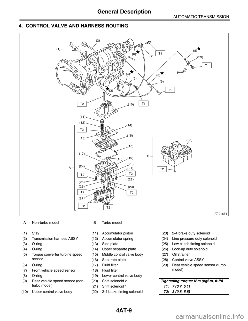
4. CONTROL VALVE AND HARNESS ROUTING
A Non-turbo model B Turbo model
(1) Stay (11) Accumulator piston (23) 2-4 brake duty solenoid
(2) Transmission harness ASSY (12) Accumulator spring (24) Line pressure duty solenoid
(3) O-ring (13) Side plate (25) Low clutch timing solenoid
(4) O-ring (14) Upper separate plate (26) Lock-up duty solenoid
(5) Torque converter turbine speed
sensor(15) Middle control valve body (27) Oil strainer
(16) Separate plate (28) Control valve ASSY
(6) O-ring (17) Fluid filter (29) Rear vehicle speed sensor (turbo
model)
(7) Front vehicle speed sensor (18) Fluid filter
(8) O-ring (19) Lower control valve body
(9) Rear vehicle speed sensor (non-
turbo model)(20) Shift solenoid 2Tightening torque: N
⋅m (kgf-m, ft-lb)
(21) Shift solenoid 1T1: 7 (0.7, 5.1)
(10) Upper control valve body (22) 2-4 brake timing solenoidT2: 8 (0.8, 5.8)
AT-01864
T1T2
T2
T2
T2
T2
T2
T2T2
T2
T1
(1)(2)
(3)(4)
(5)
(6)
(7)
(10)
(11)
(12)
(14)
(13)(15)
(16)
(17)
A(24)(19)
(18)
(20)
(21)
(22)
(23) (26) (25)
(27)
(28)
B
T1
(8)
(9)
T1
(8)
(29)
Page 2331 of 2870
4AT-19
AUTOMATIC TRANSMISSION
General Description
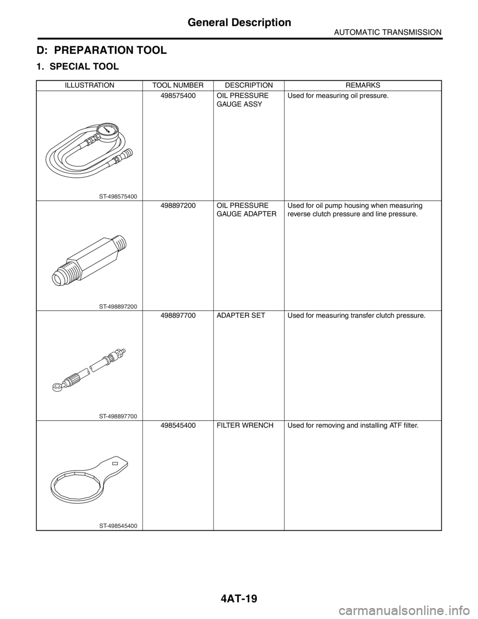
D: PREPARATION TOOL
1. SPECIAL TOOL
ILLUSTRATION TOOL NUMBER DESCRIPTION REMARKS
498575400 OIL PRESSURE
GAUGE ASSYUsed for measuring oil pressure.
498897200 OIL PRESSURE
GAUGE ADAPTERUsed for oil pump housing when measuring
reverse clutch pressure and line pressure.
498897700 ADAPTER SET Used for measuring transfer clutch pressure.
498545400 FILTER WRENCH Used for removing and installing ATF filter.
ST-498575400
ST-498897200
ST-498897700
ST-498545400
Page 2379 of 2870
4AT-66
AUTOMATIC TRANSMISSION
Control Valve Body
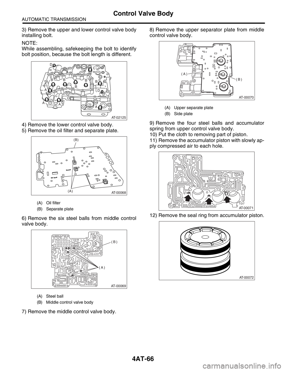
3) Remove the upper and lower control valve body
installing bolt.
NOTE:
While assembling, safekeeping the bolt to identify
bolt position, because the bolt length is different.
4) Remove the lower control valve body.
5) Remove the oil filter and separate plate.
6) Remove the six steel balls from middle control
valve body.
7) Remove the middle control valve body.8) Remove the upper separator plate from middle
control valve body.
9) Remove the four steel balls and accumulator
spring from upper control valve body.
10) Put the cloth to removing part of piston.
11) Remove the accumulator piston with slowly ap-
ply compressed air to each hole.
12) Remove the seal ring from accumulator piston.
(A) Oil filter
(B) Separate plate
(A) Steel ball
(B) Middle control valve body
AT-02125
B
B
BB D
C
B
D
AA
AA
AT-00068(A)(B)
AT-00069
(A)(B)
(A) Upper separate plate
(B) Side plate
AT-00070
(A)
(B)
AT-00071
AT-00072
Page 2380 of 2870
4AT-67
AUTOMATIC TRANSMISSION
Control Valve Body
D: ASSEMBLY
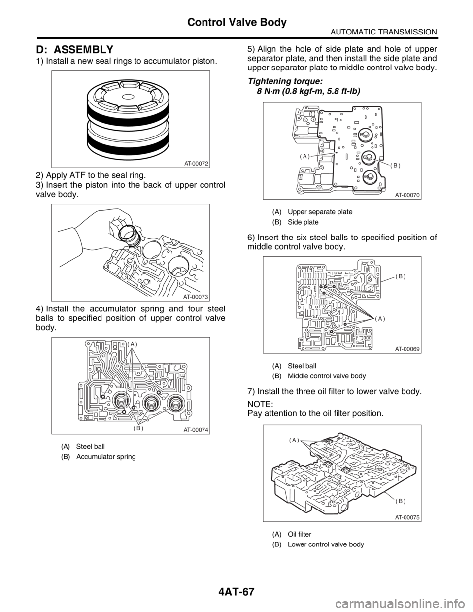
1) Install a new seal rings to accumulator piston.
2) Apply ATF to the seal ring.
3) Insert the piston into the back of upper control
valve body.
4) Install the accumulator spring and four steel
balls to specified position of upper control valve
body.5) Align the hole of side plate and hole of upper
separator plate, and then install the side plate and
upper separator plate to middle control valve body.
Tightening torque:
8 N
⋅m (0.8 kgf-m, 5.8 ft-lb)
6) Insert the six steel balls to specified position of
middle control valve body.
7) Install the three oil filter to lower valve body.
NOTE:
Pay attention to the oil filter position.
(A) Steel ball
(B) Accumulator spring
AT-00072
AT-00073
AT-00074
(A)
(B)
(A) Upper separate plate
(B) Side plate
(A) Steel ball
(B) Middle control valve body
(A) Oil filter
(B) Lower control valve body
AT-00070
(A)
(B)
AT-00069
(A)(B)
AT-00075
(A)
(B)
Page 2381 of 2870
4AT-68
AUTOMATIC TRANSMISSION
Control Valve Body
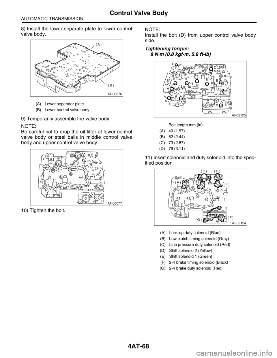
8) Install the lower separate plate to lower control
valve body.
9) Temporarily assemble the valve body.
NOTE:
Be careful not to drop the oil filter of lower control
valve body or steel balls in middle control valve
body and upper control valve body.
10) Tighten the bolt.NOTE:
Install the bolt (D) from upper control valve body
side.
Tightening torque:
8 N
⋅m (0.8 kgf-m, 5.8 ft-lb)
11) Insert solenoid and duty solenoid into the spec-
ified position.
(A) Lower separator plate
(B) Lower control valve body
AT-00076
(A)
(B)
AT-00077
Bolt length mm (in)
(A) 40 (1.57)
(B) 62 (2.44)
(C) 73 (2.87)
(D) 79 (3.11)
(A) Lock-up duty solenoid (Blue)
(B) Low clutch timing solenoid (Gray)
(C) Line pressure duty solenoid (Red)
(D) Shift solenoid 2 (Yellow)
(E) Shift solenoid 1 (Green)
(F) 2-4 brake timing solenoid (Black)
(G) 2-4 brake duty solenoid (Red)
AT-02125
B
B
BB D
C
B
D
AA
AA
AT-02124
(E)
(F)(G)
(D)(C)
(B)(A)
Page 2389 of 2870
4AT-76
AUTOMATIC TRANSMISSION
ATF Filter
21.ATF Filter
A: REMOVAL
NOTE:
The ATF filter is maintenance free.
1) Lift-up the vehicle.
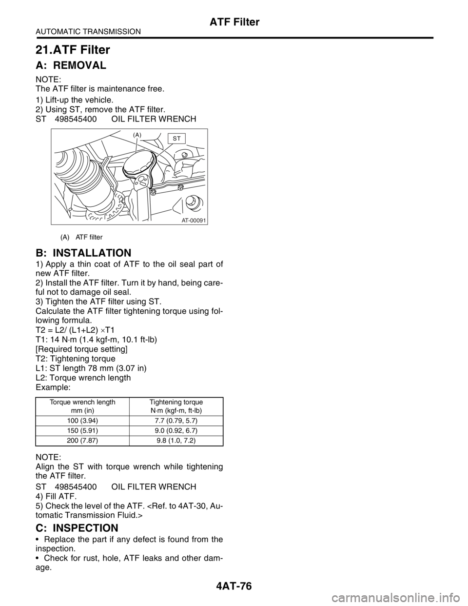
2) Using ST, remove the ATF filter.
ST 498545400 OIL FILTER WRENCH
B: INSTALLATION
1) Apply a thin coat of ATF to the oil seal part of
new ATF filter.
2) Install the ATF filter. Turn it by hand, being care-
ful not to damage oil seal.
3) Tighten the ATF filter using ST.
Calculate the ATF filter tightening torque using fol-
lowing formula.
T2 = L2/ (L1+L2) ×T1
T1: 14 N⋅m (1.4 kgf-m, 10.1 ft-lb)
[Required torque setting]
T2: Tightening torque
L1: ST length 78 mm (3.07 in)
L2: Torque wrench length
Example:
NOTE:
Align the ST with torque wrench while tightening
the ATF filter.
ST 498545400 OIL FILTER WRENCH
4) Fill ATF.
5) Check the level of the ATF.
C: INSPECTION
Replace the part if any defect is found from the
inspection.
Check for rust, hole, ATF leaks and other dam-
age.
(A) ATF filter
Torque wrench length
mm (in)Tightening torque
N⋅m (kgf-m, ft-lb)
100 (3.94) 7.7 (0.79, 5.7)
150 (5.91) 9.0 (0.92, 6.7)
200 (7.87) 9.8 (1.0, 7.2)
AT-00091
(A)ST