2004 SUBARU FORESTER oil filter
[x] Cancel search: oil filterPage 1543 of 2870

ME(H4DOTC)-83
MECHANICAL
Cylinder Block
20.Cylinder Block
A: REMOVAL
NOTE:
Before conducting this procedure, drain the engine
oil completely if applicable.
1) Remove the intake manifold.
2) Remove the V-belt.
3) Remove the crank pulley.
4) Remove the timing belt cover.
5) Remove the timing belt assembly.
bly.>
6) Remove the cam sprocket.
7) Remove the crank sprocket.
8) Remove the generator and A/C compressor with
their brackets.
9) Remove the cylinder head assembly.
sembly.>
10) Remove the clutch disc and cover. (MT model)
11) Remove the flywheel. (MT model)
12) Remove the drive plate. (AT model)
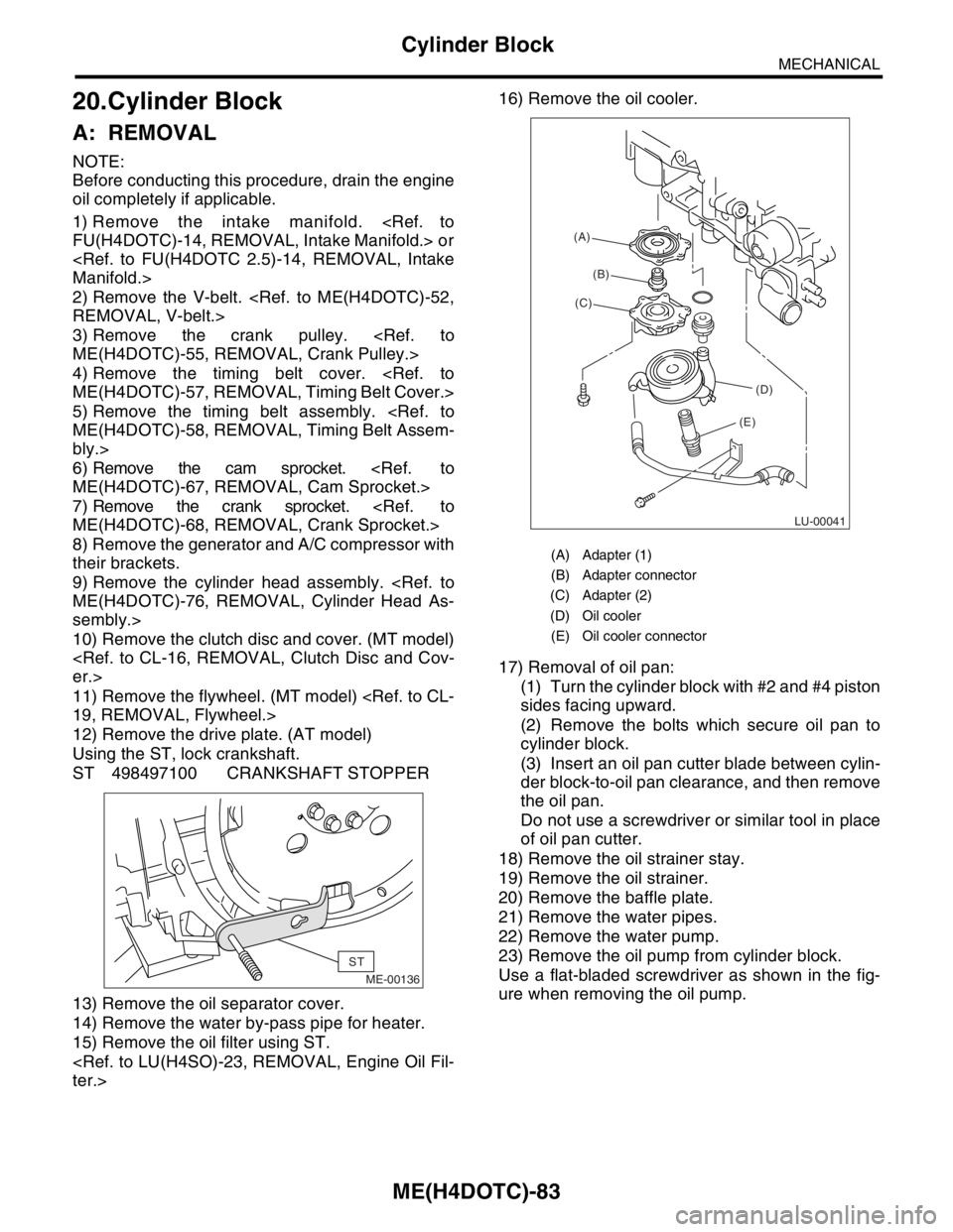
Using the ST, lock crankshaft.
ST 498497100 CRANKSHAFT STOPPER
13) Remove the oil separator cover.
14) Remove the water by-pass pipe for heater.
15) Remove the oil filter using ST.
17) Removal of oil pan:
(1) Turn the cylinder block with #2 and #4 piston
sides facing upward.
(2) Remove the bolts which secure oil pan to
cylinder block.
(3) Insert an oil pan cutter blade between cylin-
der block-to-oil pan clearance, and then remove
the oil pan.
Do not use a screwdriver or similar tool in place
of oil pan cutter.
18) Remove the oil strainer stay.
19) Remove the oil strainer.
20) Remove the baffle plate.
21) Remove the water pipes.
22) Remove the water pump.
23) Remove the oil pump from cylinder block.
Use a flat-bladed screwdriver as shown in the fig-
ure when removing the oil pump.
ME-00136
ST
(A) Adapter (1)
(B) Adapter connector
(C) Adapter (2)
(D) Oil cooler
(E) Oil cooler connector
LU-00041
(A)
(B)
(C)
(D)
(E)
Page 1555 of 2870

ME(H4DOTC)-95
MECHANICAL
Cylinder Block
33) Install the oil filter using ST.
34) Install the water by-pass pipe between oil cool-
er and water pump.
35) Install the water pipe.
NOTE:
Always use a new O-ring.
36) Install the cylinder head assembly.
Assembly.>
37) Install the oil level gauge guide and tighten the
attaching bolt (LH side).
38) Install the rocker cover.
39) Install the crank sprocket.
et.>40) Install the cam sprocket.
et.>
41) Install the timing belt assembly.
Assembly.>
42) Install the timing belt cover.
Cover.>
43) Install the crank pulley.
44) Install the generator and A/C compressor
brackets on cylinder head.
45) Install the V-belt.
46) Install the intake manifold.
fold.>
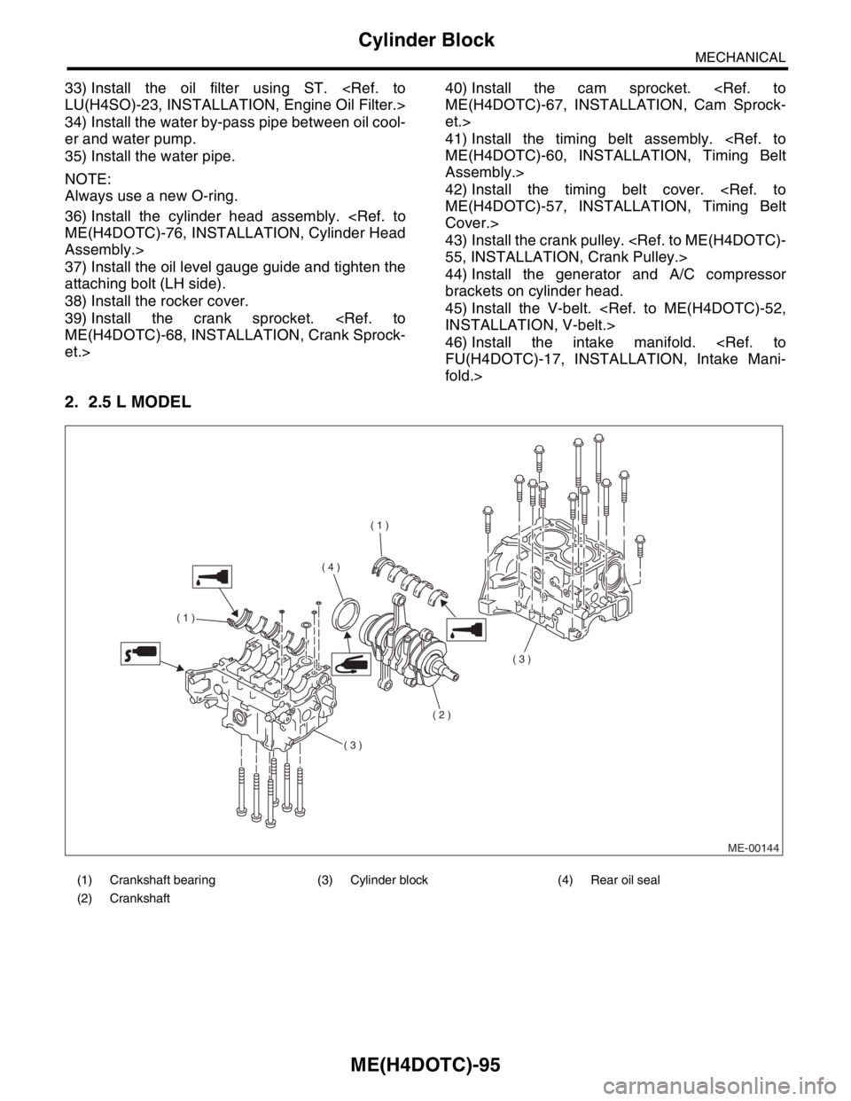
2. 2.5 L MODEL
(1) Crankshaft bearing (3) Cylinder block (4) Rear oil seal
(2) Crankshaft
ME-00144
( 1 )
( 1 )
( 2 )
( 3 )
( 3 )
( 4 )
Page 1563 of 2870

ME(H4DOTC)-103
MECHANICAL
Cylinder Block
NOTE:
Be sure to use a new gasket.
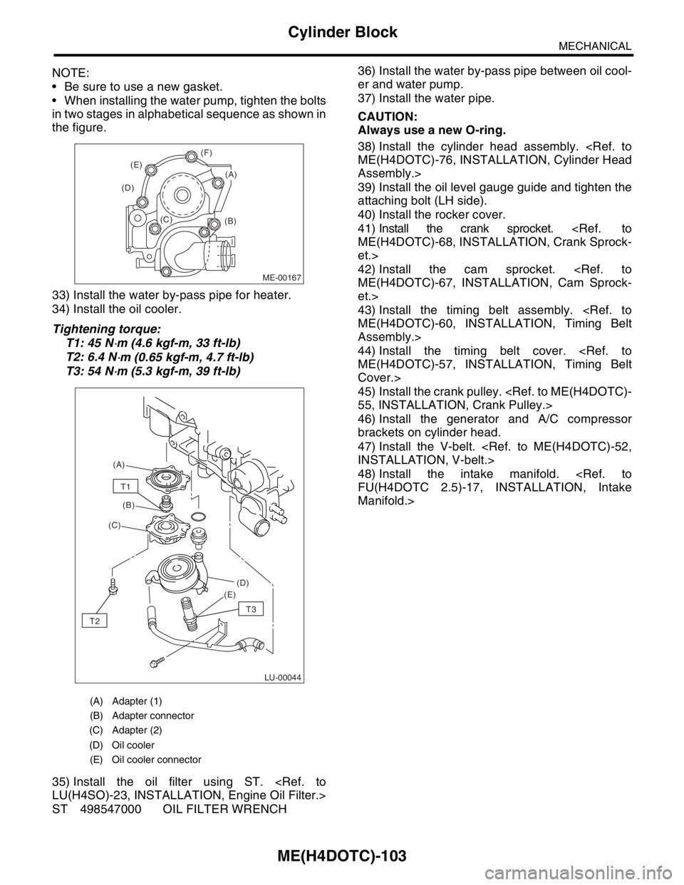
When installing the water pump, tighten the bolts
in two stages in alphabetical sequence as shown in
the figure.
33) Install the water by-pass pipe for heater.
34) Install the oil cooler.
Tightening torque:
T1: 45 N
⋅m (4.6 kgf-m, 33 ft-lb)
T2: 6.4 N
⋅m (0.65 kgf-m, 4.7 ft-lb)
T3: 54 N
⋅m (5.3 kgf-m, 39 ft-lb)
35) Install the oil filter using ST.
ST 498547000 OIL FILTER WRENCH36) Install the water by-pass pipe between oil cool-
er and water pump.
37) Install the water pipe.
CAUTION:
Always use a new O-ring.
38) Install the cylinder head assembly.
Assembly.>
39) Install the oil level gauge guide and tighten the
attaching bolt (LH side).
40) Install the rocker cover.
41) Install the crank sprocket.
et.>
42) Install the cam sprocket.
et.>
43) Install the timing belt assembly.
Assembly.>
44) Install the timing belt cover.
Cover.>
45) Install the crank pulley.
46) Install the generator and A/C compressor
brackets on cylinder head.
47) Install the V-belt.
48) Install the intake manifold.
Manifold.>
(A) Adapter (1)
(B) Adapter connector
(C) Adapter (2)
(D) Oil cooler
(E) Oil cooler connector
ME-00167
(B) (C) (D)(E)(F)
(A)
LU-00044
(A)
(B)
(C)
(D)
(E)
T1
T2
T3
Page 1581 of 2870

ME(H4DOTC)-121
MECHANICAL
Engine Trouble in General
5. Engine does not return to
idle.Engine control system
Intake system Loosened or cracked vacuum hose A
Others Stuck or damaged throttle valve A
Accelerator cable out of adjustment (2.0 L model) B
6. Dieseling (Run-on) Engine control system
Cooling system Overheating B
Others Malfunction of evaporative emission control system B
7. Afterburning in exhaust
systemEngine control system
Intake system Loosened or cracked intake duct C
Loosened or cracked PCV hose C
Loosened or cracked vacuum hose B
Defective PCV valve B
Loosened oil filler cap C
Belt Defective timing B
Compression Incorrect valve clearance B
Loosened spark plugs or defective gasket C
Loosened cylinder head bolts or defective gasket C
Improper valve seating B
Defective valve stem C
Worn or broken valve spring C
Worn or stuck piston rings, cylinder and piston C
Incorrect valve timing A
Lubrication system Incorrect oil pressure C
Cooling system Over cooling C
Others Malfunction of evaporative emission control system C
8. Knocking Engine control system
Intake system Loosened oil filler cap B
Belt Defective timing B
Compression Incorrect valve clearance C
Incorrect valve timing B
Cooling system Overheating A
9. Excessive engine oil con-
sumptionIntake system Loosened or cracked PCV hose A
Defective PCV valve B
Loosened oil filler cap C
Compression Defective valve stem A
Worn or stuck piston rings, cylinder and piston A
Lubrication system Loosened oil pump attaching bolts and defective gas-
ketB
Defective oil filter o-ring B
Defective crankshaft oil seal B
Defective rocker cover gasket B
Loosened oil drain plug or defective gasket B
Loosened oil pan fitting bolts or defective oil pan B TROUBLE PROBLEM PARTS, ETC. POSSIBLE CAUSE RANK
Page 1713 of 2870

EN(H4DOTC)-80
ENGINE (DIAGNOSTIC)
Diagnostic Procedure with Diagnostic Trouble Code (DTC)
19.Diagnostic Procedure with Diagnostic Trouble Code (DTC)
A: DTC P0011 “A” CAMSHAFT POSITION - TIMING OVER - ADVANCED OR
SYSTEM PERFORMANCE (BANK 1)
DTC DETECTING CONDITION:
Detect as soon as the malfunction occurs.
TROUBLE SYMPTOM:
Engine stalls.
Erroneous idling
CAUTION:
After repair or replacement of faulty parts, conduct Clear Memory Mode
Step Check Yes No
1 CHECK DTC ON DISPLAY.Is any other DTC displayed? Inspect the rele-
vant DTC using
“List of Diagnostic
Trouble Code
(DTC)”.
List of Diagnostic
Trouble Code
(DTC).>Go to step 2.
2 CHECK CURRENT DATA.
1) Start the engine and idle it.
2) Check the AVCS system operating angle
and oil flow control solenoid valve duty output
using Subaru Select Monitor or OBD-II general
scan tool.
N
OTE:
Subaru Select Monitor
For detailed operation procedure, refer to
“READ CURRENT DATA SHOWN ON DIS-
PLAY FOR ENGINE”.
OBD-II general scan tool
For detailed operation procedures, refer to the
OBD-II General Scan Tool Operation Manual.Is the AVCS system operating
angle approx. 0 degree and oil
flow control solenoid valve duty
output approx. 10%?A temporary poor
malfunction. Per-
for m the following
to clean oil routing.
Replace the
engine oil, and
then idle the
engine for 5 min-
utes and replace
the oil filter and
engine oil.Check the follow-
ing and repair or
replace it if neces-
sary.
Oil pipe (clog-
ging)
Oil flow con-
trol solenoid
valve (clogging
or dirt of oil
routing, spring
setting, clog-
ging of valve)
Intake cam-
shaft (dirt, dam-
age of
camshaft)
Timing belt
(alignment of
timing mark)
Page 1714 of 2870

EN(H4DOTC)-81
ENGINE (DIAGNOSTIC)
Diagnostic Procedure with Diagnostic Trouble Code (DTC)
B: DTC P0021 “A” CAMSHAFT POSITION - TIMING OVER - ADVANCED OR
SYSTEM PERFORMANCE (BANK 2)
DTC DETECTING CONDITION:
Detect as soon as the malfunction occurs.
TROUBLE SYMPTOM:
Engine stalls.
Erroneous idling
CAUTION:
After repair or replacement of faulty parts, conduct Clear Memory Mode
Step Check Yes No
1 CHECK DTC ON DISPLAY.Is any other DTC displayed? Inspect the rele-
vant DTC using
“List of Diagnostic
Trouble Code
(DTC)”.
List of Diagnostic
Trouble Code
(DTC).>Go to step 2.
2 CHECK CURRENT DATA.
1) Start the engine and idle it.
2) Check the AVCS system operating angle
and oil flow control solenoid valve duty output
using Subaru Select Monitor or OBD-II general
scan tool.
NOTE:
Subaru Select Monitor
For detailed operation procedure, refer to
“READ CURRENT DATA SHOWN ON DIS-
PLAY FOR ENGINE”.
OBD-II general scan tool
For detailed operation procedures, refer to the
OBD-II General Scan Tool Operation Manual.Is the AVCS system operating
angle approx. 0 degree and oil
flow control solenoid valve duty
output approx. 10%?A temporary poor
malfunction. Per-
for m the following
to clean oil routing.
Replace the
engine oil, and
then idle the
engine for 5 min-
utes and replace
the oil filter and
engine oil.Check the follow-
ing and repair or
replace it if neces-
sary.
Engine oil
(amount, dirt)
Oil pipe (clog-
ging)
Oil flow con-
trol solenoid
valve (clogging
or dirt of oil
routing, spring
setting, clog-
ging of valve)
Intake cam-
shaft (dirt, dam-
age of
camshaft)
Timing belt
(alignment of
timing mark)
Page 1929 of 2870

EN(H4DOTC)-296
ENGINE (DIAGNOSTIC)
General Diagnostic Table
*1: Check ignition coil & ignitor ASSY and spark plug.
*2: Indicate the symptom occurring only in cold temperatures.
*3: Ensure the secure installation.
*4: Check fuel injector, fuel pressure regulator and fuel filter.
*5: Inspect air leak in air intake system.
*6: Adjust accelerator cable. 6. Surging1) Manifold absolute pressure sensor
2) Mass air flow and intake air temperature sensor
3) Engine coolant temperature sensor (*2)
4) Crankshaft position sensor (*3)
5) Camshaft position sensor (*3)
6) Fuel injection parts (*4)
7) Throttle position sensor
8) Fuel pump and fuel pump relay
7. Spark knock1) Manifold absolute pressure sensor
2) Mass air flow and intake air temperature sensor
3) Engine coolant temperature sensor
4) Knock sensor
5) Fuel injection parts (*4)
6) Fuel pump and fuel pump relay
8. After burning in exhaust system1) Manifold absolute pressure sensor
2) Mass air flow and intake air temperature sensor
3) Engine coolant temperature sensor (*2)
4) Fuel injection parts (*4)
5) Fuel pump and fuel pump relay Symptom Problem parts
Page 2283 of 2870

EN(H4DOTC 2.5)-259
ENGINE (DIAGNOSTIC)
General Diagnostic Table
*1: Check ignition coil & ignitor ASSY and spark plug.
*2: Indicate the symptom occurring only in cold temperatures.
*3: Ensure the secure installation.
*4: Check fuel injector, fuel pressure regulator and fuel filter.
*5: Inspect air leak in air intake system. 7. Spark knock1) Manifold absolute pressure sensor
2) Mass air flow and intake air temperature sensor
3) Engine coolant temperature sensor
4) Knock sensor
5) Fuel injection parts (*4)
6) Fuel pump and fuel pump relay
8. After burning in exhaust system1) Manifold absolute pressure sensor
2) Mass air flow and intake air temperature sensor
3) Engine coolant temperature sensor (*2)
4) Fuel injection parts (*4)
5) Fuel pump and fuel pump relay Symptom Problem parts