Page 880 of 2870

ME(H4SO)-11
MECHANICAL
General Description
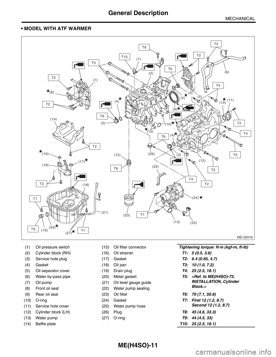
MODEL WITH ATF WARMER
(1) Oil pressure switch (15) Oil filter connectorTightening torque: N⋅m (kgf-m, ft-lb)
(2) Cylinder block (RH) (16) Oil strainerT1: 5 (0.5, 3.6)
(3) Service hole plug (17) GasketT2: 6.4 (0.65, 4.7)
(4) Gasket (18) Oil panT3: 10 (1.0, 7.2)
(5) Oil separator cover (19) Drain plugT4: 25 (2.5, 18.1)
(6) Water by-pass pipe (20) Metal gasketT5:
INSTALLATION, Cylinder
Block.> (7) Oil pump (21) Oil level gauge guide
(8) Front oil seal (22) Water pump sealing
(9) Rear oil seal (23) Oil filterT6: 70 (7.1, 50.6)
(10) O-ring (24) GasketT7: First 12 (1.2, 8.7)
Second 12 (1.2, 8.7)
(11) Service hole cover (25) Water pump hose
(12) Cylinder block (LH) (26) PlugT8: 45 (4.6, 33.3)
(13) Water pump (27) O-ringT9: 44 (4.5, 33)
(14) Baffle plateT10: 25 (2.5, 18.1)
ME-02016
(14)
T6
T2
T2
T4
T8
T5
T2
T6
T6
T10
T1
T2
T8
T1
T3
T9
T2
T2
(9) (8)(7)
(10)
(10)
(10)
(26)
(22)(11)
(12)
(19)(18)
(20)(17)
(16)
(24) (10)
(25)(5)
(4)
(4)
(4)(3)
(3)
(3) (2) (1)
(21)(15)
(23)
T5
T2
T5
T4
(27)
T7
(13)
(6)
T4
Page 886 of 2870
ME(H4SO)-17
MECHANICAL
General Description
498457100 ENGINE STAND
ADAPTER LHUsed with ENGINE STAND (499817000).
498497100 CRANKSHAFT
STOPPERUsed for stopping rotation of flywheel when loos-
ening and tightening crank pulley bolt, etc.
498547000 OIL FILTER
WRENCHUsed for removing and installing oil filter.
(Outer diameter : 80 mm (3.15 in))
18332AA000 OIL FILTER
WRENCHUsed for removing and installing oil filter.
(Outer diameter : 68 mm (2.68 in)) ILLUSTRATION TOOL NUMBER DESCRIPTION REMARKS
ST-498457100
ST-498497100
ST-498547000
ST18332AA000
Page 887 of 2870
ME(H4SO)-18
MECHANICAL
General Description
18332AA010 OIL FILTER
WRENCHUsed for removing and installing oil filter.
(Outer diameter : 65 mm (2.56 in))
398744300
(2.0 L model)PISTON GUIDE Used for installing piston in cylinder.
498747300
(2.5 L model)PISTON GUIDE Used for installing piston in cylinder.
498857100 VALVE OIL SEAL
GUIDEUsed for press-fitting of intake and exhaust valve
guide oil seals. ILLUSTRATION TOOL NUMBER DESCRIPTION REMARKS
ST18332AA010
ST-398744300
ST-498747300
ST-498857100
Page 898 of 2870

ME(H4SO)-29
MECHANICAL
Engine Oil Pressure
6. Engine Oil Pressure
A: INSPECTION
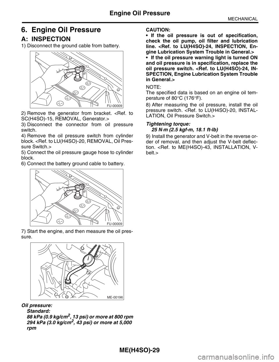
1) Disconnect the ground cable from battery.
2) Remove the generator from bracket.
SC(H4SO)-15, REMOVAL, Generator.>
3) Disconnect the connector from oil pressure
switch.
4) Remove the oil pressure switch from cylinder
block.
sure Switch.>
5) Connect the oil pressure gauge hose to cylinder
block.
6) Connect the battery ground cable to battery.
7) Start the engine, and then measure the oil pres-
sure.
Oil pressure:
Standard:
88 kPa (0.9 kg/cm
2, 13 psi) or more at 800 rpm
294 kPa (3.0 kg/cm2, 43 psi) or more at 5,000
rpmCAUTION:
If the oil pressure is out of specification,
check the oil pump, oil filter and lubrication
line.
gine Lubrication System Trouble in General.>
If the oil pressure warning light is turned ON
and oil pressure is in specification, replace the
oil pressure switch.
SPECTION, Engine Lubrication System Trouble
in General.>
NOTE:
The specified data is based on an engine oil tem-
perature of 80°C (176°F).
8) After measuring the oil pressure, install the oil
pressure switch.
LATION, Oil Pressure Switch.>
Tightening torque:
25 N
⋅m (2.5 kgf-m, 18.1 ft-lb)
9) Install the generator and V-belt in the reverse or-
der of removal, and then adjust the V-belt deflec-
tion.
belt.>
FU-00009
FU-00009
ME-00196
Page 941 of 2870

ME(H4SO)-70
MECHANICAL
Cylinder Block
NOTE:
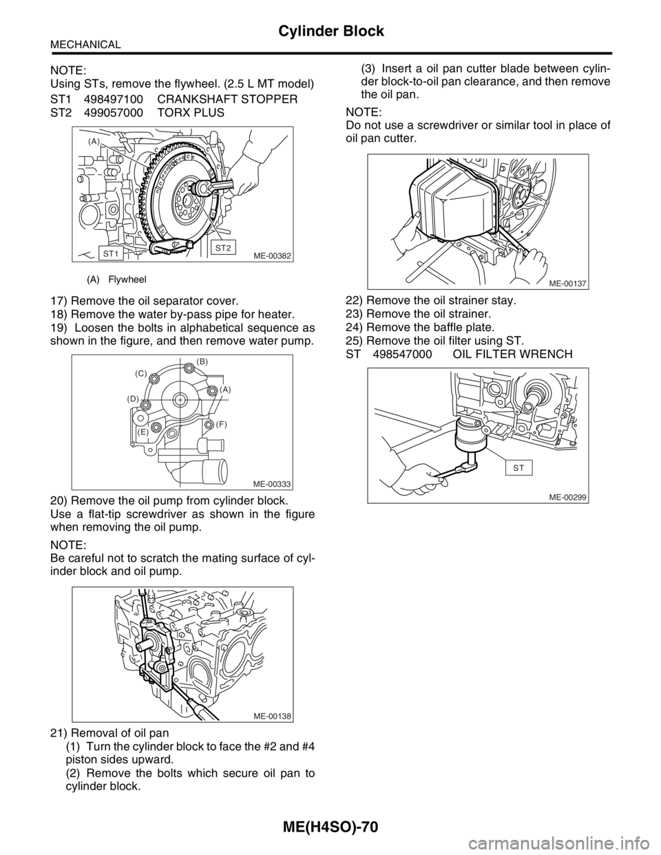
Using STs, remove the flywheel. (2.5 L MT model)
ST1 498497100 CRANKSHAFT STOPPER
ST2 499057000 TORX PLUS
17) Remove the oil separator cover.
18) Remove the water by-pass pipe for heater.
19) Loosen the bolts in alphabetical sequence as
shown in the figure, and then remove water pump.
20) Remove the oil pump from cylinder block.
Use a flat-tip screwdriver as shown in the figure
when removing the oil pump.
NOTE:
Be careful not to scratch the mating surface of cyl-
inder block and oil pump.
21) Removal of oil pan
(1) Turn the cylinder block to face the #2 and #4
piston sides upward.
(2) Remove the bolts which secure oil pan to
cylinder block.(3) Insert a oil pan cutter blade between cylin-
der block-to-oil pan clearance, and then remove
the oil pan.
NOTE:
Do not use a screwdriver or similar tool in place of
oil pan cutter.
22) Remove the oil strainer stay.
23) Remove the oil strainer.
24) Remove the baffle plate.
25) Remove the oil filter using ST.
ST 498547000 OIL FILTER WRENCH
(A) Flywheel
(A)
ME-00382
ST1ST2
ME-00333
(B)
(F) (D)(C)
(A)
(E)
ME-00138
ME-00137
ME-00299
ST
Page 952 of 2870

ME(H4SO)-81
MECHANICAL
Cylinder Block
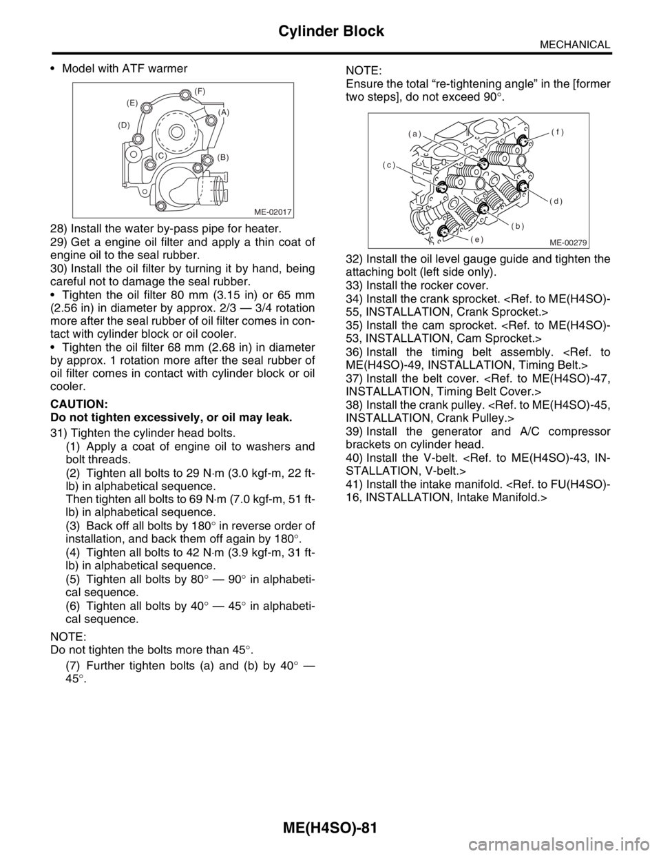
Model with ATF warmer
28) Install the water by-pass pipe for heater.
29) Get a engine oil filter and apply a thin coat of
engine oil to the seal rubber.
30) Install the oil filter by turning it by hand, being
careful not to damage the seal rubber.
Tighten the oil filter 80 mm (3.15 in) or 65 mm
(2.56 in) in diameter by approx. 2/3 — 3/4 rotation
more after the seal rubber of oil filter comes in con-
tact with cylinder block or oil cooler.
Tighten the oil filter 68 mm (2.68 in) in diameter
by approx. 1 rotation more after the seal rubber of
oil filter comes in contact with cylinder block or oil
cooler.
CAUTION:
Do not tighten excessively, or oil may leak.
31) Tighten the cylinder head bolts.
(1) Apply a coat of engine oil to washers and
bolt threads.
(2) Tighten all bolts to 29 N⋅m (3.0 kgf-m, 22 ft-
lb) in alphabetical sequence.
Then tighten all bolts to 69 N⋅m (7.0 kgf-m, 51 ft-
lb) in alphabetical sequence.
(3) Back off all bolts by 180° in reverse order of
installation, and back them off again by 180°.
(4) Tighten all bolts to 42 N⋅m (3.9 kgf-m, 31 ft-
lb) in alphabetical sequence.
(5) Tighten all bolts by 80° — 90° in alphabeti-
cal sequence.
(6) Tighten all bolts by 40° — 45° in alphabeti-
cal sequence.
NOTE:
Do not tighten the bolts more than 45°.
(7) Further tighten bolts (a) and (b) by 40° —
45°.NOTE:
Ensure the total “re-tightening angle” in the [former
two steps], do not exceed 90°.
32) Install the oil level gauge guide and tighten the
attaching bolt (left side only).
33) Install the rocker cover.
34) Install the crank sprocket.
55, INSTALLATION, Crank Sprocket.>
35) Install the cam sprocket.
53, INSTALLATION, Cam Sprocket.>
36) Install the timing belt assembly.
ME(H4SO)-49, INSTALLATION, Timing Belt.>
37) Install the belt cover.
INSTALLATION, Timing Belt Cover.>
38) Install the crank pulley.
INSTALLATION, Crank Pulley.>
39) Install the generator and A/C compressor
brackets on cylinder head.
40) Install the V-belt.
STALLATION, V-belt.>
41) Install the intake manifold.
16, INSTALLATION, Intake Manifold.>
ME-02017
(B) (C) (D)(E)(F)
(A)
ME-00279
(c)
(b)(f)
(d) (a)
(e)
Page 965 of 2870

ME(H4SO)-94
MECHANICAL
Engine Trouble in General
5. Engine does not return to
idle.Engine control system A
Intake system Loosened or cracked vacuum hose A
Others Stuck or damaged throttle valve A
Accelerator cable out of adjustment B
6. Dieseling (Run-on) Engine control system A
Cooling system Overheating B
Others Malfunction of evaporative emission control system B
7. After burning in exhaust
systemEngine control system A
Intake system Loosened or cracked intake duct C
Loosened or cracked PCV hose C
Loosened or cracked vacuum hose B
Defective PCV valve B
Loosened oil filler cap C
Belt Defective timing B
Compression Incorrect valve clearance B
Loosened spark plugs or defective gasket C
Loosened cylinder head bolts or defective gasket C
Improper valve seating B
Defective valve stem C
Worn or broken valve spring C
Worn or stuck piston rings, cylinder and piston C
Incorrect valve timing A
Lubrication system Incorrect oil pressure C
Cooling system Over cooling C
Others Malfunction of evaporative emission control system C
8. Knocking Engine control system A
Intake system Loosened oil filler cap B
Belt Defective timing B
Compression Incorrect valve clearance C
Incorrect valve timing B
Cooling system Overheating A
9. Excessive engine oil con-
sumptionIntake system Loosened or cracked PCV hose A
Defective PCV valve B
Loosened oil filler cap C
Compression Defective valve stem A
Worn or stuck piston rings, cylinder and piston A
Lubrication system Loosened oil pump attaching bolts and defective gas-
ketB
Defective oil filter seal B
Defective crankshaft oil seal B
Defective rocker cover gasket B
Loosened oil drain plug or defective gasket B
Loosened oil pan fitting bolts or defective oil pan B TROUBLE PROBLEM PARTS, ETC. POSSIBLE CAUSE RANK
Page 1029 of 2870

LUBRICATION
LU(H4SO)
Page
1. General Description ....................................................................................2
2. Oil Pressure System ...................................................................................8
3. Engine Oil..................................................................................................10
4. Oil Pump ...................................................................................................12
5. Oil Pan and Strainer ..................................................................................16
6. Oil Pressure Switch ...................................................................................20
7. Engine Oil Cooler ......................................................................................21
8. Engine Oil Filter.........................................................................................23
9. Engine Lubrication System Trouble in General.........................................24