Page 1030 of 2870

LU(H4SO)-2
LUBRICATION
General Description
1. General Description
A: SPECIFICATION
Lubrication methodForced lubrication
Oil pumpPump type Trochoid type
Number of teethInner rotor 9
Outer rotor 10
Outer rotor diameter×thicknessNon-turbo model 78×7 mm (3.07×0.28 in)
Turbo model 78×10 mm (3.07×0.39 in)
Tip clearance between inner and outer rotorStandard 0.04 — 0.14 mm (0.0016 — 0.0055 in)
Limit 0.18 mm (0.0071 in)
Side clearance between inner rotor and pump
caseStandard 0.02 — 0.07 mm (0.0008 — 0.0028 in)
Limit 0.12 mm (0.0047 in)
Case clearance between outer rotor and pump
caseStandard 0.10 — 0.175 mm (0.0039 — 0.0069 in)
Limit 0.20 mm (0.0079 in)
Capacity at
80°C (176°F)Non-turbo
model
600 rpmDischarge
pressure98 kPa (1.0 kg/cm
2, 14 psi)
Discharge
quantity3.22 (3.4 US qt, 2.8 Imp qt)/min.
5,000 rpmDischarge
pressure294 kPa (3.0 kg/cm
2, 43 psi)
Discharge
quantity32.62 (34.4 US qt, 28.7 Imp qt)/min.
Turbo model
600 rpmDischarge
pressure98 kPa (1.0 kg/cm
2, 14 psi)
Discharge
quantity4.62 (4.9 US qt, 4.0 Imp qt)/min.
5,000 rpmDischarge
pressure294 kPa (3.0 kg/cm
2, 43 psi)
Discharge
quantity47.02 (49.7 US qt, 41.4 Imp qt)/min.
Relief valve operation pressureNon-turbo model
490 kPa (5.0 kg/cm
2, 71 psi)
Turbo model
588 kPa (6.0 kg/cm
2, 85 psi)
Oil filterTy p eFull-flow filter type
Filtration areaNon-turbo
760 cm
2 (118 sq in)
Tu r b o
800 cm
2 (124 sq in)
By-pass valve opening pressureNon-turbo
157 kPa (1.60 kg/cm
2, 22.8 psi)
Tu r b o
160 kPa (1.63 kg/cm
2, 23.2 psi)
Outer diameter×widthNon-turbo 80×70 mm (3.15×2.76 in)
Tu r b o 6 8×65 mm (2.68×2.56 in)
Oil filter to engine thread size M 20×1.5
Oil pressure
switchType Immersed contact point type
Working voltage — wattage 12 V — 3.4 W or less
Warning light activation pressure
14.7 kPa (0.15 kg/cm
2, 2.1 psi)
Proof pressure
More than 981 kPa (10 kg/cm
2, 142 psi)
Oil capacity (at replacement) 4.02 (4.2 US qt, 3.5 Imp qt)
Page 1031 of 2870
LU(H4SO)-3
LUBRICATION
General Description
B: COMPONENT
1. NON-TURBO MODEL
(1) Plug (13) Oil pressure switch (25) Drain plug
(2) Gasket (14) Oil filler duct (26) Metal gasket
(3) Relief valve spring (15) O-ring (27) Gasket
(4) Relief valve (16) Oil filler cap
(5) Oil seal (17) O-ringTightening torque: N
⋅m (kgf-m, ft-lb)
(6) Oil pump case (18) Baffle plateT1: 5 (0.5, 3.6)
(7) Inner rotor (19) O-ringT2: 6.4 (0.65, 4.7)
(8) Outer rotor (20) Oil strainerT3: 10 (1.0, 7.2)
(9) Oil pump cover (21) Oil level gauge guideT4: 44 (4.5, 32.5)
(10) Oil filter (22) O-ringT5: 25 (2.5, 18.1)
(11) O-ring (23) Oil pan
(12) Oil pump ASSY (24) Oil level gauge
LU-02008
(12)
(11)
T5
T2
T1
T2
T2
T1
T1
T1
T3
T4
T2
(13)
(9)
(8)
(7)
(6)
(20) (19)
(27) (18)(17) (15)
(14) (16)
(24)
(23) (10)
(25)(26)
(5)
(4)
(3)(2)
(1)
(22)
(21)
T4
Page 1033 of 2870

LU(H4SO)-5
LUBRICATION
General Description
C: CAUTION
Wear working clothing, including a cap, protec-
tive goggles, and protective shoes during opera-
tion.
Remove contamination including dirt and corro-
sion before removal, installation or disassembly.
Keep the disassembled parts in order and pro-
tect them from dust or dirt.
Before removal, installation or disassembly, be
sure to clarify the failure. Avoid unnecessary re-
moval, installation, disassembly, and replacement.
Be careful not to burn yourself, because each
part in the vehicle is hot after running.
Be sure to tighten fasteners including bolts and
nuts to the specified torque.
Place shop jacks or rigid racks at the specified
points.
Before disconnecting electrical connectors of
sensors or units, be sure to disconnect the ground
cable from battery.
(1) Plug (16) Oil pressure switch (33) O-ring
(2) Gasket (17) Oil filler cap (34) Oil filter connector (model without
oil cooler)
(3) Relief valve spring (18) O-ring
(4) Relief valve (19) Oil filler duct (35) Plug (model without oil cooler)
(5) Oil seal (20) O-ring (36) O-ring
(6) Oil pump case (21) Rocker cover
(7) Inner rotor (22) Oil strainerTightening torque: N
⋅m (kgf-m, ft-lb)
(8) Outer rotor (23) GasketT1: 5 (0.5, 3.6)
(9) Oil pump cover (24) Oil level gauge guideT2: 6.4 (0.65, 4.7)
(10) Oil filter (25) Oil panT3: 10 (1.0, 7.0)
(11) Oil cooler connector (model with
oil cooler)(26) Oil level gaugeT4: 44 (4.5, 32.5)
(27) Metal gasketT5: 69 (7.0, 50.9)
(12) Water by-pass pipe (model with oil
cooler)(28) Drain plugT6: 6.4 (0.65, 4.7)
(29) O-ringT7: 25 (2.5, 18.1)
(13) Oil cooler (model with oil cooler) (30) Adapter (1)T8: 44 (4.5, 32.5)
(14) O-ring (31) Adapter (2)T9: 54 (5.5, 40)
(15) Oil pump ASSY (32) Baffle plate
Page 1034 of 2870
LU(H4SO)-6
LUBRICATION
General Description
D: PREPARATION TOOL
1. SPECIAL TOOL
ILLUSTRATION TOOL NUMBER DESCRIPTION REMARKS
499977400
(2.0 L model)CRANK PULLEY
WRENCHUsed for stopping rotation of crank pulley when
loosening and tightening crankshaft pulley bolt.
499977100
(2.5 L model)CRANK PULLEY
WRENCHUsed for stopping rotation of crank pulley when
loosening and tightening crankshaft pulley bolt.
498547000 OIL FILTER
WRENCHUsed for removing and installing oil filter.
(Outer diameter: 80 mm (3.15 in))
18332AA000 OIL FILTER
WRENCHUsed for removing and installing oil filter.
(Outer diameter: 68 mm (2.68 in))
ST-499977400
ST-499977100
ST-498547000
ST18332AA000
Page 1035 of 2870
LU(H4SO)-7
LUBRICATION
General Description
18332AA010 OIL FILTER
WRENCHUsed for removing and installing oil filter.
(Outer diameter: 65 mm (2.56 in))
499587100 OIL SEAL
INSTALLERUsed for installing oil pump oil seal. ILLUSTRATION TOOL NUMBER DESCRIPTION REMARKS
ST18332AA010
ST-499587100
Page 1038 of 2870

LU(H4SO)-10
LUBRICATION
Engine Oil
3. Engine Oil
A: INSPECTION
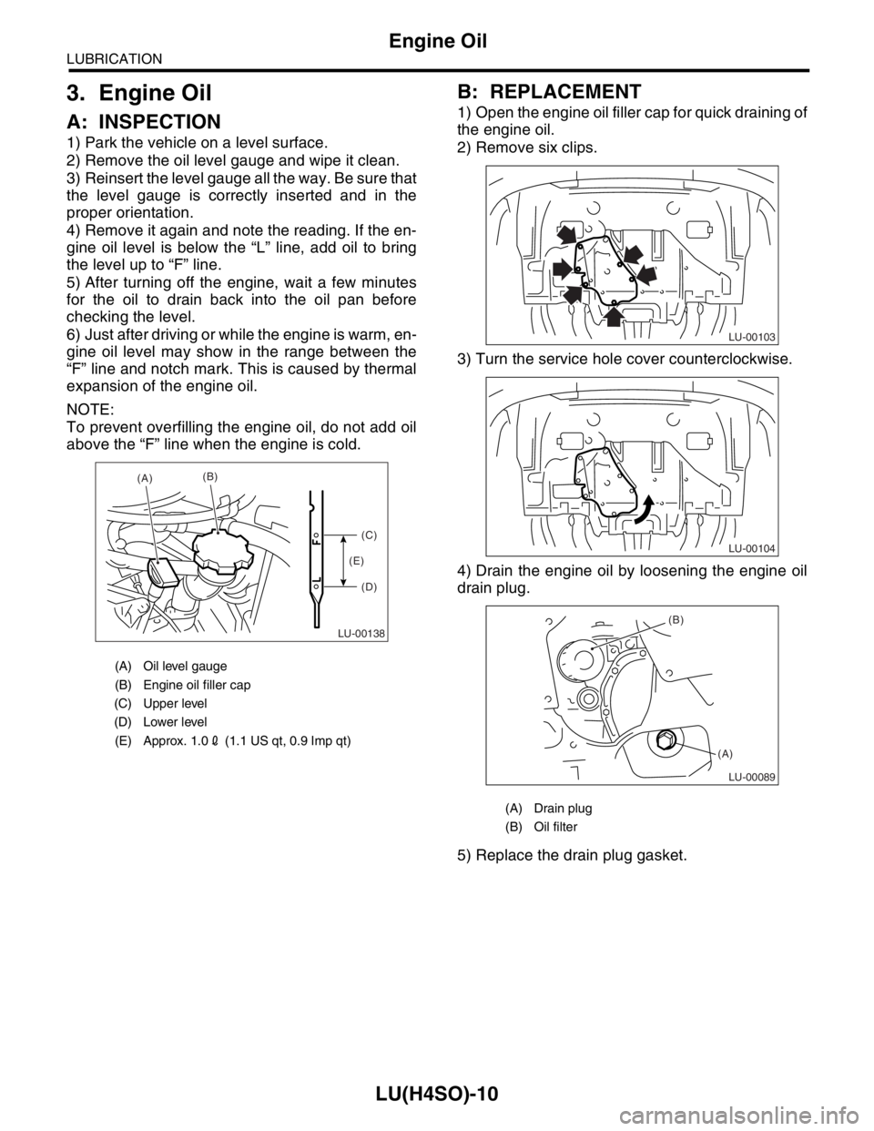
1) Park the vehicle on a level surface.
2) Remove the oil level gauge and wipe it clean.
3) Reinsert the level gauge all the way. Be sure that
the level gauge is correctly inserted and in the
proper orientation.
4) Remove it again and note the reading. If the en-
gine oil level is below the “L” line, add oil to bring
the level up to “F” line.
5) After turning off the engine, wait a few minutes
for the oil to drain back into the oil pan before
checking the level.
6) Just after driving or while the engine is warm, en-
gine oil level may show in the range between the
“F” line and notch mark. This is caused by thermal
expansion of the engine oil.
NOTE:
To prevent overfilling the engine oil, do not add oil
above the “F” line when the engine is cold.
B: REPLACEMENT
1) Open the engine oil filler cap for quick draining of
the engine oil.
2) Remove six clips.
3) Turn the service hole cover counterclockwise.
4) Drain the engine oil by loosening the engine oil
drain plug.
5) Replace the drain plug gasket.
(A) Oil level gauge
(B) Engine oil filler cap
(C) Upper level
(D) Lower level
(E) Approx. 1.02 (1.1 US qt, 0.9 Imp qt)
LU-00138
(A)(B)
(C)
(D) (E)
(A) Drain plug
(B) Oil filter
LU-00103
LU-00104
LU-00089
(B)
(A)
Page 1039 of 2870

LU(H4SO)-11
LUBRICATION
Engine Oil
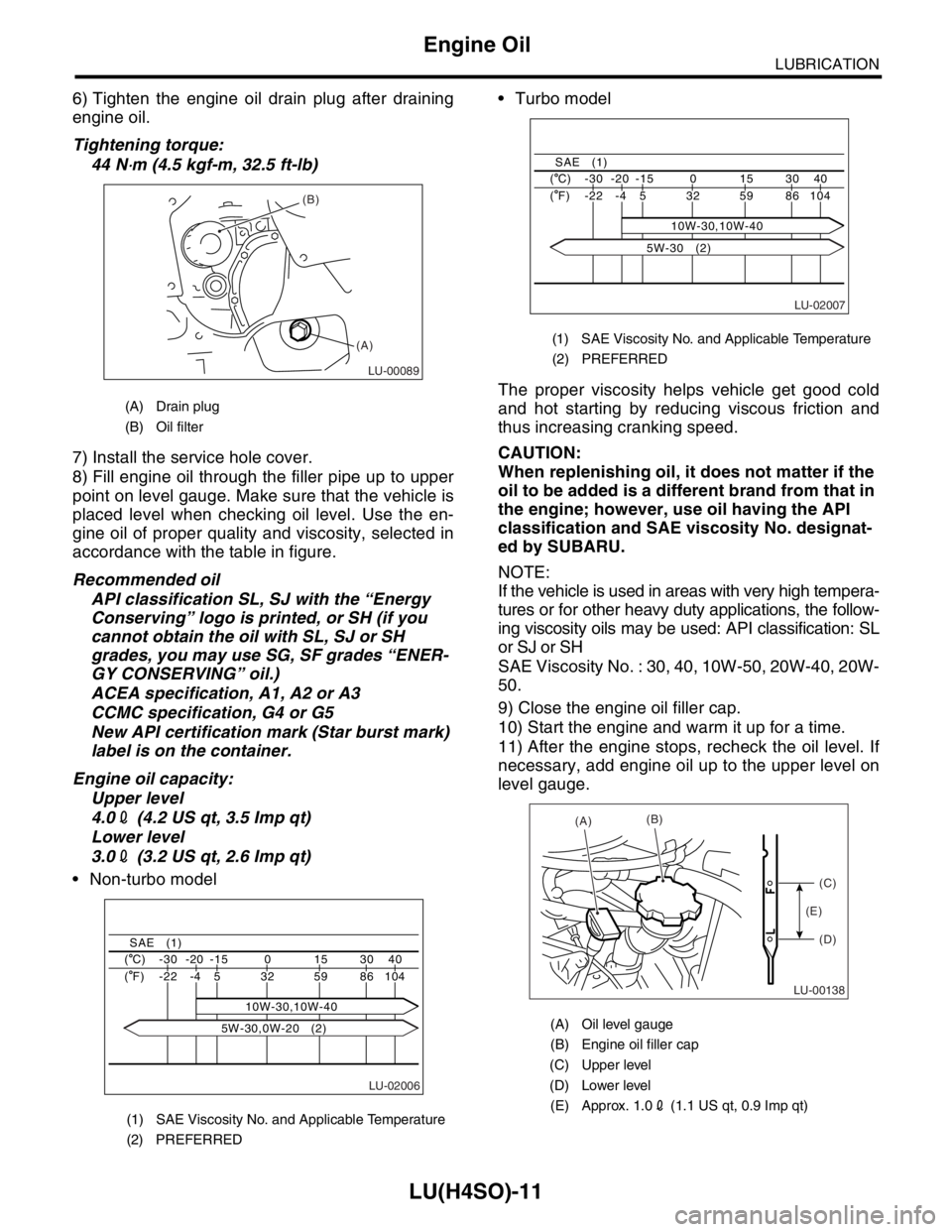
6) Tighten the engine oil drain plug after draining
engine oil.
Tightening torque:
44 N
⋅m (4.5 kgf-m, 32.5 ft-lb)
7) Install the service hole cover.
8) Fill engine oil through the filler pipe up to upper
point on level gauge. Make sure that the vehicle is
placed level when checking oil level. Use the en-
gine oil of proper quality and viscosity, selected in
accordance with the table in figure.
Recommended oil
API classification SL, SJ with the “Energy
Conserving” logo is printed, or SH (if you
cannot obtain the oil with SL, SJ or SH
grades, you may use SG, SF grades “ENER-
GY CONSERVING” oil.)
ACEA specification, A1, A2 or A3
CCMC specification, G4 or G5
New API certification mark (Star burst mark)
label is on the container.
Engine oil capacity:
Upper level
4.02 (4.2 US qt, 3.5 Imp qt)
Lower level
3.02 (3.2 US qt, 2.6 Imp qt)
Non-turbo model Turbo model
The proper viscosity helps vehicle get good cold
and hot starting by reducing viscous friction and
thus increasing cranking speed.
CAUTION:
When replenishing oil, it does not matter if the
oil to be added is a different brand from that in
the engine; however, use oil having the API
classification and SAE viscosity No. designat-
ed by SUBARU.
NOTE:
If the vehicle is used in areas with very high tempera-
tures or for other heavy duty applications, the follow-
ing viscosity oils may be used: API classification: SL
or SJ or SH
SAE Viscosity No. : 30, 40, 10W-50, 20W-40, 20W-
50.
9) Close the engine oil filler cap.
10) Start the engine and warm it up for a time.
11) After the engine stops, recheck the oil level. If
necessary, add engine oil up to the upper level on
level gauge.
(A) Drain plug
(B) Oil filter
(1) SAE Viscosity No. and Applicable Temperature
(2) PREFERRED
LU-00089
(B)
(A)
LU-02006
40 30 15 0 -15 -20 -30 ( C)
104 86 59 32
10W-30,10W-40 5 -4 -22 ( F)
SAE (1)
5W-30,0W-20 (2)
(1) SAE Viscosity No. and Applicable Temperature
(2) PREFERRED
(A) Oil level gauge
(B) Engine oil filler cap
(C) Upper level
(D) Lower level
(E) Approx. 1.02 (1.1 US qt, 0.9 Imp qt)
LU-02007
40 30 15 0 -15 -20 -30 ( C)
104 86 59 32 5 -4 -22 ( F)
SAE (1)
10W-30,10W-40
5W-30 (2)
LU-00138
(A)(B)
(C)
(D) (E)
Page 1049 of 2870
LU(H4SO)-21
LUBRICATION
Engine Oil Cooler
7. Engine Oil Cooler
A: REMOVAL
NOTE:
Engine oil cooler is equipped with turbo model only.
1) Lift-up the vehicle.
2) Remove the under cover.
3) Drain the engine oil. Set a container under the
vehicle, and remove the drain plug from oil pan.
4) Drain the engine coolant.
5) Remove the water by-pass pipe between oil
cooler and water pump.
6) Remove the engine oil filter.
23, REMOVAL, Engine Oil Filter.>
7) Remove the connector and remove oil cooler.8) Remove the adapters (1) and (2).
(A) Gasket
(B) Drain plug
LU-00039
(B)(A)
LU-00040
(A) Adapter (1)
(B) Adapter connector
(C) Adapter (2)
(D) Oil cooler
(E) Oil cooler connector
LU-00041
(A)
(B)
(C)
(D)
(E)