2004 SUBARU FORESTER ignition
[x] Cancel search: ignitionPage 625 of 2870

CC(H4DOTC 2.5)-13
CRUISE CONTROL SYSTEM (DIAGNOSTIC)
List of Diagnostic Trouble Code (DTC)
7. List of Diagnostic Trouble Code (DTC)
A: LIST
DTC Item Contents of diagnosis Reference
11 Main switch Cruise control is released after the main switch of cruise
control command switch is turned to OFF.This DTC is indicated
without operating the main
switch.
DTC 11, 15, 21 AND 24
CRUISE CONTROL
COMMAND SWITCH,
Diagnostic Procedure with
Diagnostic Trouble Code
(DTC).>
12 Stop and brake switch Cruise control is released after the stop light switch or
brake switch is turned to ON.This DTC is indicated
without depressing the
brake pedal.
DTC 12 AND 25 STOP
LIGHT SWITCH AND
BRAKE SWITCH, Diag-
nostic Procedure with
Diagnostic Trouble Code
(DTC).>
13 Clutch switch Cruise control is released after the clutch switch is
turned to ON.This DTC is indicated
without depressing the
clutch pedal.
DTC 13 CLUTCH
SWITCH, Diagnostic Pro-
cedure with Diagnostic
Trouble Code (DTC).>
14 Neutral switch Cruise control is released after the neutral position
switch is turned to ON.This DTC is indicated
without shifting to neutral
position.
DTC 14 NEUTRAL POSI-
TION SWITCH, Diagnos-
tic Procedure with
Diagnostic Trouble Code
(DTC).>
15 Cancel switch Cruise control is released after the cancel switch is
turned to ON.This DTC is indicated
without operating the can-
cel switch.
DTC 11, 15, 21 AND 24
CRUISE CONTROL
COMMAND SWITCH,
Diagnostic Procedure with
Diagnostic Trouble Code
(DTC).>
16 Ignition switch Cruise control is released after the ignition switch is
turned to OFF.This DTC is indicated
without operating the igni-
tion switch.
DTC 16 IGNITION
SWITCH, Diagnostic Pro-
cedure with Diagnostic
Trouble Code (DTC).>
Page 626 of 2870

CC(H4DOTC 2.5)-14
CRUISE CONTROL SYSTEM (DIAGNOSTIC)
List of Diagnostic Trouble Code (DTC)
21 Cruise control switch is
abnormal when the igni-
tion switch is turned to ON.Each switch of cruise control command switch has
already been ON when the ignition switch is turned to
ON.This DTC is indicated
without operating the main
switch.
DTC 11, 15, 21 AND 24
CRUISE CONTROL
COMMAND SWITCH,
Diagnostic Procedure with
Diagnostic Trouble Code
(DTC).>
22 Vehicle speed variation is
abnormal.Abnormality of vehicle speed variation is detected.
VEHICLE SPEED SEN-
SOR, Diagnostic Proce-
dure with Diagnostic
Trouble Code (DTC).>
23 Engine-related sensor is
abnormal.Abnormality related to engine is detected.
Procedure.>
24 Cruise control-related
switch is abnormal.Abnormality of command switch is detected. (Open cir-
cuit is detected when continuing to be ON for an
extremely long time [approx. two minutes].)This DTC is indicated with
normal operation.
DTC 11, 15, 21 AND 24
CRUISE CONTROL
COMMAND SWITCH,
Diagnostic Procedure with
Diagnostic Trouble Code
(DTC).>
25 Brake switch input circuit
is abnormal.Abnormality of brake switch input circuit in ECM is
detected.
STOP LIGHT SWITCH
AND BRAKE SWITCH,
Diagnostic Procedure with
Diagnostic Trouble Code
(DTC).>
26 Engine speed signal. Abnormal increase of engine speed is detected.
Gear is shifted to neutral, 1st or reverse position.Cruise with more than 2nd
shift position.
32 Out of vehicle speed range
of cruise control operation. Vehicle speed becomes under the control limit during
cruise driving.
Set operation is conducted out of vehicle speed range
for setting
RESUME operation is conducted without vehicle
speed memory.This DTC is also indicated
when increasing the
speed to the cruise set
available vehicle speed
and conducting the set
operation again.
DTC 22 AND 32 VEHICLE
SPEED SENSOR, Diag-
nostic Procedure with
Diagnostic Trouble Code
(DTC).>
33 Prohibition of WAIT after
acceleration operation.Vehicle speed becomes over the control limit during
cruise driving.This DTC is indicated
when running at the high
speed which is not suit-
able for cruise control. In
this case, conduct the
cruise set operation again
after decreasing the
speed to the cruise set
available vehicle speed. DTC Item Contents of diagnosis Reference
Page 628 of 2870

CC(H4DOTC 2.5)-16
CRUISE CONTROL SYSTEM (DIAGNOSTIC)
Diagnostic Procedure with Diagnostic Trouble Code (DTC)
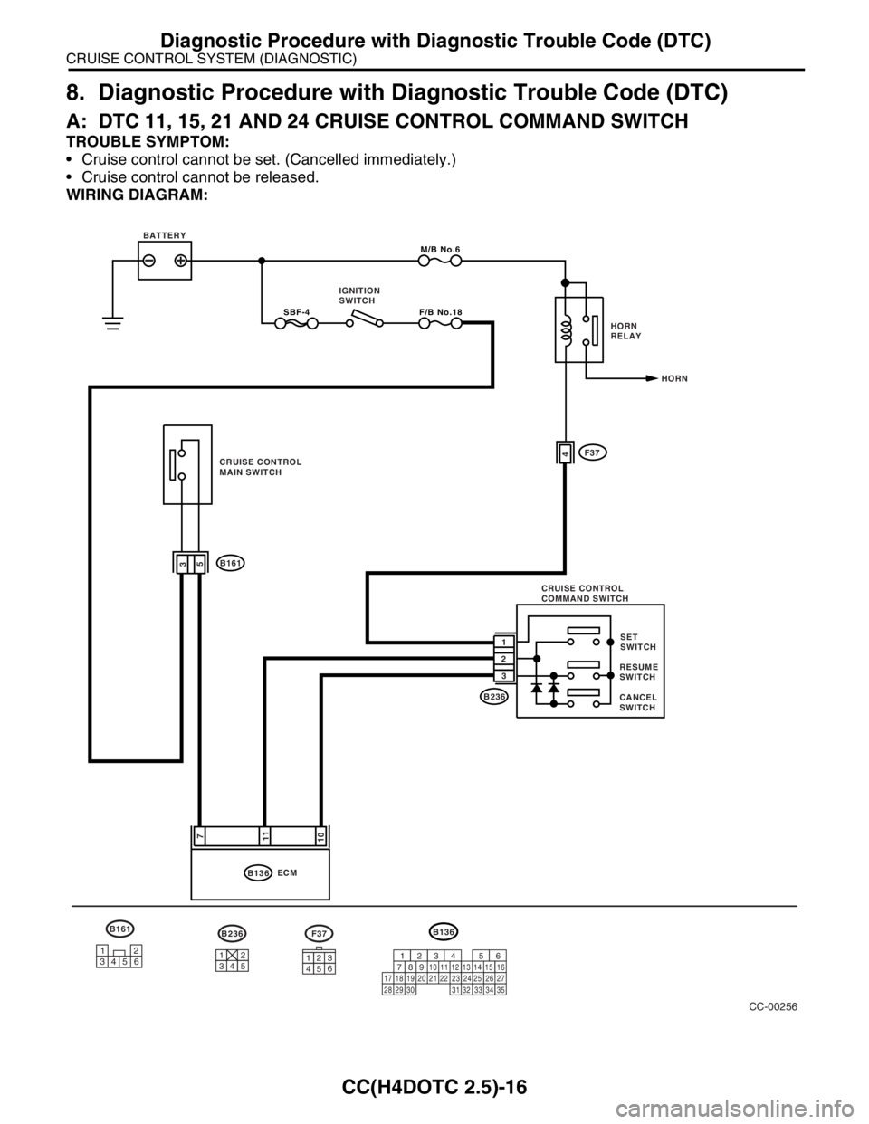
8. Diagnostic Procedure with Diagnostic Trouble Code (DTC)
A: DTC 11, 15, 21 AND 24 CRUISE CONTROL COMMAND SWITCH
TROUBLE SYMPTOM:
Cruise control cannot be set. (Cancelled immediately.)
Cruise control cannot be released.
WIRING DIAGRAM:
CC-00256
F37B236
31264531245
B136
9
30 29 28 323120 19 18 22211012
1114
24
34 3327
261612345613
2315
25871735
B136M/B No.6
10113
B2361SET
SWITCH
CANCEL
SWITCHRESUME
SWITCH SBF-4F/B No.18
7
ECM BATTERY
HORN IGNITION
SWITCH
5
CRUISE CONTROL
MAIN SWITCH4
B161
2
3CRUISE CONTROL
COMMAND SWITCHF37HORN
RELAY
B161
12
3456
Page 629 of 2870

CC(H4DOTC 2.5)-17
CRUISE CONTROL SYSTEM (DIAGNOSTIC)
Diagnostic Procedure with Diagnostic Trouble Code (DTC)
Step Check Yes No
1 CHECK CRUISE CONTROL MAIN SWITCH
CIRCUIT.
1) Turn the ignition switch to OFF.
2) Disconnect the ECM harness connector.
3) Turn the ignition switch to ON.
4) Measure the voltage between harness con-
nector terminal and chassis ground when the
main switch is pressed and is not pressed.
Connector & terminal
(B136) No. 7 (+) — Chassis ground (
−):Is the voltage 0 V when the
main switch is not pressed? Is
the voltage more than 10 V
when the main switch is
pressed?Go to step 2. Check the fuse
No. 18 (in fuse &
relay box).
Check the har-
ness for open or
short between
cruise control
command switch
and fuse & relay
box. If no malfunc-
tion is found after
checking above,
Go to step 6.
2 CHECK SET/COAST SWITCH CIRCUIT.
1) Turn the ignition switch to OFF.
2) Disconnect the ECM harness connector.
3) Measure the voltage between harness con-
nector terminal and chassis ground when SET/
COAST switch is pressed and not pressed.
Connector & terminal
(B136) No. 11 (+) — Chassis ground (
−):Is the voltage 0 V when SET/
COAST switch is not pressed?
Is the voltage more than 10 V
when SET/COAST switch is
pressed?Go to step 3.Go to step 5.
3 CHECK RESUME/ACCEL SWITCH CIRCUIT.
Measure the voltage between harness connec-
tor terminal and chassis ground when
RESUME/ACCEL switch is pressed and not
pressed.
Connector & terminal
(B136) No. 10 (+) — Chassis ground (
−):Is the voltage 0 V when
RESUME/ACCEL switch is not
pressed? Is the voltage more
than 10 V when RESUME/
ACCEL switch is pressed?Go to step 4.Go to step 5.
4 CHECK CANCEL SWITCH CIRCUIT.
Measure the voltage between harness connec-
tor terminal and chassis ground when CAN-
CEL switch is pressed and not pressed.
Connector & terminal
(B136) No. 10 (+) — Chassis ground (
−):
(B136) No. 11 (+) — Chassis ground (
−): Is the voltage 0 V when CAN-
CEL switch is not pressed? Is
the voltage more than 10 V
when CANCEL switch is
pressed?Cruise control
command switch
circuit is OK.Go to step 5.
5 CHECK POWER SUPPLY FOR COMMAND
SWITCH.
Check the horn operation.Does the horn sound? Go to step 6. Check the fuse
No. 6 (in main fuse
box).
Check the horn
relay.
RELAY, INSPEC-
TION, Horn Sys-
tem.>
Check the har-
ness for open or
short between
cruise control
command switch
and fuse & relay
box.
6 CHECK CRUISE CONTROL COMMAND
SWITCH.
Remove and check the cruise control com-
mand switch.
switch OK?Check the harness
between cruise
control command
switch and ECM.Replace the cruise
control command
switch.
Page 630 of 2870

CC(H4DOTC 2.5)-18
CRUISE CONTROL SYSTEM (DIAGNOSTIC)
Diagnostic Procedure with Diagnostic Trouble Code (DTC)
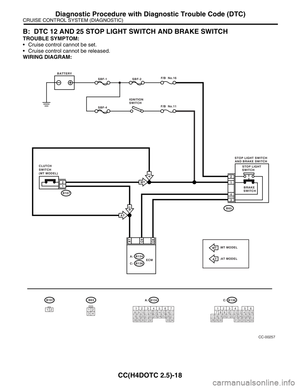
B: DTC 12 AND 25 STOP LIGHT SWITCH AND BRAKE SWITCH
TROUBLE SYMPTOM:
Cruise control cannot be set.
Cruise control cannot be released.
WIRING DIAGRAM:
CC-00257
B107B65
12
SBF-1SBF-2F/B No.16
2
1
B65
B1071
3
4
2
C8A1
C9
1234
STOP LIGHT
SWITCH CLUTCH
SWITCH
(MT MODEL)BATTERY
B134
A:
B136
C:ECM
B134
9
30 29 28 323120 19 18 222110 121114
24
34 3327 2617 16123456713
2315
258
B136
9
30 29 28 323120 19 18 22211012
1114
24
34 3327
261612345613
2315
25871735
C: A:
SBF-4F/B No.11
IGNITION
SWITCH
BRAKE
SWITCH STOP LIGHT SWITCH
AND BRAKE SWITCH
AT
:MT MODEL
:AT MODEL
AT
MT
MT
MT
AT
Page 631 of 2870

CC(H4DOTC 2.5)-19
CRUISE CONTROL SYSTEM (DIAGNOSTIC)
Diagnostic Procedure with Diagnostic Trouble Code (DTC)
Step Check Yes No
1 CHECK STOP LIGHT SWITCH AND BRAKE
SWITCH CIRCUIT.
1) Turn the ignition switch to OFF.
2) Disconnect the stop light switch and brake
switch harness connector.
3) Turn the ignition switch to ON.
4) Measure the voltage between harness con-
nector terminal and chassis ground.
Connector & terminal
(B65) No. 2 (+) — Chassis ground (
−): Is the voltage more than 10 V? Go to step 2. Check the fuse
No. 16 (in fuse &
relay box).
Check the har-
ness for open or
short between
stop light/brake
switch and fuse &
relay box.
2 CHECK STOP LIGHT SWITCH AND BRAKE
SWITCH CIRCUIT.
Measure the voltage between harness connec-
tor terminal and chassis ground.
Connector & terminal
(B65) No. 1 (+) — Chassis ground (
−): Is the voltage more than 10 V? Go to step 3. Check the fuse
No. 11 (in fuse &
relay box).
Check the har-
ness for open or
short between
stop light/brake
switch and fuse &
relay box.
Check the clutch
switch and circuit.
3 CHECK STOP LIGHT SWITCH AND BRAKE
SWITCH CIRCUIT.
1) Turn the ignition switch to OFF.
2) Disconnect the ECM harness connector.
3) Measure the resistance between ECM har-
ness connector terminal and stop light switch
and brake switch harness connector terminal.
Connector & terminal
(B136) No. 8 — (B65) No. 3:
(B136) No. 9 — (B65) No. 4: Is the resistance less than 10
Ω? Go to step 4.Repair the har-
ness.
4 CHECK STOP LIGHT SWITCH AND BRAKE
SWITCH.
Remove and check the stop light switch and
brake switch.
brake switch OK? Stop light switch
and brake switch
circuit are OK.Replace the stop
light switch and
brake switch.
Page 632 of 2870

CC(H4DOTC 2.5)-20
CRUISE CONTROL SYSTEM (DIAGNOSTIC)
Diagnostic Procedure with Diagnostic Trouble Code (DTC)
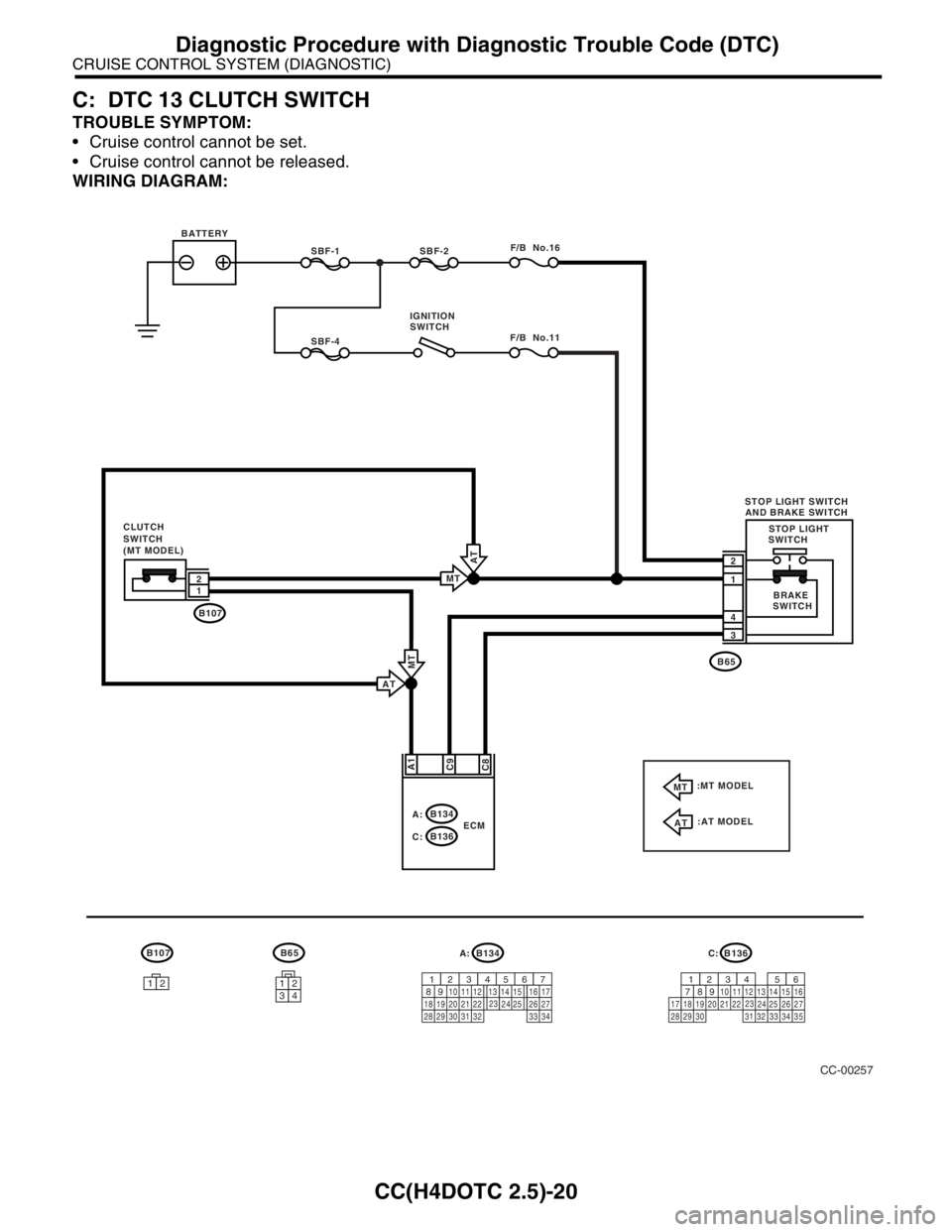
C: DTC 13 CLUTCH SWITCH
TROUBLE SYMPTOM:
Cruise control cannot be set.
Cruise control cannot be released.
WIRING DIAGRAM:
CC-00257
B107B65
12
SBF-1SBF-2F/B No.16
2
1
B65
B1071
3
4
2
C8A1
C9
1234
STOP LIGHT
SWITCH CLUTCH
SWITCH
(MT MODEL)BATTERY
B134
A:
B136
C:ECM
B134
9
30 29 28 323120 19 18 222110 121114
24
34 3327 2617 16123456713
2315
258
B136
9
30 29 28 323120 19 18 22211012
1114
24
34 3327
261612345613
2315
25871735
C: A:
SBF-4F/B No.11
IGNITION
SWITCH
BRAKE
SWITCH STOP LIGHT SWITCH
AND BRAKE SWITCH
AT
:MT MODEL
:AT MODEL
AT
MT
MT
MT
AT
Page 633 of 2870

CC(H4DOTC 2.5)-21
CRUISE CONTROL SYSTEM (DIAGNOSTIC)
Diagnostic Procedure with Diagnostic Trouble Code (DTC)
Step Check Yes No
1 CHECK CLUTCH SWITCH CIRCUIT.
1) Turn the ignition switch to OFF.
2) Disconnect the clutch switch harness con-
nector.
3) Turn the ignition switch to ON.
4) Measure the voltage between harness con-
nector terminal and chassis ground.
Connector & terminal
(B107) No. 2 (+) — Chassis ground (
−):Is the voltage more than 10 V? Go to step 2. Check the fuse
No. 11 (fuse &
relay box).
Check the har-
ness for open or
short between
clutch switch and
fuse & relay box.
2 CHECK CLUTCH SWITCH CIRCUIT.
1) Turn the ignition switch to OFF.
2) Disconnect the ECM harness connector.
3) Measure the resistance between clutch
switch harness connector terminal and ECM
harness connector terminal.
Connector & terminal
(B107) No. 1 — (B134) No. 1:Is the resistance less than 10
Ω? Go to step 3.Repair the har-
ness.
3 CHECK CLUTCH SWITCH.
Remove and check the clutch switch.
cuit is OK.Replace the clutch
switch.