Page 427 of 2870

SL-7
SECURITY AND LOCK
General Description
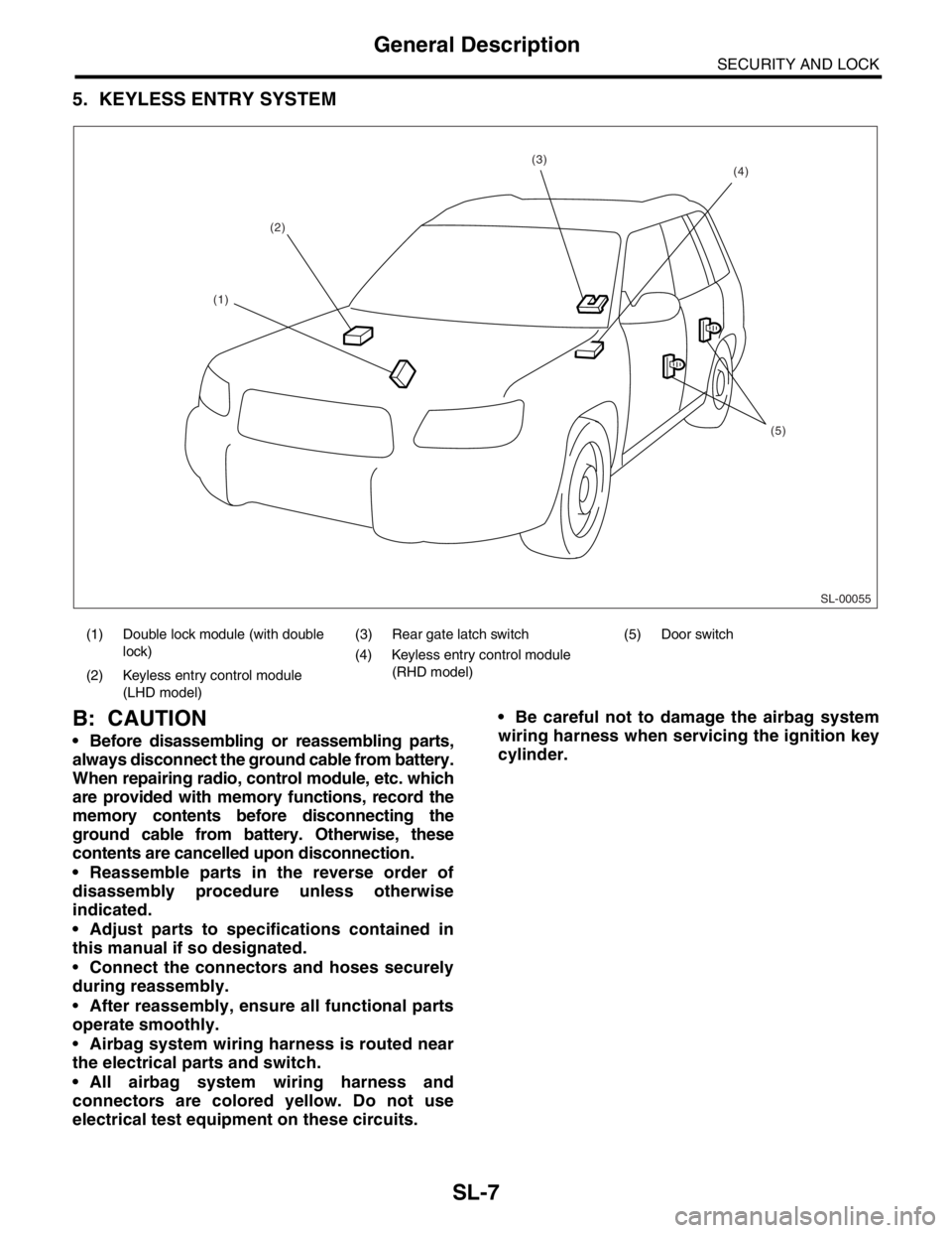
5. KEYLESS ENTRY SYSTEM
B: CAUTION
Before disassembling or reassembling parts,
always disconnect the ground cable from battery.
When repairing radio, control module, etc. which
are provided with memory functions, record the
memory contents before disconnecting the
ground cable from battery. Otherwise, these
contents are cancelled upon disconnection.
Reassemble parts in the reverse order of
disassembly procedure unless otherwise
indicated.
Adjust parts to specifications contained in
this manual if so designated.
Connect the connectors and hoses securely
during reassembly.
After reassembly, ensure all functional parts
operate smoothly.
Airbag system wiring harness is routed near
the electrical parts and switch.
All airbag system wiring harness and
connectors are colored yellow. Do not use
electrical test equipment on these circuits. Be careful not to damage the airbag system
wiring harness when servicing the ignition key
cylinder.
(1) Double lock module (with double
lock)(3) Rear gate latch switch (5) Door switch
(4) Keyless entry control module
(RHD model)
(2) Keyless entry control module
(LHD model)
SL-00055
(2)
(5)
(4)(3)
(1)
Page 428 of 2870
SL-8
SECURITY AND LOCK
General Description
C: PREPARATION TOOL
1. SPECIAL TOOL
2. GENERAL TOOL
ILLUSTRATION TOOL NUMBER DESCRIPTION REMARKS
925580000 PULLER Used for removing trim clip.
TOOL NAME REMARKS
Circuit tester Used for measuring resistance and voltage.
Drill Used for replacing ignition key lock.
ST-925580000
Page 434 of 2870

SL-14
SECURITY AND LOCK
Keyless Entry System
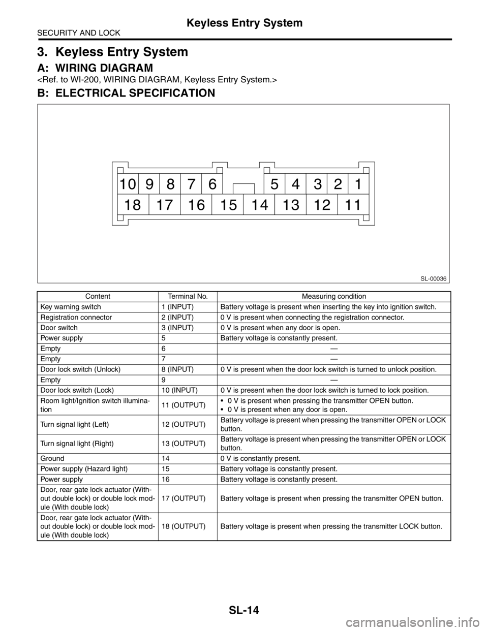
3. Keyless Entry System
A: WIRING DIAGRAM
B: ELECTRICAL SPECIFICATION
Content Terminal No. Measuring condition
Key warning switch 1 (INPUT) Battery voltage is present when inserting the key into ignition switch.
Registration connector 2 (INPUT) 0 V is present when connecting the registration connector.
Door switch 3 (INPUT) 0 V is present when any door is open.
Power supply 5 Battery voltage is constantly present.
Empty 6 —
Empty 7 —
Door lock switch (Unlock) 8 (INPUT) 0 V is present when the door lock switch is turned to unlock position.
Empty 9 —
Door lock switch (Lock) 10 (INPUT) 0 V is present when the door lock switch is turned to lock position.
Room light/Ignition switch illumina-
tion11 (OUTPUT) 0 V is present when pressing the transmitter OPEN button.
0 V is present when any door is open.
Turn signal light (Left) 12 (OUTPUT)Battery voltage is present when pressing the transmitter OPEN or LOCK
button.
Turn signal light (Right) 13 (OUTPUT)Battery voltage is present when pressing the transmitter OPEN or LOCK
button.
Ground 14 0 V is constantly present.
Power supply (Hazard light) 15 Battery voltage is constantly present.
Power supply 16 Battery voltage is constantly present.
Door, rear gate lock actuator (With-
out double lock) or double lock mod-
ule (With double lock)17 (OUTPUT) Battery voltage is present when pressing the transmitter OPEN button.
Door, rear gate lock actuator (With-
out double lock) or double lock mod-
ule (With double lock)18 (OUTPUT) Battery voltage is present when pressing the transmitter LOCK button.
SL-00036
1 2 3 4 5 6 7 8 9 10
11 12 13 14 15 16 17 18
Page 436 of 2870

SL-16
SECURITY AND LOCK
Keyless Entry System
2. CHECK TRANSMITTER BATTERY
3. CHECK FUSE
The room light and ignition switch illu-
mination operation does not activate.1. Check the room light operation.
LIGHT OPERATION, INSPECTION,
Keyless Entry System.>
2. Check the ignition switch illumination circuit.
SWITCH ILLUMINATION CIRCUIT,
INSPECTION, Keyless Entry Sys-
tem.>
3. Replace the keyless entry control module.
(without double lock)
Module.>
4. Replace the double lock module. (with double
lock)
ule.>
Step Check Yes No
1 CHECK TRANSMITTER BATTERY.
1) Remove the battery from transmitter.
to SL-41, REMOVAL, Keyless Transmitter.>
2) Check the battery voltage.
INSPECTION, Keyless Transmitter.>
NOTE:
If the transmitter battery voltage is 2.5 V or less,
the range of transmission becomes very short.Is the voltage more than 2.5 V? If further inspec-
tion is necessary,
refer to “SYMP-
TOM CHART”.
SYMPTOM
CHART, INSPEC-
TION, Keyless
Entry System.>Replace the trans-
mitter battery.
Step Check Yes No
1 CHECK FUSE.
Remove and visually check the fuse No. 2 (in
the main fuse box), No. 3 (in the fuse and relay
box) and SBF-6 (in the main fuse box)Is the fuse blown out? Replace the fuse
with a new one.Check the power
supply and ground
circuit.
SL-17, CHECK
POWER SUPPLY
AND GROUND
CIRCUIT,
INSPECTION,
Keyless Entry Sys-
tem.> Symptom Repair order Reference
Page 439 of 2870

SL-19
SECURITY AND LOCK
Keyless Entry System
7. CHECK KEY WARNING SWITCH
Step Check Yes No
1 CHECK FUSE.
Remove and visually check the fuse No. 6 (in
the main fuse box).Is the fuse blown out? Go to step 2.Replace the fuse
with a new one.
2 CHECK KEY WARNING SWITCH CIRCUIT.
1) Disconnect the keyless entry control mod-
ule harness connector.
2) Insert the key into ignition switch. (LOCK
position)
3) Measure the voltage between harness con-
nector terminal and chassis ground.
Connector & terminal
(B176) No. 1 (+) — Chassis ground (
−):Is the voltage more than 10 V? Go to step 3.Go to step 4.
3 CHECK KEY WARNING SWITCH CIRCUIT.
1) Remove the key from ignition switch.
2) Measure the voltage between harness con-
nector terminal and chassis ground.
NOTE:
The voltage is not 0 V due to noise, etc.
Connector & terminal
(B176) No. 1 (+) — Chassis ground (
−):Is the voltage approx. less than
0 V?The key warning
switch is OK.Go to step 4.
4 CHECK KEY WARNING SWITCH.
1) Disconnect the key warning switch harness
connector.
2) Insert the key into ignition switch. (LOCK
position)
3) Measure the resistance between key warn-
ing switch terminals.
Te r m i n a l
No. 1 — No. 2:Is the resistance less than 1
Ω?Go to step 5.Replace the key
warning switch.
5 CHECK KEY WARNING SWITCH.
1) Remove the key from ignition switch.
2) Measure the resistance between key warn-
ing switch terminals.
Te r m i n a l
No. 1 — No. 2:Is the resistance less than 1
MΩ?Check the follow-
ing:
Harness for
open circuits or
shorts between
the key warn-
ing switch and
fuse
Harness for
open circuits
and shorts
between the
keyless entry
control module
and key warn-
ing switchReplace the key
warning switch.
Page 440 of 2870

SL-20
SECURITY AND LOCK
Keyless Entry System
8. CHECK HAZARD LIGHT OPERATION
9. CHECK ROOM LIGHT OPERATION
Step Check Yes No
1 CHECK HAZARD LIGHT OPERATION.
Make sure the hazard light blinks when hazard
switch is turned ON.Does the hazard light blink? Go to step 2.Check the hazard
light circuit.
2 CHECK OUTPUT SIGNAL.
1) Remove the key from ignition switch.
2) Close all doors and rear gate.
3) Measure the voltage between keyless entry
control module harness connector terminal
and chassis ground when LOCK or OPEN but-
ton of transmitter is pressed.
Connector & terminal
(B176) No. 12, No. 13 (+) — Chassis
ground (
−):Is the voltage more than 10 V? Check the harness
for open or short
between keyless
entry control mod-
ule and turn signal
lights.Replace the key-
less entry control
module.
Step Check Yes No
1 CHECK ROOM LIGHT OPERATION.
Make sure the room light illuminates when the
room light switch is turned ON.Does the room light illuminate? Go to step 2.Check the room
light circuit.
2 CHECK HARNESS BETWEEN ROOM LIGHT
AND KEYLESS ENTRY CONTROL MODULE
(WITHOUT DOUBLE LOCK) OR DOUBLE
LOCK MODULE (WITH DOUBLE LOCK).
1) Disconnect the keyless entry control mod-
ule or double lock module harness connector
and room light harness connector.
2) Measure the resistance between keyless
entry control module or double lock module
harness connector terminal and room light har-
ness connector terminal.
Connector & terminal
Without double lock:
(B176) No. 11 — (R52) No. 2:
With double lock:
(B325) No. 1 — (R52) No. 2:Is the resistance less than 10
Ω?The room light
operation circuit is
OK.Check the harness
for open circuits or
shorts between
keyless entry con-
trol module (With-
out double lock) or
double lock mod-
ule (With double
lock) and room
light.
Page 441 of 2870

SL-21
SECURITY AND LOCK
Keyless Entry System
10.CHECK IGNITION SWITCH ILLUMINATION CIRCUIT
11.CHECK OUTPUT SIGNAL TO DOUBLE LOCK MODULE
Step Check Yes No
1 CHECK IGNITION SWITCH ILLUMINATION
POWER SUPPLY.
1) Disconnect the ignition switch illumination
harness connector.
2) Measure the voltage between ignition
switch illumination harness connector terminal
and chassis ground.
Connector & terminal
(B224) No. 1 (+) — Chassis ground (
−):Is the voltage more than 10 V? Go to step 2.Check the harness
for open circuit or
shorts between
ignition switch illu-
mination and fuse.
2 CHECK HARNESS BETWEEN IGNITION
SWITCH ILLUMINATION AND KEYLESS EN-
TRY CONTROL MODULE (WITHOUT DOU-
BLE LOCK) OR DOUBLE LOCK MODULE
(WITH DOUBLE LOCK).
1) Disconnect the keyless entry control mod-
ule or double lock module harness connector.
2) Measure the resistance between keyless
entry or double lock module harness connector
terminal and ignition switch illumination har-
ness connector.
Connector & terminal
Without double lock:
(B176) No. 11 — (R224) No. 1:
With double lock:
(B325) No. 1 — (R224) No. 2:Is the resistance less than 10
Ω?Check the ignition
switch illumina-
tion. If NG, replace
the ignition switch
illumination.Repair the har-
ness.
Step Check Yes No
1 CHECK OUTPUT SIGNAL.
Measure the voltage between the keyless
entry control module harness connector termi-
nal and chassis ground when OPEN button of
transmitter is pressed.
Connector & terminal
(B176) No. 17 (+) — Chassis ground (
−):Is the voltage more than 10 V? Go to step 2.Replace the key-
less entry control
module.
2 CHECK OUTPUT SIGNAL.
Measure the voltage between the keyless
entry control module harness connector termi-
nal and chassis ground when LOCK button of
transmitter is pressed.
Connector & terminal
(B176) No. 18 (+) — Chassis ground (–):Is the voltage more than 10 V? Replace the dou-
ble lock module.Check the harness
for open circuit or
shorts between
the keyless entry
control module
and double lock
module.
Page 455 of 2870
SL-35
SECURITY AND LOCK
Ignition Key Lock
17.Ignition Key Lock
A: REPLACEMENT
1) Remove the ground cable from battery.
2) Remove the steering column.
REMOVAL, Tilt Steering Column.>
3) Secure the steering column in a vise. Remove
the bolt with a drill.
4) Remove the ignition key lock.
5) Use a new torn bolt. Tighten the torn bolt to end
of thread.
B: INSPECTION
1) Remove the instrument panel lower cover.
2) Remove the lower column cover.
3) Unfasten the holddown clip which secures harness
and disconnect the connector of ignition switch from
body harness.
4) Turn the ignition key plate to each position and
check the continuity between terminals of ignition
connector.
If NG, replace the ignition switch.
Switch position Terminal No. Standard
LOCK — —
ACC No. 1 and No. 2 Less than 1 Ω
ON No. 1 and No. 2
No. 1 and No. 4
No. 2 and No. 4Less than 1 Ω
ST No. 1 and No. 3
No. 1 and No. 4
No. 3 and No. 4Less than 1 Ω
SL-00024
SL-00025