Page 561 of 2870

CC-9
CRUISE CONTROL SYSTEM
Cruise Control Command Switch
5. Cruise Control Command
Switch
A: REMOVAL
WARNING:
Before servicing, be sure to read the notes in
the AB section for proper handling of the driv-
er’s airbag module.
General Description.>
1) Set the front wheels in straight ahead position.
2) Turn the ignition switch to OFF.
3) Disconnect the ground cable from battery and
wait for at least 20 seconds before starting work.
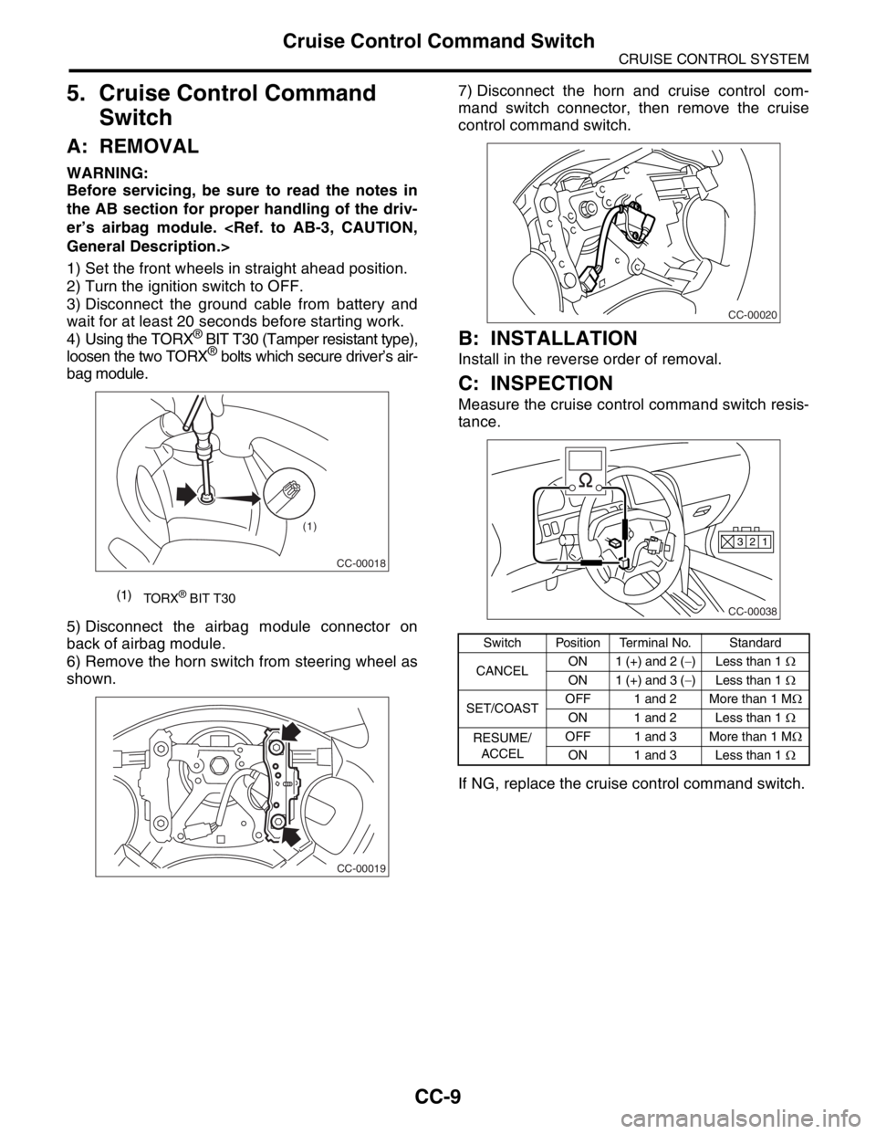
4) Using the TORX
® BIT T30 (Tamper resistant type),
loosen the two TORX® bolts which secure driver’s air-
bag module.
5) Disconnect the airbag module connector on
back of airbag module.
6) Remove the horn switch from steering wheel as
shown.7) Disconnect the horn and cruise control com-
mand switch connector, then remove the cruise
control command switch.
B: INSTALLATION
Install in the reverse order of removal.
C: INSPECTION
Measure the cruise control command switch resis-
tance.
If NG, replace the cruise control command switch.
(1)
TORX® BIT T30
CC-00018
(1)
CC-00019
Switch Position Terminal No. Standard
CANCELON 1 (+) and 2 (−) Less than 1 Ω
ON 1 (+) and 3 (−) Less than 1 Ω
SET/COASTOFF 1 and 2 More than 1 MΩ
ON 1 and 2 Less than 1 Ω
RESUME/
ACCELOFF 1 and 3 More than 1 MΩ
ON 1 and 3 Less than 1 Ω
CC-00020
CC-00038
1 2 3
Page 575 of 2870

CC(H4SO)-7
CRUISE CONTROL SYSTEM (DIAGNOSTIC)
Cruise Control Module I/O Signal
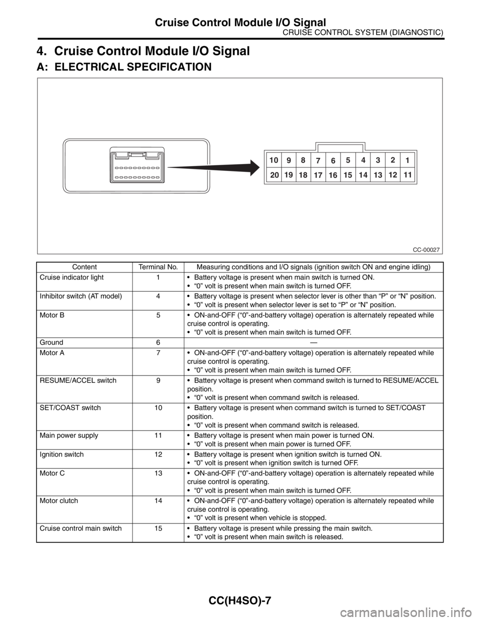
4. Cruise Control Module I/O Signal
A: ELECTRICAL SPECIFICATION
Content Terminal No. Measuring conditions and I/O signals (ignition switch ON and engine idling)
Cruise indicator light 1 Battery voltage is present when main switch is turned ON.
“0” volt is present when main switch is turned OFF.
Inhibitor switch (AT model) 4 Battery voltage is present when selector lever is other than “P” or “N” position.
“0” volt is present when selector lever is set to “P” or “N” position.
Motor B 5 ON-and-OFF (“0”-and-battery voltage) operation is alternately repeated while
cruise control is operating.
“0” volt is present when main switch is turned OFF.
Ground 6 —
Motor A 7 ON-and-OFF (“0”-and-battery voltage) operation is alternately repeated while
cruise control is operating.
“0” volt is present when main switch is turned OFF.
RESUME/ACCEL switch 9 Battery voltage is present when command switch is turned to RESUME/ACCEL
position.
“0” volt is present when command switch is released.
SET/COAST switch 10 Battery voltage is present when command switch is turned to SET/COAST
position.
“0” volt is present when command switch is released.
Main power supply 11 Battery voltage is present when main power is turned ON.
“0” volt is present when main power is turned OFF.
Ignition switch 12 Battery voltage is present when ignition switch is turned ON.
“0” volt is present when ignition switch is turned OFF.
Motor C 13 ON-and-OFF (“0”-and-battery voltage) operation is alternately repeated while
cruise control is operating.
“0” volt is present when main switch is turned OFF.
Motor clutch 14 ON-and-OFF (“0”-and-battery voltage) operation is alternately repeated while
cruise control is operating.
“0” volt is present when vehicle is stopped.
Cruise control main switch 15 Battery voltage is present while pressing the main switch.
“0” volt is present when main switch is released.
CC-00027
10
98
765432
1
2019
18
17 1615 14 1312 11
Page 576 of 2870

CC(H4SO)-8
CRUISE CONTROL SYSTEM (DIAGNOSTIC)
Cruise Control Module I/O Signal
B: WIRING DIAGRAM
Brake switch/Clutch switch
(MT model)16 Leave clutch pedal released (MT model), while cruise control main switch is
turned ON.
Then check that;
Battery voltage is present when brake pedal is released.
“0” volt is present when brake pedal is depressed.
Additionally only in MT model, keep the cruise control main switch to ON and
leave brake pedal released.
Then check that;
Battery voltage is present when clutch pedal is released.
“0” volt is present when clutch pedal is depressed.
Data link connector 17 —
Data link connector 18 —
Vehicle speed sensor (MT
model)
TCM (AT model)19 Lift-up the vehicle until all four wheels are raised off ground, and then rotate any
wheel manually.
Approx. “5” and “0” volt pulse signals are alternately input to cruise control mod-
ule.
Stop light switch 20 Turn ignition switch to OFF.
Then check that;
Battery voltage is present when brake pedal is depressed.
“0” volt is present when brake pedal is released.
NOTE:
Voltage at terminals 5, 7, 13 and 14 cannot be checked unless vehicle is driving by cruise control operation.Content Terminal No. Measuring conditions and I/O signals (ignition switch ON and engine idling)
Page 578 of 2870

CC(H4SO)-10
CRUISE CONTROL SYSTEM (DIAGNOSTIC)
Subaru Select Monitor
6) Turn the Subaru Select Monitor switch to ON.
7) On the Main Menu display screen, select the {All
System Diagnosis} and press [YES] key.
NOTE:
DTC is also shown in the {Each System Check} mode.
This mode is called up on the Cruise Control Diagnosis
screen by selecting the item {Cancel Code(s) Display}.
8) Drive the vehicle at least 30 km/h (19 MPH) with
cruise speed set.
9) If the cruise speed is canceled itself (without do-
ing any cancel operations), DTC will appear on se-
lect monitor display.
CAUTION:
DTC will also appear when cruise cancel is ef-
fected by driver. Do not confuse.
Have a co-worker ride in the vehicle to assist
in diagnosis during driving.
NOTE:
DTC will be cleared by turning the ignition switch or
cruise control main switch to OFF.3. REAL-TIME DIAGNOSIS
1) Connect the select monitor.
2) Turn the ignition switch and cruise control main
switch to ON.
3) Turn the Subaru Select Monitor switch to ON.
4) On the Main Menu display screen, select the
{Each System Check} and press [YES] key.
5) On the System Selection Menu display screen,
select the {Cruise Control} and press [YES] key.
6) Press the [YES] key after displayed the informa-
tion of engine type.
7) On the Cruise Control Diagnosis display screen,
select the {Current Data Display & Save} and press
[YES] key.
8) Make sure that normal indication is displayed
when controls are operated as indicated below:
Depress/release the brake pedal. (Stop light
switch and brake switch turn ON or OFF.)
Turn ON or OFF the “SET/COAST” switch.
Turn ON or OFF the “RESUME/ACCEL” switch.
Depress/release the clutch pedal. (MT model)
Set the selector lever to P or N. (AT model)
NOTE:
For detailed operation procedure, refer to the
SUBARU SELECT MONITOR OPERATION MAN-
UAL.
For detailed concerning DTC, refer to the List of
Diagnostic Trouble Code (DTC).
Code (DTC).>
(1) Power switch
CC-00045
(1)
Page 581 of 2870
CC(H4SO)-13
CRUISE CONTROL SYSTEM (DIAGNOSTIC)
Diagnostic Procedure with Symptom
B: CHECK POWER SUPPLY
TROUBLE SYMPTOM:
Cruise control can be set normally, but indicator does not come on. (When main switch is pressed.)
WIRING DIAGRAM:
CC-00253
B161
i3
i10 B:B94
12345678910
11 12 13 14 15 16 17 18 19 20
E
11115126
5
3
7
B16
B9
BATTERY
CRUISE CONTROL MODULE CRUISE CONTROL
MAIN SWITCH
CRUISE
INDICATOR
LIGHT
COMBINATION
METER
SBF-4F/B No.18
B94
B161
F/B No.14
IGNITION
SWITCH
i10
i3
B38
i3B38
B:
i10
B:
123456789101112131415161718192021222324252627282930
219
32
1234 5610 11 12 13 14 15716
23 3019 20
22 26 27 28 29817
24 3118
25
: INDICATOR ON
COMBINATION METER
4
3
1
2
IC
IS
ISIS
IC
IC
IC
IS
IC
: INDICATOR ON
MAIN SWITCH IS
16
12
3456
Page 582 of 2870
CC(H4SO)-14
CRUISE CONTROL SYSTEM (DIAGNOSTIC)
Diagnostic Procedure with Symptom
Step Check Yes No
1 CHECK POWER SUPPLY.
1) Turn the ignition switch to OFF.
2) Disconnect the cruise control module har-
ness connector.
3) Turn the ignition switch to ON.
4) Measure the voltage between harness con-
nector terminal and chassis ground.
Connector & terminal
(B94) No. 12 (+) — Chassis ground (
−):Is the voltage more than 10 V? Go to step 2. Check the fuse
No. 18 (in fuse &
relay box).
Check the har-
ness for open or
short between
cruise control
module and fuse &
relay box.
2 CHECK GROUND CIRCUIT.
1) Turn the ignition switch OFF.
2) Measure the resistance between harness
connector terminal and chassis ground.
Connector & terminal
(B94) No. 6 — Chassis ground:Is the resistance less than 10
Ω?Power supply and
ground circuit are
OK.Repair the har-
ness.
Page 583 of 2870

CC(H4SO)-15
CRUISE CONTROL SYSTEM (DIAGNOSTIC)
Diagnostic Procedure with Symptom
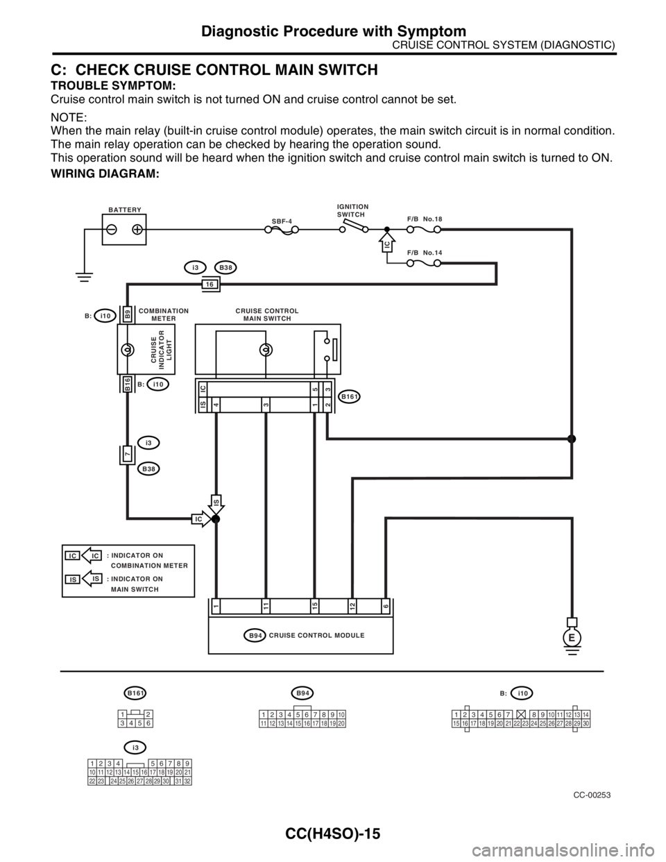
C: CHECK CRUISE CONTROL MAIN SWITCH
TROUBLE SYMPTOM:
Cruise control main switch is not turned ON and cruise control cannot be set.
NOTE:
When the main relay (built-in cruise control module) operates, the main switch circuit is in normal condition.
The main relay operation can be checked by hearing the operation sound.
This operation sound will be heard when the ignition switch and cruise control main switch is turned to ON.
WIRING DIAGRAM:
CC-00253
B161
i3
i10 B:B94
12345678910
11 12 13 14 15 16 17 18 19 20
E
11115126
5
3
7
B16
B9
BATTERY
CRUISE CONTROL MODULE CRUISE CONTROL
MAIN SWITCH
CRUISE
INDICATOR
LIGHT
COMBINATION
METER
SBF-4F/B No.18
B94
B161
F/B No.14
IGNITION
SWITCH
i10
i3
B38
i3B38
B:
i10
B:
123456789101112131415161718192021222324252627282930
219
32
1234 5610 11 12 13 14 15716
23 3019 20
22 26 27 28 29817
24 3118
25
: INDICATOR ON
COMBINATION METER
4
3
1
2
IC
IS
ISIS
IC
IC
IC
IS
IC
: INDICATOR ON
MAIN SWITCH IS
16
12
3456
Page 584 of 2870

CC(H4SO)-16
CRUISE CONTROL SYSTEM (DIAGNOSTIC)
Diagnostic Procedure with Symptom
Step Check Yes No
1 CHECK CRUISE CONTROL MAIN SWITCH
CIRCUIT.
1) Turn the ignition switch to OFF.
2) Disconnect the cruise control main switch
harness connector.
3) Turn the ignition switch to ON.
4) Measure the voltage between harness con-
nector terminal and chassis ground.
Connector & terminal
With indicator built in combination
meter:
(B161) No. 3 (+) — Chassis ground (
−):
With indicator built in main switch:
(B161) No. 2 (+) — Chassis ground (
−):Is the voltage more than 10 V? Go to step 2. Check the fuse
No. 18 (in fuse &
relay box).
Check the har-
ness for open or
short between
cruise control main
switch and fuse &
relay box.
2 CHECK CRUISE CONTROL MAIN SWITCH
CIRCUIT.
1) Turn the ignition switch OFF.
2) Disconnect the cruise control module har-
ness connector.
3) Measure the resistance between cruise
control module harness connector terminal
and cruise control main switch harness con-
nector terminal.
Connector & terminal
With indicator built in combination
meter:
(B94) No. 15 — (B161) No. 5:
With indicator built in main switch:
(B94) No. 15 — (B161) No. 1:Is the resistance less than 10
Ω?Go to step 3.Repair the har-
ness.
3 CHECK CRUISE CONTROL MAIN SWITCH.
Remove and check the cruise control main
switch.
Switch.>Is the cruise control main
switch OK?Replace the cruise
control module.Replace the cruise
control main
switch.