2004 SUBARU FORESTER ignition
[x] Cancel search: ignitionPage 635 of 2870

CC(H4DOTC 2.5)-23
CRUISE CONTROL SYSTEM (DIAGNOSTIC)
Diagnostic Procedure with Diagnostic Trouble Code (DTC)
Step Check Yes No
1 CHECK TRANSMISSION TYPE.Is the target MT model? Go to step 2.Go to step 5.
2 CHECK NEUTRAL POSITION SWITCH CIR-
CUIT.
1) Turn the ignition switch to OFF.
2) Disconnect the neutral position switch har-
ness connector.
3) Turn the ignition switch to ON.
4) Measure the voltage between harness con-
nector terminal and chassis ground.
Connector & terminal
(B128) No. 1 (+) — Chassis ground (
−): Is the voltage more than 10 V? Go to step 3.Check the harness
for open or short
between neutral
position switch and
ECM.
3 CHECK NEUTRAL POSITION SWITCH CIR-
CUIT.
1) Turn the ignition switch to OFF.
2) Measure the resistance between neutral
position switch harness connector terminal and
chassis ground.
Connector & terminal
(B128) No. 3 — Chassis ground: Is the resistance less than 10
Ω? Go to step 4.Repair the har-
ness.
4 CHECK NEUTRAL POSITION SWITCH.
Remove and check the neutral position switch. Is the neutral position switch
OK? Neutral position
switch circuit is
OK.Replace the neu-
tral position switch.
5 CHECK INHIBITOR SWITCH CIRCUIT.
1) Turn the ignition switch to OFF.
2) Disconnect the inhibitor switch harness
connector.
3) Turn the ignition switch to ON.
4) Measure the voltage between harness con-
nector terminal and chassis ground.
Connector & terminal
(T7) No. 12 (+) — Chassis ground (
−): Is the voltage more than 10 V? Go to step 6.Check the harness
for open or short
between inhibitor
switch and ECM.
6 CHECK INHIBITOR SWITCH CIRCUIT.
1) Turn the ignition switch to OFF.
2) Measure the resistance between inhibitor
switch harness connector terminal and chassis
ground.
Connector & terminal
(T7) No. 7 — Chassis ground: Is the resistance less than 10
Ω? Go to step 7.Repair the har-
ness.
7 CHECK INHIBITOR SWITCH.
Remove and check the inhibitor switch. Is the inhibitor switch OK? Inhibitor switch cir-
cuit is OK.Replace the inhibi-
tor switch.
Page 636 of 2870

CC(H4DOTC 2.5)-24
CRUISE CONTROL SYSTEM (DIAGNOSTIC)
Diagnostic Procedure with Diagnostic Trouble Code (DTC)
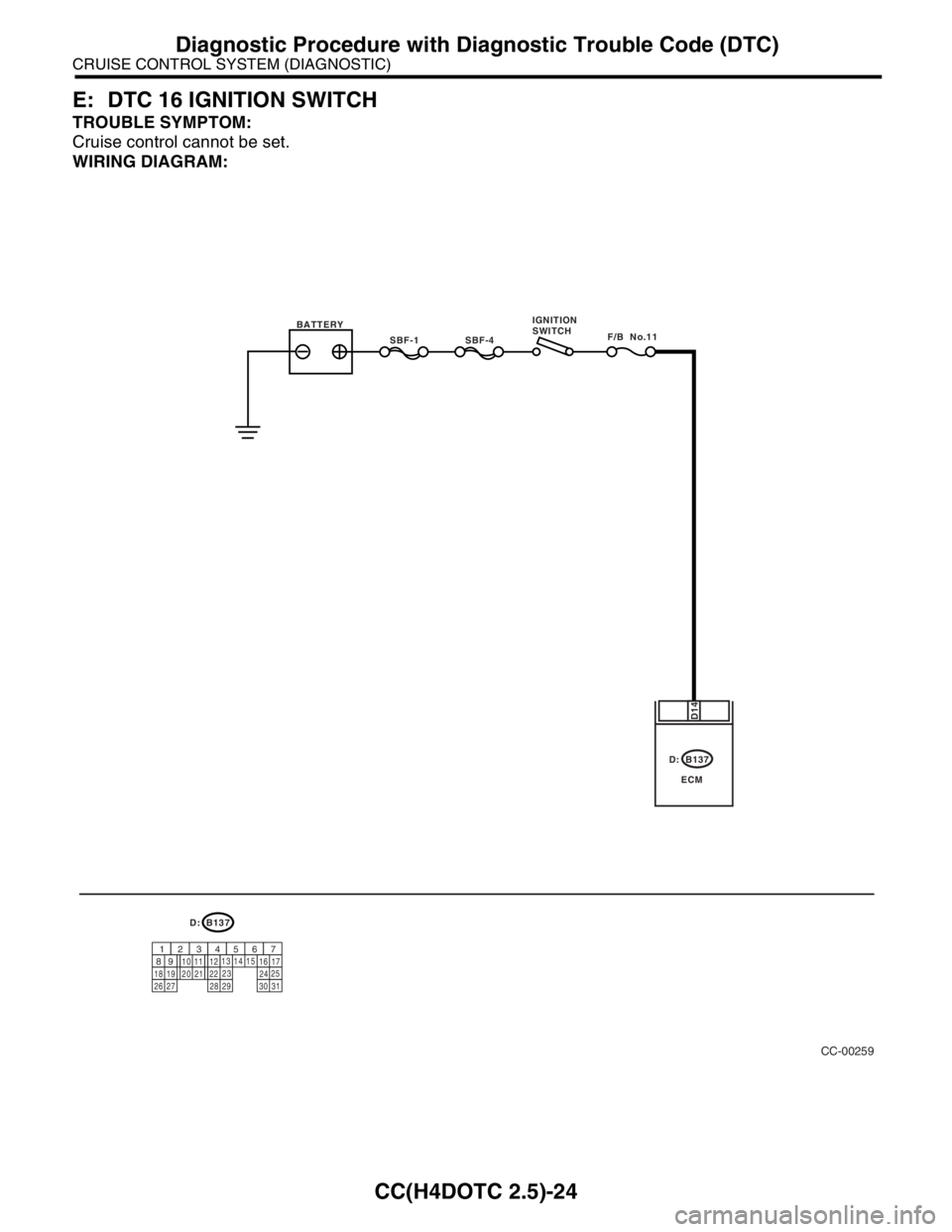
E: DTC 16 IGNITION SWITCH
TROUBLE SYMPTOM:
Cruise control cannot be set.
WIRING DIAGRAM:
CC-00259
B137
ECM
D14
D:
B137
9
30
29 283120 19 18
22
211012
1114
24
27 26
17 16123456713
2315
258D:
SBF-1F/B No.11SBF-4 BATTERYIGNITION
SWITCH
Page 637 of 2870

CC(H4DOTC 2.5)-25
CRUISE CONTROL SYSTEM (DIAGNOSTIC)
Diagnostic Procedure with Diagnostic Trouble Code (DTC)
Step Check Yes No
1 CHECK IGNITION SWITCH CIRCUIT.
1) Turn the ignition switch to OFF.
2) Disconnect the ECM harness connector.
3) Turn the ignition switch to ON.
4) Measure the voltage between harness con-
nector terminal and chassis ground.
Connector & terminal
(B137) No. 14 (+) — Chassis ground (
−): Is the voltage more than 10 V? Check the poor
contact of ECM
connector. Check the fuse
No. 11 (fuse &
relay box).
Check the har-
ness for open or
short between
ignition switch and
ECM.
Page 638 of 2870

CC(H4DOTC 2.5)-26
CRUISE CONTROL SYSTEM (DIAGNOSTIC)
Diagnostic Procedure with Diagnostic Trouble Code (DTC)
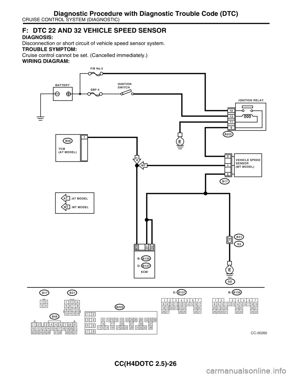
F: DTC 22 AND 32 VEHICLE SPEED SENSOR
DIAGNOSIS:
Disconnection or short circuit of vehicle speed sensor system.
TROUBLE SYMPTOM:
Cruise control cannot be set. (Cancelled immediately.)
WIRING DIAGRAM:
3412
12
789 56 3
410 11 1219 20 21
29 30 31 13
14 151617
27 2818
22 23 24 25 2610111213
1415161718
1920212223
2425262728
2930313233
3435363738
12
934
56
78
B21
123
4
56
78
9
1011 12
1314 15 16
B17B137
9
30
29 283120 19 18
22
211012
1114
24
27 26
17 16123456713
2315
258D:
B56
B225
B135
9
30
29 28312019 18
22 2110
12 1114
2427 2617 16123456713
2315
258B:
32 3334 35
CC-00260
SBF-4
B171
2 3
D2 B26
E
B21
E2
GE B137
ECM D:B135 B: BATTERYIGNITION
SWITCH
VEHICLE SPEED
SENSOR
(MT MODEL) F/B No.5
IGNITION RELAY
10
13
11
9
D1
16
E
B225
B56
TCM
(AT MODEL)1
AT
:AT MODEL
MT
:MT MODELMT
AT
Page 639 of 2870

CC(H4DOTC 2.5)-27
CRUISE CONTROL SYSTEM (DIAGNOSTIC)
Diagnostic Procedure with Diagnostic Trouble Code (DTC)
Step Check Yes No
1 CHECK TRANSMISSION TYPE.Is the target MT model? Go to step 2.Go to step 6.
2 CHECK HARNESS BETWEEN BATTERY
AND VEHICLE SPEED SENSOR.
1) Turn the ignition switch to OFF.
2) Disconnect the harness connector from
vehicle speed sensor.
3) Turn the ignition switch to ON.
4) Measure the voltage between vehicle
speed sensor harness connector terminal and
chassis ground.
Connector & terminal
(B17) No. 3 (+) — Chassis ground (
−):Is the voltage more than 10 V? Go to step 3.Check the harness
for open or short
between fuse and
vehicle speed sen-
sor.
3 CHECK HARNESS BETWEEN ECM AND VE-
HICLE SPEED SENSOR.
1) Turn the ignition switch to OFF.
2) Disconnect the harness connector from
ECM.
3) Measure the resistance between vehicle
speed sensor harness connector terminal and
ECM harness connector terminal.
Connector & terminal
(B17) No. 1 — (B135) No. 26:Is the resistance less than 10
Ω?Go to step 4.Repair the har-
ness.
4 CHECK HARNESS BETWEEN VEHICLE
SPEED SENSOR AND ENGINE GROUND.
1) Turn the ignition switch to OFF.
2) Measure the resistance between vehicle
speed sensor harness connector terminal and
engine ground.
Connector & terminal
(B17) No. 2 — Engine ground:Is the resistance less than 10
Ω?Go to step 5.Repair the har-
ness.
5 CHECK VEHICLE SPEED SENSOR.
1) Connect the harness connector to vehicle
speed sensor.
2) Lift-up the vehicle and support with rigid
racks.
3) Drive the vehicle at speed greater than 20
km/h (12 MPH).
Warning:
Be careful not to be caught up by the run-
ning wheels.
4) Measure the voltage between ECM har-
ness connector terminal and chassis ground.
Connector & terminal
(B135) No. 26 (+) — Chassis ground (
−):Is the voltage 1 V ← → 5 V? Check the poor
contact of ECM
connector.Replace the vehi-
cle speed sensor.
6 CHECK HARNESS BETWEEN ECM AND
TCM.
1) Turn the ignition switch to OFF.
2) Disconnect the harness connector from
ECM and TCM.
3) Measure the resistance between ECM har-
ness connector terminal and TCM harness
connector terminal.
Connector & terminal
(B135) No. 26 — (B56) No. 1:Is the resistance less than 10
Ω?Go to step 7.Repair the har-
ness.
Page 644 of 2870

IM-2
IMMOBILIZER (DIAGNOSTIC)
Basic Diagnostic Procedure
1. Basic Diagnostic Procedure
A: PROCEDURE
Step Check Yes No
1 CHECK ILLUMINATION OF IMMOBILIZER
WARNING LIGHT.
1) Turn the ignition switch to OFF or ACC
position.
2) Wait at least 60 seconds.Does the immobilizer warning
light blink?Go to step 2.Check the immobi-
lizer warning light
circuit.
IMMOBILIZER
WARNING CIR-
CUIT, INSPEC-
TION, Diagnostics
Chart for Immobi-
lizer Warning
Light.>
2 CHECK ILLUMINATION OF IMMOBILIZER
WARNING LIGHT.
Remove the key from ignition switch.Does the immobilizer warning
light begin to blink within 1 sec-
ond after the key is removed?Go to step 3.Check the key
switch circuit.
WARNING
SWITCH CIR-
CUIT, INSPEC-
TION, Diagnostics
Chart for Immobi-
lizer Warning
Light.>
3 CHECK ENGINE START.
Turn the ignition switch to START position.Does the engine start? Go to step 4.Go to step 5.
4 CHECK ILLUMINATION OF IMMOBILIZER
WARNING LIGHT.
Turn the ignition switch to ON.Does the immobilizer warning
light illuminate?Check the immobi-
lizer warning light
circuit.
IMMOBILIZER
WARNING CIR-
CUIT, INSPEC-
TION, Diagnostics
Chart for Immobi-
lizer Warning
Light.>Immobilizer sys-
tem is normal.
5 CHECK INDICATION OF DTC ON DISPLAY.
1) Turn the ignition switch to OFF.
2) Connect the Subaru Select Monitor to data
link connector.
3) Turn the ignition switch and Subaru Select
Monitors witch to ON.
4) Read any DTC on the display. Are DTCs indicated on dis-
play?Go to step 6.Repair the related
parts.
6 PERFORM THE DIAGNOSIS.
1) Inspect using “Diagnostics Chart with Trou-
ble Code”.
2) Repair the trouble cause.
3) Perform the clear memory mode.
4) Read any DTC again.Are DTCs indicated on dis-
play?Inspect using
“Diagnostic Proce-
dure with Diagnos-
tic Trouble Code
(DTC)”.
tics Procedure
with Diagnostic
Trouble Code
(DTC).>Finish the diag-
nostics.
Page 645 of 2870

IM-3
IMMOBILIZER (DIAGNOSTIC)
General Description
2. General Description
A: CAUTION
CAUTION:
The airbag system wiring harnesses rout-
ed near the immobilizer control module. All
airbag system wiring harness and connec-
tors are colored yellow. Do not use electrical
test equipment on these circuits.
Be careful not to damage the airbag system
wiring harness when servicing the immobilizer
control module.
While diagnostic items are being checked, do
not operate radios, portable telephones, etc.
which emit electromagnetic waves near or
inside the vehicle.
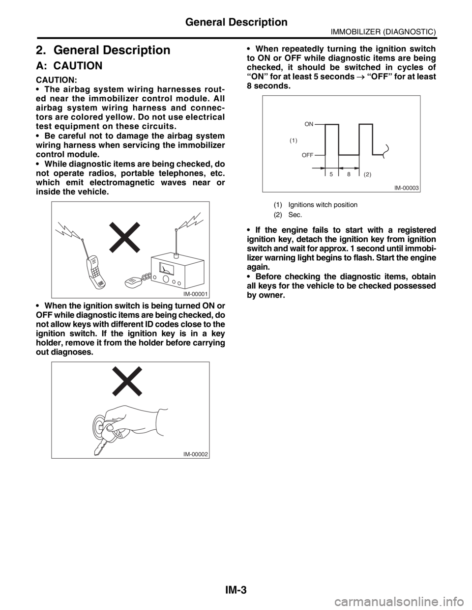
When the ignition switch is being turned ON or
OFF while diagnostic items are being checked, do
not allow keys with different ID codes close to the
ignition switch. If the ignition key is in a key
holder, remove it from the holder before carrying
out diagnoses. When repeatedly turning the ignition switch
to ON or OFF while diagnostic items are being
checked, it should be switched in cycles of
“ON” for at least 5 seconds → “OFF” for at least
8 seconds.
If the engine fails to start with a registered
ignition key, detach the ignition key from ignition
switch and wait for approx. 1 second until immobi-
lizer warning light begins to flash. Start the engine
again.
Before checking the diagnostic items, obtain
all keys for the vehicle to be checked possessed
by owner.
IM-00001
IM-00002
(1) Ignitions witch position
(2) Sec.
IM-00003
ON
OFF
58
(2) (1)
Page 649 of 2870

IM-7
IMMOBILIZER (DIAGNOSTIC)
Subaru Select Monitor
5. Subaru Select Monitor
A: OPERATION
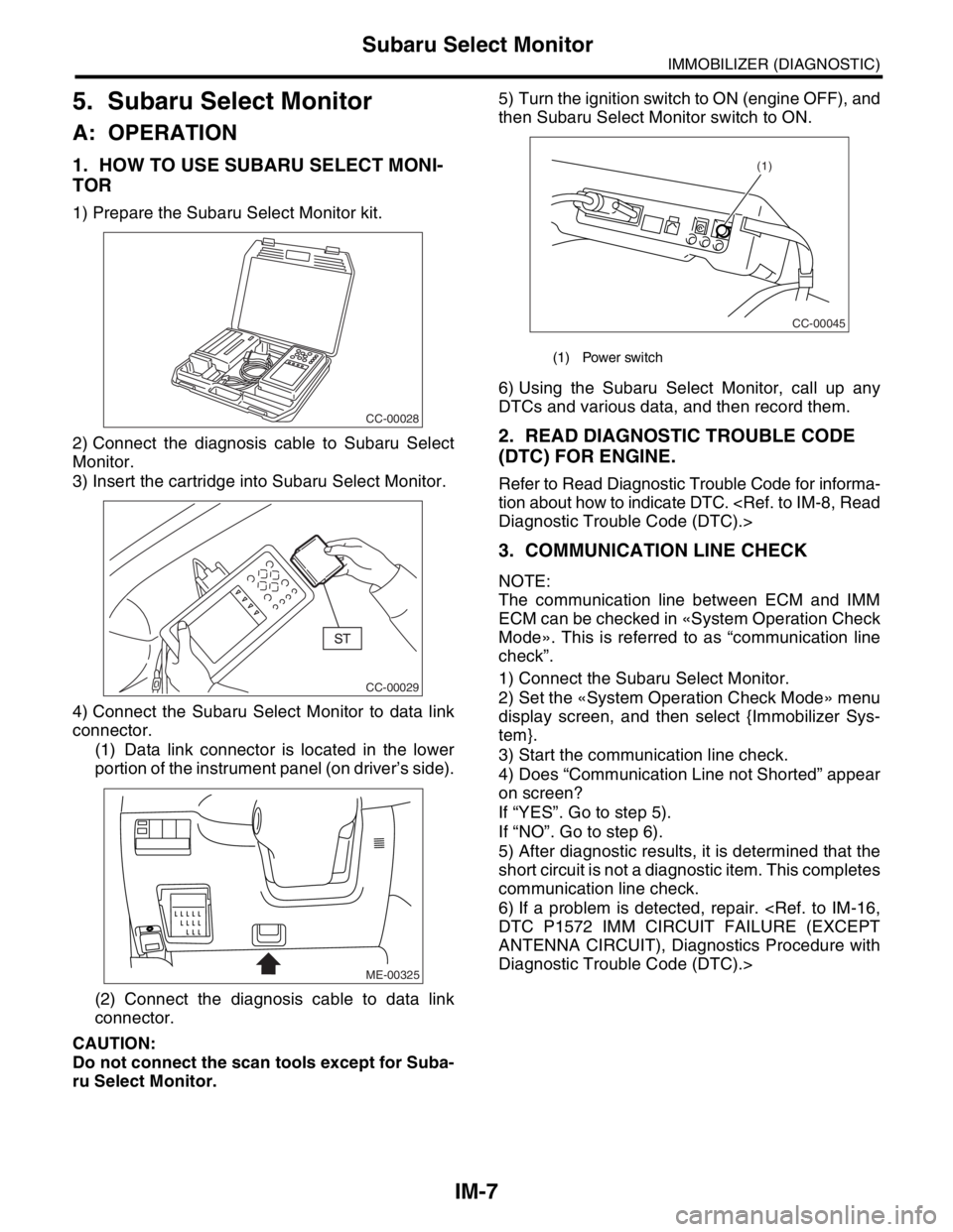
1. HOW TO USE SUBARU SELECT MONI-
TOR
1) Prepare the Subaru Select Monitor kit.
2) Connect the diagnosis cable to Subaru Select
Monitor.
3) Insert the cartridge into Subaru Select Monitor.
4) Connect the Subaru Select Monitor to data link
connector.
(1) Data link connector is located in the lower
portion of the instrument panel (on driver’s side).
(2) Connect the diagnosis cable to data link
connector.
CAUTION:
Do not connect the scan tools except for Suba-
ru Select Monitor.5) Turn the ignition switch to ON (engine OFF), and
then Subaru Select Monitor switch to ON.
6) Using the Subaru Select Monitor, call up any
DTCs and various data, and then record them.
2. READ DIAGNOSTIC TROUBLE CODE
(DTC) FOR ENGINE.
Refer to Read Diagnostic Trouble Code for informa-
tion about how to indicate DTC.
3. COMMUNICATION LINE CHECK
NOTE:
The communication line between ECM and IMM
ECM can be checked in «System Operation Check
Mode». This is referred to as “communication line
check”.
1) Connect the Subaru Select Monitor.
2) Set the «System Operation Check Mode» menu
display screen, and then select {Immobilizer Sys-
tem}.
3) Start the communication line check.
4) Does “Communication Line not Shorted” appear
on screen?
If “YES”. Go to step 5).
If “NO”. Go to step 6).
5) After diagnostic results, it is determined that the
short circuit is not a diagnostic item. This completes
communication line check.
6) If a problem is detected, repair.
ANTENNA CIRCUIT), Diagnostics Procedure with
Diagnostic Trouble Code (DTC).>
CC-00028
CC-00029
ME-00325
(1) Power switch
CC-00045
(1)