2004 SUBARU FORESTER radiator
[x] Cancel search: radiatorPage 372 of 2870
BS-6
BODY STRUCTURE
Datum Points
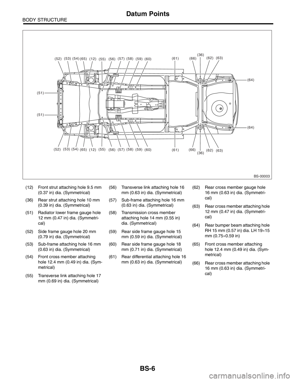
(12) Front strut attaching hole 9.5 mm
(0.37 in) dia. (Symmetrical)(56) Transverse link attaching hole 16
mm (0.63 in) dia. (Symmetrical)(62) Rear cross member gauge hole
16 mm (0.63 in) dia. (Symmetri-
cal)
(36) Rear strut attaching hole 10 mm
(0.39 in) dia. (Symmetrical)(57) Sub-frame attaching hole 16 mm
(0.63 in) dia. (Symmetrical)
(63) Rear cross member attaching hole
12 mm (0.47 in) dia. (Symmetri-
cal) (51) Radiator lower frame gauge hole
12 mm (0.47 in) dia. (Symmetri-
cal)(58) Transmission cross member
attaching hole 14 mm (0.55 in)
dia. (Symmetrical)
(64) Rear bumper beam attaching hole
RH 15 mm (0.57 in) dia. LH 19×15
mm (0.75×0.59 in) (52) Side frame gauge hole 20 mm
(0.79 in) dia. (Symmetrical)(59) Rear side frame gauge hole 15
mm (0.59 in) dia. (Symmetrical)
(53) Sub-frame attaching hole 16 mm
(0.63 in) dia. (Symmetrical)(60) Rear side frame gauge hole 18
mm (0.71 in) dia. (Symmetrical)(65) Front cross member attaching
hole 12.4 mm (0.49 in) dia. (Sym-
metrical)
(54) Front cross member attaching
hole 12.4 mm (0.49 in) dia. (Sym-
metrical)(61) Rear differential attaching hole 16
mm (0.63 in) dia. (Symmetrical)
(66) Rear cross member attaching hole
16 mm (0.63 in) dia. (Symmetri-
cal)
(55) Transverse link attaching hole 17
mm (0.69 in) dia. (Symmetrical)
BS-00003
(52)(53)(54)(65)(12)(55)(61)
(61)
(64)
(64)
(51)
(51)
(36)
(36)(66)
(66)(56)(57)(58)(59)(60)
(52)(53) (54)
(65)
(12)(55)
(56)(57)(58)
(59)
(60)(62)
(62)(63)
(63)
Page 401 of 2870
IDI-17
INSTRUMENTATION/DRIVER INFO
Ambient Sensor
8. Ambient Sensor
A: REMOVAL
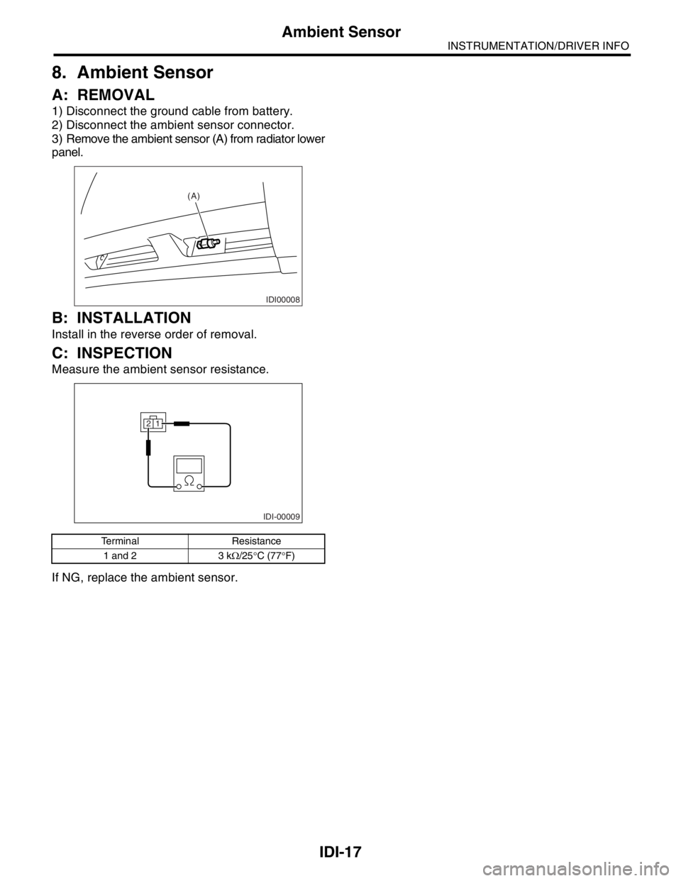
1) Disconnect the ground cable from battery.
2) Disconnect the ambient sensor connector.
3) Remove the ambient sensor (A) from radiator lower
panel.
B: INSTALLATION
Install in the reverse order of removal.
C: INSPECTION
Measure the ambient sensor resistance.
If NG, replace the ambient sensor.
Terminal Resistance
1 and 2 3 kΩ/25°C (77°F)
IDI00008
(A)
IDI-00009
21
Page 701 of 2870

PC-2
PRECAUTION
Precaution
1. Precaution
A: PRECAUTION
Please clearly understand and adhere to the follow-
ing general precautions. They must be strictly fol-
lowed to avoid minor or serious injury to the person
doing the work or people in the area.
1. ABS
Handle the ABS as a total system. Do not disas-
semble or attempt to repair individual parts. Doing
so could prevent the ABS system from operating
when needed or cause it to operate incorrectly and
result in injury.
2. BRAKE FLUID
If brake fluid gets in your eyes or on your skin, do
the following:
Wash out your eyes and seek immediate medical
attention.
Wash your skin with soap and then rinse thor-
oughly with water.
3. RADIATOR FAN
The radiator fan may rotate without warning, even
when the engine is not on. Do not place your hand,
cloth, tools, or other items near the fan at any time.
4. ROAD TESTS
Always conduct road tests in accordance with traf-
fic rules and regulations to avoid bodily injury and
interrupting traffic.
5. AIRBAG
To prevent bodily injury from unexpected deploy-
ment of airbags and unnecessary maintenance, fol-
low the instructions in this manual when performing
maintenance on airbag components or nearby, and
airbag wiring harnesses or nearby.
To prevent unexpected deployment, perform the
steps below and then wait at least 20 seconds to
discharge electricity before beginning work.
Step 1: Turn the ignition switch OFF.
Step 2: Disconnect the ground cable from bat-
tery.
6. AIRBAG DISPOSAL
To prevent bodily injury from unexpected airbag
deployment, do not dispose airbag modules in the
same way as other refuse. Follow all government
regulations concerning disposal of refuse.
7. AIRBAG MODULE
Adhere to the following when handling and storing
the airbag module to prevent bodily injury from un-
expected deployment:
Do not hold the harnesses or connectors to carry
module.
Do not face the bag in the direction that it opens
towards yourself or other people.
Do not face the bag in the direction that it opens
towards the floor or walls.
8. AIRBAG SPECIAL TOOLS
To prevent unexpected deployment, only use spe-
cial tools.
9. WINDOW
Always wear safety glasses when working around
any glass to prevent glass fragments from damag-
ing your eyes.
10.WINDOW ADHESIVE
Always use the recommended or alternative adhe-
sive when attaching glass to prevent it from coming
loose and falling, resulting in accidents and injury.
Page 750 of 2870
PM-13
PERIODIC MAINTENANCE SERVICE
Timing Belt
7. Timing Belt
A: REPLACEMENT
1. NON-TURBO MODEL
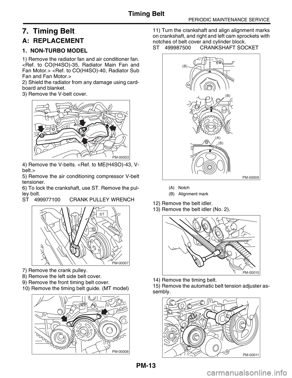
1) Remove the radiator fan and air conditioner fan.
2) Shield the radiator from any damage using card-
board and blanket.
3) Remove the V-belt cover.
4) Remove the V-belts.
5) Remove the air conditioning compressor V-belt
tensioner.
6) To lock the crankshaft, use ST. Remove the pul-
ley bolt.
ST 499977100 CRANK PULLEY WRENCH
7) Remove the crank pulley.
8) Remove the left side belt cover.
9) Remove the front timing belt cover.
10) Remove the timing belt guide. (MT model)11) Turn the crankshaft and align alignment marks
on crankshaft, and right and left cam sprockets with
notches of belt cover and cylinder block.
ST 499987500 CRANKSHAFT SOCKET
12) Remove the belt idler.
13) Remove the belt idler (No. 2).
14) Remove the timing belt.
15) Remove the automatic belt tension adjuster as-
sembly.
PM-00003
PM-00007
ST
PM-00008
(A) Notch
(B) Alignment mark
PM-00009
(B)
(B)
(B) (A)
PM-00010
PM-00011
Page 751 of 2870
PM-14
PERIODIC MAINTENANCE SERVICE
Timing Belt
16) Install in the reverse order of removal.
2. TURBO MODEL
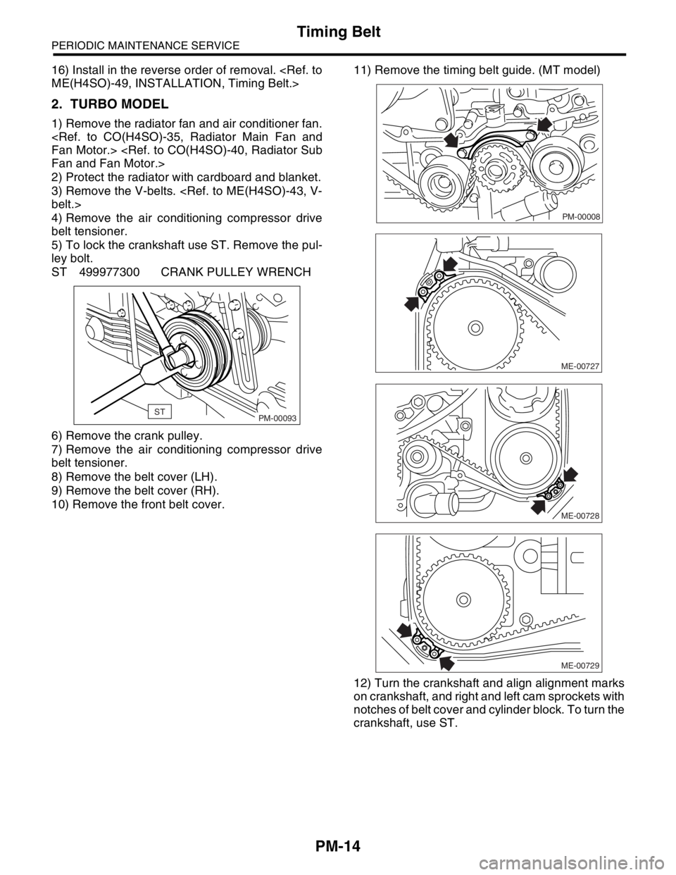
1) Remove the radiator fan and air conditioner fan.
2) Protect the radiator with cardboard and blanket.
3) Remove the V-belts.
4) Remove the air conditioning compressor drive
belt tensioner.
5) To lock the crankshaft use ST. Remove the pul-
ley bolt.
ST 499977300 CRANK PULLEY WRENCH
6) Remove the crank pulley.
7) Remove the air conditioning compressor drive
belt tensioner.
8) Remove the belt cover (LH).
9) Remove the belt cover (RH).
10) Remove the front belt cover.11) Remove the timing belt guide. (MT model)
12) Turn the crankshaft and align alignment marks
on crankshaft, and right and left cam sprockets with
notches of belt cover and cylinder block. To turn the
crankshaft, use ST.
STPM-00093
PM-00008
ME-00727
ME-00728
ME-00729
Page 757 of 2870
PM-20
PERIODIC MAINTENANCE SERVICE
Cooling System
11.Cooling System
A: INSPECTION
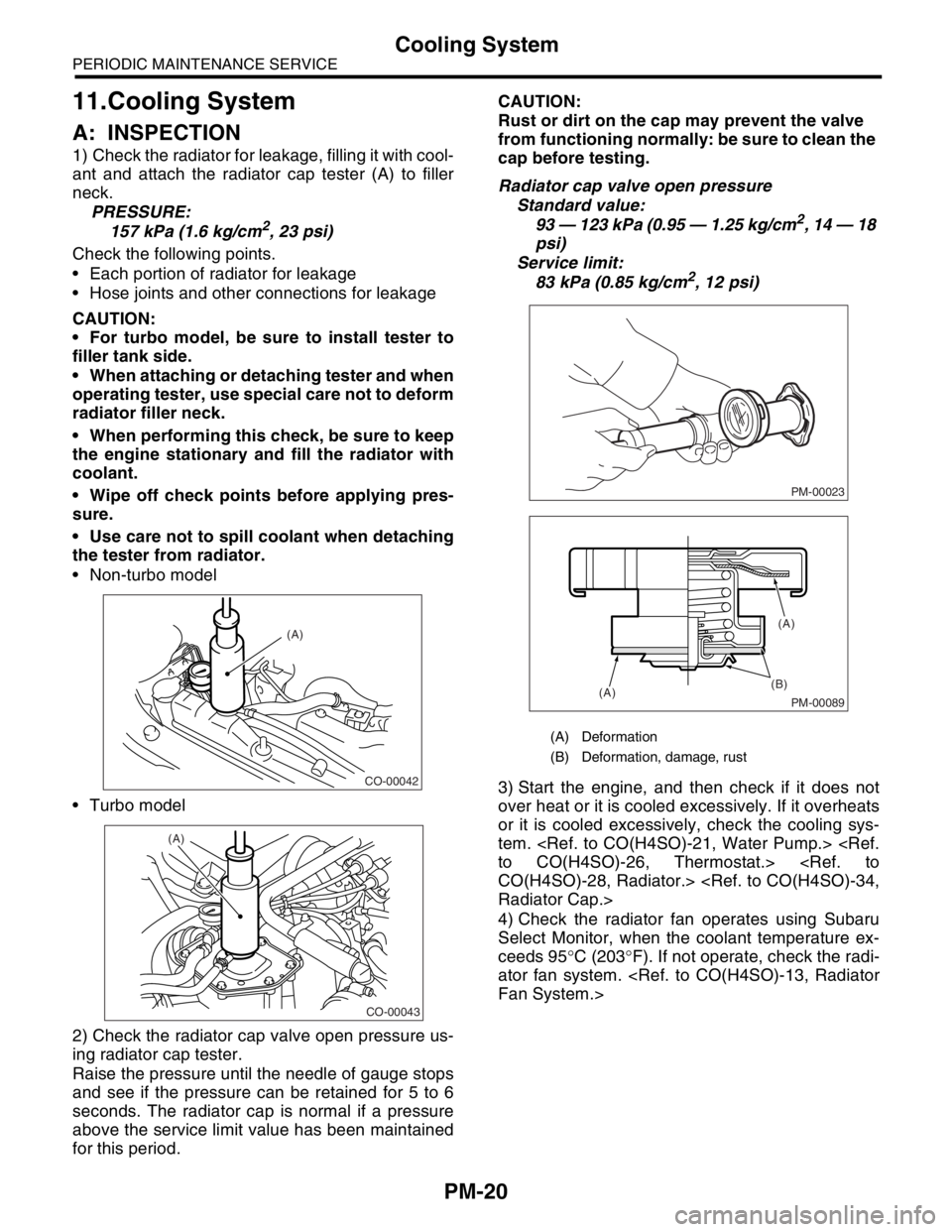
1) Check the radiator for leakage, filling it with cool-
ant and attach the radiator cap tester (A) to filler
neck.
PRESSURE:
157 kPa (1.6 kg/cm
2, 23 psi)
Check the following points.
Each portion of radiator for leakage
Hose joints and other connections for leakage
CAUTION:
For turbo model, be sure to install tester to
filler tank side.
When attaching or detaching tester and when
operating tester, use special care not to deform
radiator filler neck.
When performing this check, be sure to keep
the engine stationary and fill the radiator with
coolant.
Wipe off check points before applying pres-
sure.
Use care not to spill coolant when detaching
the tester from radiator.
Non-turbo model
Turbo model
2) Check the radiator cap valve open pressure us-
ing radiator cap tester.
Raise the pressure until the needle of gauge stops
and see if the pressure can be retained for 5 to 6
seconds. The radiator cap is normal if a pressure
above the service limit value has been maintained
for this period.CAUTION:
Rust or dirt on the cap may prevent the valve
from functioning normally: be sure to clean the
cap before testing.
Radiator cap valve open pressure
Standard value:
93 — 123 kPa (0.95 — 1.25 kg/cm2, 14 — 18
psi)
Service limit:
83 kPa (0.85 kg/cm
2, 12 psi)
3) Start the engine, and then check if it does not
over heat or it is cooled excessively. If it overheats
or it is cooled excessively, check the cooling sys-
tem.
4) Check the radiator fan operates using Subaru
Select Monitor, when the coolant temperature ex-
ceeds 95°C (203°F). If not operate, check the radi-
ator fan system.
CO-00042
(A)
CO-00043
(A)
(A) Deformation
(B) Deformation, damage, rust
PM-00023
PM-00089
(B)
(A)(A)
Page 758 of 2870
PM-21
PERIODIC MAINTENANCE SERVICE
Engine Coolant
12.Engine Coolant
A: REPLACEMENT
1. REPLACEMENT OF ENGINE COOLANT
WARNING:
The radiator is of the pressurized type. Do not
attempt to open the radiator cap immediately
after the engine has been stopped.
1) Lift-up the vehicle.
2) Remove the under cover.
3) Place a container under drain pipe.
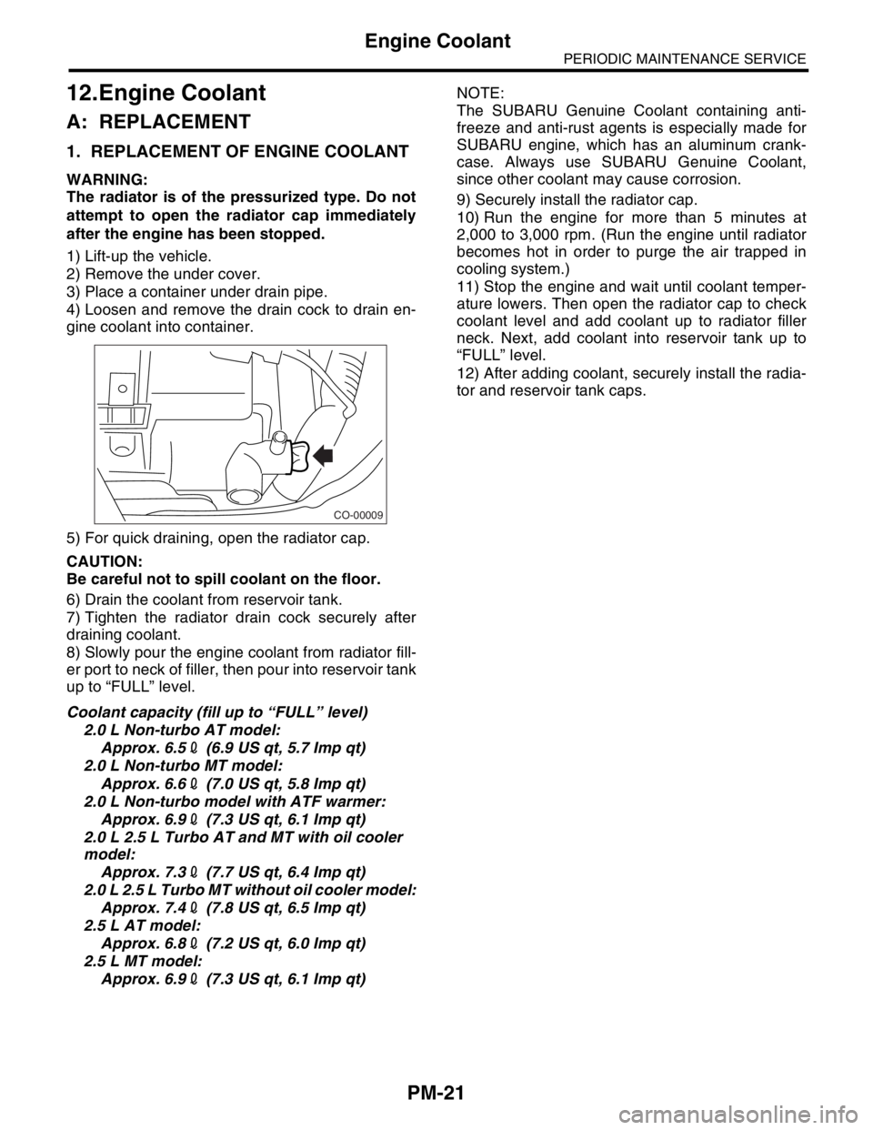
4) Loosen and remove the drain cock to drain en-
gine coolant into container.
5) For quick draining, open the radiator cap.
CAUTION:
Be careful not to spill coolant on the floor.
6) Drain the coolant from reservoir tank.
7) Tighten the radiator drain cock securely after
draining coolant.
8) Slowly pour the engine coolant from radiator fill-
er port to neck of filler, then pour into reservoir tank
up to “FULL” level.
Coolant capacity (fill up to “FULL” level)
2.0 L Non-turbo AT model:
Approx. 6.52 (6.9 US qt, 5.7 Imp qt)
2.0 L Non-turbo MT model:
Approx. 6.62 (7.0 US qt, 5.8 Imp qt)
2.0 L Non-turbo model with ATF warmer:
Approx. 6.92 (7.3 US qt, 6.1 Imp qt)
2.0 L 2.5 L Turbo AT and MT with oil cooler
model:
Approx. 7.32 (7.7 US qt, 6.4 Imp qt)
2.0 L 2.5 L Turbo MT without oil cooler model:
Approx. 7.42 (7.8 US qt, 6.5 Imp qt)
2.5 L AT model:
Approx. 6.82 (7.2 US qt, 6.0 Imp qt)
2.5 L MT model:
Approx. 6.92 (7.3 US qt, 6.1 Imp qt)NOTE:
The SUBARU Genuine Coolant containing anti-
freeze and anti-rust agents is especially made for
SUBARU engine, which has an aluminum crank-
case. Always use SUBARU Genuine Coolant,
since other coolant may cause corrosion.
9) Securely install the radiator cap.
10) Run the engine for more than 5 minutes at
2,000 to 3,000 rpm. (Run the engine until radiator
becomes hot in order to purge the air trapped in
cooling system.)
11) Stop the engine and wait until coolant temper-
ature lowers. Then open the radiator cap to check
coolant level and add coolant up to radiator filler
neck. Next, add coolant into reservoir tank up to
“FULL” level.
12) After adding coolant, securely install the radia-
tor and reservoir tank caps.
CO-00009
Page 895 of 2870
ME(H4SO)-26
MECHANICAL
Idle Speed
3. Idle Speed
A: INSPECTION
1) Before checking idle speed, check the following:
(1) Ensure the air cleaner element is free from
clogging, ignition timing is correct, spark plugs
are in good condition, and the hoses are con-
nected properly.
(2) Ensure the malfunction indicator light does
not illuminate.
2) Warm-up the engine.
3) Stop the engine, and then turn the ignition switch
to OFF.
4) When using the Subaru Select Monitor, refer to
the following.
tion.>
(1) Insert the cartridge to Subaru Select Moni-
tor.
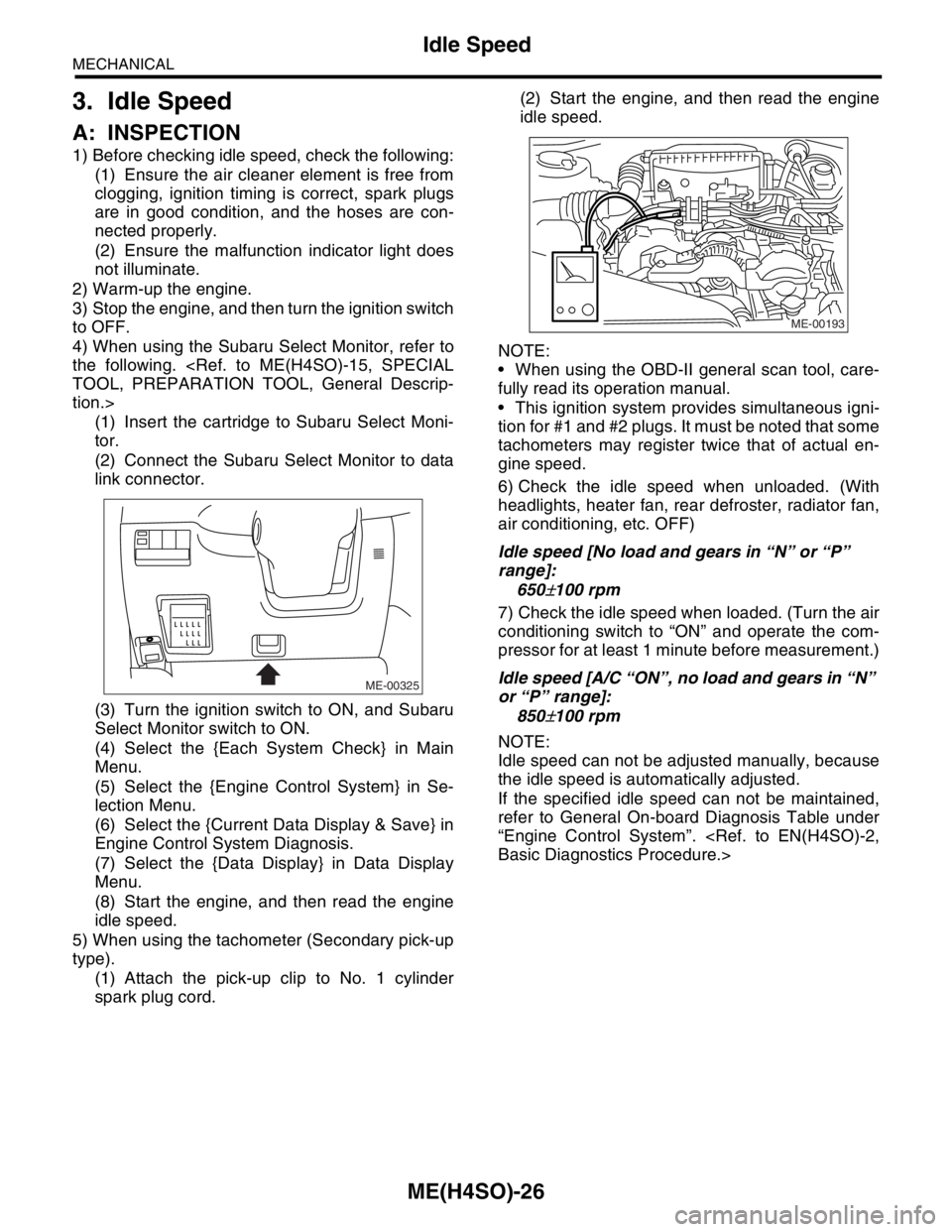
(2) Connect the Subaru Select Monitor to data
link connector.
(3) Turn the ignition switch to ON, and Subaru
Select Monitor switch to ON.
(4) Select the {Each System Check} in Main
Menu.
(5) Select the {Engine Control System} in Se-
lection Menu.
(6) Select the {Current Data Display & Save} in
Engine Control System Diagnosis.
(7) Select the {Data Display} in Data Display
Menu.
(8) Start the engine, and then read the engine
idle speed.
5) When using the tachometer (Secondary pick-up
type).
(1) Attach the pick-up clip to No. 1 cylinder
spark plug cord.(2) Start the engine, and then read the engine
idle speed.
NOTE:
When using the OBD-II general scan tool, care-
fully read its operation manual.
This ignition system provides simultaneous igni-
tion for #1 and #2 plugs. It must be noted that some
tachometers may register twice that of actual en-
gine speed.
6) Check the idle speed when unloaded. (With
headlights, heater fan, rear defroster, radiator fan,
air conditioning, etc. OFF)
Idle speed [No load and gears in “N” or “P”
range]:
650
±100 rpm
7) Check the idle speed when loaded. (Turn the air
conditioning switch to “ON” and operate the com-
pressor for at least 1 minute before measurement.)
Idle speed [A/C “ON”, no load and gears in “N”
or “P” range]:
850
±100 rpm
NOTE:
Idle speed can not be adjusted manually, because
the idle speed is automatically adjusted.
If the specified idle speed can not be maintained,
refer to General On-board Diagnosis Table under
“Engine Control System”.
ME-00325
ME-00193