Page 2200 of 2870
EN(H4DOTC 2.5)-176
ENGINE (DIAGNOSTIC)
Diagnostic Procedure with Diagnostic Trouble Code (DTC)
AV:DTC P0692 COOLING FAN 1 CONTROL CIRCUIT HIGH
DTC DETECTING CONDITION:
Two consecutive driving cycles with fault
TROUBLE SYMPTOM:
Radiator fan does not operate properly.
Over-heating
CAUTION:
After repair or replacement of faulty parts, conduct Clear Memory Mode
OPERATION, Clear Memory Mode.> and Inspection Mode
Inspection Mode.>.
Page 2202 of 2870

EN(H4DOTC 2.5)-178
ENGINE (DIAGNOSTIC)
Diagnostic Procedure with Diagnostic Trouble Code (DTC)
AW:DTC P0700 TRANSMISSION CONTROL SYSTEM (MIL REQUEST)
NOTE:
For the diagnostic procedure, refer to AT section.
Procedure.>
Step Check Yes No
1 CHECK OUTPUT SIGNAL FROM ECM.
1) Turn the ignition switch to OFF.
2) Connect the test mode connector.
3) Turn the ignition switch to ON.
4) While operating the radiator fan relay, mea-
sure voltage between ECM and chassis ground.
N
OTE:
Radiator fan relay operation can be executed
using Subaru Select Monitor. For procedure,
refer to “Compulsory Valve Operation Check
Mode”.
sory Valve Operation Check Mode.>
Connector & terminal
(B135) No. 24 (+) — Chassis ground (
−):
(B135) No. 25 (+) — Chassis ground (
−):Does the voltage vary between
0 — 10 V?Even if the mal-
function indicator
light illuminates,
the circuit has
returned to a nor-
mal condition at
this time. In this
case, repair poor
contact in ECM
connector.Go to step 2.
2 CHECK SHORT CIRCUIT IN RADIATOR FAN
RELAY CONTROL CIRCUIT.
1) Turn the ignition switch to OFF.
2) Remove the main fan relay, sub fan relay
and fan mode relay.
3) Disconnect the test mode connectors
4) Turn the ignition switch to ON.
5) Measure the voltage between ECM and
chassis ground.
Connector & terminal
(B135) No. 24 (+) — Chassis ground (
−):
(B135) No. 25 (+) — Chassis ground (
−):Is the voltage more than 10 V? Repair battery
short circuit in radi-
ator fan relay con-
trol circuit. After
repair, replace the
ECM.
FU(H4DOTC 2.5)-
41, Engine Con-
trol Module
(ECM).>Go to step 3.
3 CHECK FAN RELAY.
1) Turn the ignition switch to OFF.
2) Remove the fan relay.
3) Measure the resistance between fan relay
terminals.
Te r m i n a l s
No. 30 — No. 31 (Main fan relay)
No. 28 — No. 29 (Sub fan relay)Is the resistance less than 1
Ω?Replace the fan
relay and ECM.
FU(H4DOTC 2.5)-
41, Engine Con-
trol Module
(ECM).>Go to step 4.
4 CHECK FAN MODE RELAY.
1) Remove the fan mode relay.
2) Measure the resistance between fan mode
relay terminals.
Te r m i n a l s
No. 8 — No. 9: (Fan mode relay)Is the resistance less than 1
Ω?Replace the fan
mode relay and
ECM.
FU(H4DOTC 2.5)-
41, Engine Con-
trol Module
(ECM).>Go to step 5.
5 CHECK POOR CONTACT.
Check poor contact in ECM connector.Is there poor contact in ECM
connector?Repair the poor
contact in ECM
connector.Replace the ECM.
FU(H4DOTC 2.5)-
41, Engine Con-
trol Module
(ECM).>
Page 2315 of 2870

4AT-3
AUTOMATIC TRANSMISSION
General Description
6. SELECTOR POSITION
7. HYDRAULIC CONTROL AND LUBRICA-
TION
8. COOLING AND HARNESS9. TRANSFER
P (Park)Transmission in neutral, output member immov-
able, and engine start possible
R
(Reverse)Transmission in reverse
N (Neu-
tral)Transmission in neutral and engine start possi-
ble
D (Drive)Automatic gear change 1st
←
→ 2nd ←
→ 3rd ←
→
4th
3 (3rd)Automatic gear change 1st
←
→ 2nd ←
→ 3rd ←
4th
2 (2nd)Automatic gear change 1st
←
→ 2nd ← 3rd ←
4th
1 (1st)1st gear locked (Deceleration possible 1st ←
2nd ← 3rd ← 4th)
Control
methodWire cable type
Ty p eElectronic/hydraulic control
[Four forward speed
changes by electrical signals
of vehicle speed and accel-
erator (throttle) opening]
FluidDEXRON III type automatic
transmission fluid
Fluid capac-
ity2.0 L Non-
turbo model8.4 — 8.72 (8.9 — 9.2 US
qt, 7.4 — 7.7 Imp qt)
Except for
2.0 L Non-
turbo model9.3 — 9.62 (9.8 — 10.1 US
qt, 8.2 — 8.4 Imp qt)
Lubrication systemForced feed lubrication with
oil pump
OilAutomatic transmission fluid
(above mentioned)
Cooling SystemLiquid-cooled cooler incorpo-
rated in radiator
Inhibitor switch 12 poles
Transmission harness 20 poles
Model2.0 L Non-
turbo2.5 L Non-
turboTu r b o
Transfer
typeMulti-plate transfer (MPT)
Drive &
driven plate
number of
transfer
clutch456
Control
methodElectronic, hydraulic type
LubricantThe same Automatic transmission fluid used
in automatic transmission
Reduction
gear ratio1.000 (53/53)
Page 2392 of 2870

4AT-79
AUTOMATIC TRANSMISSION
ATF Cooler Pipe and Hose
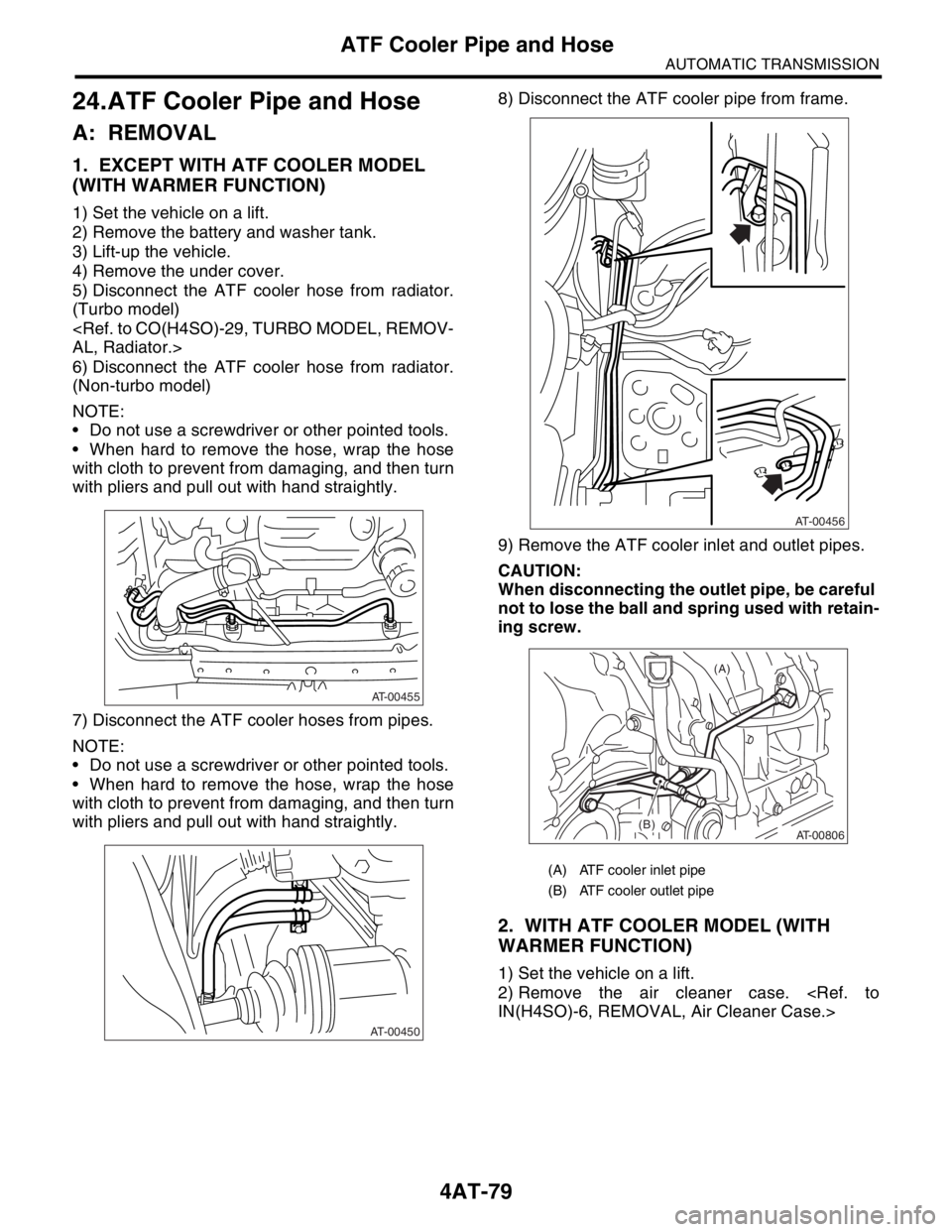
24.ATF Cooler Pipe and Hose
A: REMOVAL
1. EXCEPT WITH ATF COOLER MODEL
(WITH WARMER FUNCTION)
1) Set the vehicle on a lift.
2) Remove the battery and washer tank.
3) Lift-up the vehicle.
4) Remove the under cover.
5) Disconnect the ATF cooler hose from radiator.
(Turbo model)
AL, Radiator.>
6) Disconnect the ATF cooler hose from radiator.
(Non-turbo model)
NOTE:
Do not use a screwdriver or other pointed tools.
When hard to remove the hose, wrap the hose
with cloth to prevent from damaging, and then turn
with pliers and pull out with hand straightly.
7) Disconnect the ATF cooler hoses from pipes.
NOTE:
Do not use a screwdriver or other pointed tools.
When hard to remove the hose, wrap the hose
with cloth to prevent from damaging, and then turn
with pliers and pull out with hand straightly.8) Disconnect the ATF cooler pipe from frame.
9) Remove the ATF cooler inlet and outlet pipes.
CAUTION:
When disconnecting the outlet pipe, be careful
not to lose the ball and spring used with retain-
ing screw.
2. WITH ATF COOLER MODEL (WITH
WARMER FUNCTION)
1) Set the vehicle on a lift.
2) Remove the air cleaner case.
IN(H4SO)-6, REMOVAL, Air Cleaner Case.>
AT-00455
AT-00450
(A) ATF cooler inlet pipe
(B) ATF cooler outlet pipe
AT-00456
AT-00806
(A)
(B)
Page 2394 of 2870

4AT-81
AUTOMATIC TRANSMISSION
ATF Cooler Pipe and Hose
B: INSTALLATION
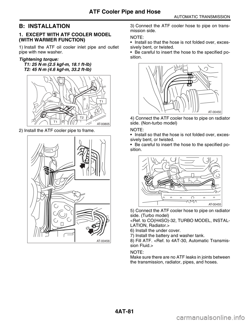
1. EXCEPT WITH ATF COOLER MODEL
(WITH WARMER FUNCTION)
1) Install the ATF oil cooler inlet pipe and outlet
pipe with new washer.
Tightening torque:
T1: 25 N
⋅m (2.5 kgf-m, 18.1 ft-lb)
T2: 45 N
⋅m (4.6 kgf-m, 33.2 ft-lb)
2) Install the ATF cooler pipe to frame.3) Connect the ATF cooler hose to pipe on trans-
mission side.
NOTE:
Install so that the hose is not folded over, exces-
sively bent, or twisted.
Be careful to insert the hose to the specified po-
sition.
4) Connect the ATF cooler hose to pipe on radiator
side. (Non-turbo model)
NOTE:
Install so that the hose is not folded over, exces-
sively bent, or twisted.
Be careful to insert the hose to the specified po-
sition.
5) Connect the ATF cooler hose to pipe on radiator
side. (Turbo model)
LATION, Radiator.>
6) Install the under cover.
7) Install the battery and washer tank.
8) Fill ATF.
sion Fluid.>
NOTE:
Make sure there are no ATF leaks in joints between
the transmission, radiator, pipes, and hoses.
AT-00805
T1
T1
T2
AT-00456
AT-00450
AT-00455
Page 2396 of 2870
4AT-83
AUTOMATIC TRANSMISSION
ATF Cooler Pipe and Hose
C: INSPECTION
Repair or replace any defective hoses, pipes,
clamps, and washers found from the inspection be-
low.
1) Check for ATF leaks in joints between the trans-
mission, radiator, pipes, and hoses.
2) Check for deformed clamps.
3) Lightly bend the hose and check for cracks in the
surface and other damage.
4) Pinch the hose with your fingers and check for
poor elasticity. Also check for poor elasticity in the
parts where the clamp was installed by pressing
with your fingernail.
5) Check for peeling, cracks, and deformation at
the tip of the hose.