2004 SUBARU FORESTER radiator
[x] Cancel search: radiatorPage 1303 of 2870

EN(H4SO)-205
ENGINE (DIAGNOSTIC)
Diagnostic Procedure with Diagnostic Trouble Code (DTC)
Step Check Yes No
1 CHECK OUTPUT SIGNAL FROM ECM.
1) Turn the ignition switch to OFF.
2) Connect the test mode connector at the
lower portion of instrument panel (on the
driver’s side).
3) Turn the ignition switch to ON.
4) While operating the radiator fan relay, mea-
sure the voltage between ECM and chassis
ground.
N
OTE:
Radiator fan relay operation can be executed
using Subaru Select Monitor. For procedure,
refer to “Compulsory Valve Operation Check
Mode”.
Connector & terminal
(B134) No. 14 (+) — Chassis ground (
−):
(B134) No. 13 (+) — Chassis ground (
−):Is the voltage 0 — 10 V? Even if the mal-
function indicator
light illuminates,
the circuit has
returned to a nor-
mal condition at
this time. In this
case, repair poor
contact in ECM
connector.Go to step 2.
2 CHECK SHORT CIRCUIT IN RADIATOR FAN
RELAY CONTROL CIRCUIT.
1) Turn the ignition switch to OFF.
2) Remove the main fan relay and sub fan
relay. (model with A/C)
3) Disconnect the test mode connectors
4) Turn the ignition switch to ON.
5) Measure the voltage between ECM and
chassis ground.
Connector & terminal
(B134) No. 14 (+) — Chassis ground (
−):
(B134) No. 13 (+) — Chassis ground (
−):Is the voltage more than 10 V? Repair battery
short circuit in
radiator fan relay
control circuit.
After repair,
replace the ECM.
Engine Control
Module (ECM).>Go to step 3.
3 CHECK MAIN FAN RELAY.
1) Turn the ignition switch to OFF.
2) Remove the main fan relay.
3) Measure the resistance between main fan
relay terminals.
Te r m i n a l s
No. 30 — No. 31:Is the resistance less than 1
Ω?Replace the main
fan relay and
ECM.
Engine Control
Module (ECM).>Go to step 4.
4 CHECK SUB FAN RELAY.
1) Remove the sub fan relay.
2) Measure the resistance between sub fan
relay terminals.
Te r m i n a l s
No. 28 — No. 29:Is the resistance less than 1
Ω?Replace the sub
fan relay and
ECM.
Engine Control
Module (ECM).>Go to step 5.
5 CHECK POOR CONTACT.
Check poor contact in ECM connector.Is there poor contact in ECM
connector?Repair the poor
contact in ECM
connector.Replace the ECM.
Engine Control
Module (ECM).>
Page 1488 of 2870

ME(H4DOTC)-32
MECHANICAL
Idle Speed
3. Idle Speed
A: INSPECTION
1. USING SUBARU SELECT MONITOR
1) Before checking the idle speed, check the fol-
lowing:
(1) Ensure the air cleaner element is free from
clogging, ignition timing is correct, spark plugs
are in good condition, and that the hoses are
connected properly.
(2) Ensure the malfunction indicator light does
not illuminate.
2) Warm-up the engine.
3) Stop the engine, and then turn the ignition switch
to OFF.
4) Insert the cartridge to Subaru Select Monitor.
5) Connect the Subaru Select Monitor to data link
connector.
6) Turn the ignition switch to ON, and Subaru Se-
lect Monitor switch to ON.
7) Select the {2. Each System Check} in Main
Menu.
8) Select the {Engine Control System} in Selection
Menu.
9) Select the {1. Current Data Display & Save} in
Engine Control System Diagnosis.
10) Select the {1.12 Data Display} in Data Display
Menu.
11) Start the engine, and then read the engine idle
speed.
12) Check the idle speed when unloaded. (With
headlights, heater fan, rear defroster, radiator fan,
air conditioning, etc. OFF)
Idle speed [No load and gears in neutral]:
700
±100 rpm
13) Check the idle speed when loaded. (Turn the
air conditioning switch to “ON” and operate the
compressor for at least 1 minute before measure-
ment.)
Idle speed [A/C “ON”, no load and gears in neu-
tral]:
A/C Refrigerant pressure (LOW)
MT: 725
±100 rpm
AT: 750
±100 rpm
A/C Refrigerant pressure (HIGH)
MT: 800
±100 rpm
AT: 825
±100 rpm
NOTE:
As idle speed is controlled by the automatic adjust-
ment type, it can not be adjusted manually. If the
idle speed is out of specifications, refer to General
On-board Diagnosis Table under “Engine Control
System”.
Page 1499 of 2870

ME(H4DOTC)-41
MECHANICAL
Engine Assembly
9. Engine Assembly
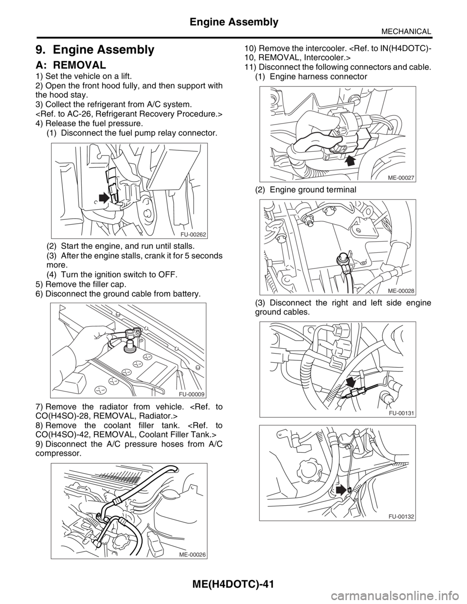
A: REMOVAL
1) Set the vehicle on a lift.
2) Open the front hood fully, and then support with
the hood stay.
3) Collect the refrigerant from A/C system.
4) Release the fuel pressure.
(1) Disconnect the fuel pump relay connector.
(2) Start the engine, and run until stalls.
(3) After the engine stalls, crank it for 5 seconds
more.
(4) Turn the ignition switch to OFF.
5) Remove the filler cap.
6) Disconnect the ground cable from battery.
7) Remove the radiator from vehicle.
8) Remove the coolant filler tank.
9) Disconnect the A/C pressure hoses from A/C
compressor.10) Remove the intercooler.
11) Disconnect the following connectors and cable.
(1) Engine harness connector
(2) Engine ground terminal
(3) Disconnect the right and left side engine
ground cables.
FU-00262
FU-00009
ME-00026
ME-00027
ME-00028
FU-00131
FU-00132
Page 1507 of 2870

ME(H4DOTC)-49
MECHANICAL
Engine Assembly
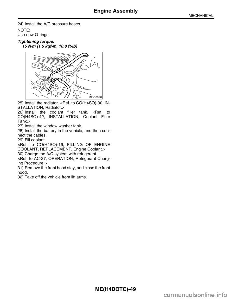
24) Install the A/C pressure hoses.
NOTE:
Use new O-rings.
Tightening torque:
15 N
⋅m (1.5 kgf-m, 10.8 ft-lb)
25) Install the radiator.
26) Install the coolant filler tank.
Tank.>
27) Install the window washer tank.
28) Install the battery in the vehicle, and then con-
nect the cables.
29) Fill coolant.
30) Charge the A/C system with refrigerant.
31) Remove the front hood stay, and close the front
hood.
32) Take off the vehicle from lift arms.
ME-00026
Page 1634 of 2870

EN(H4DOTC)-4
ENGINE (DIAGNOSTIC)
Check List for Interview
2. Check List for Interview
A: INSPECTION
1. CHECK LIST NO. 1
Check the following items when problem has occurred.
NOTE:
Use copies of this page for interviewing customers.
Customer’s name Engine No.
Date of sale Fuel brand
Date of repair
Odometer readingkm
V.I.N.miles
Weather❏ Fine
❏ Cloudy
❏ Rainy
❏ Snowy
❏ Va r i o u s / O t h e r s :
Ambient air temperature°C (°F)
❏ Hot
❏ War m
❏ Cool
❏ Cold
Place❏ Highway
❏ Suburbs
❏ Inner city
❏ Uphill
❏ Downhill
❏ Rough road
❏ Others:
Engine temperature❏ Cold
❏ War ming-up
❏ After warming-up
❏ Any temperature
❏ Others:
Engine speed rpm
Vehicle speed km/h (MPH)
Driving conditions❏ Not affected
❏ At starting
❏ While idling
❏ At racing
❏ While accelerating
❏ While cruising
❏ While decelerating
❏ While turning (RH/LH)
Headlight❏ ON / ❏ OFF Rear defogger❏ ON / ❏ OFF
Blower❏ ON / ❏ OFF Radio❏ ON / ❏ OFF
A/C compressor❏ ON / ❏ OFF CD/Cassette❏ ON / ❏ OFF
Radiator fan❏ ON / ❏ OFF Car phone❏ ON / ❏ OFF
Fr o nt wi pe r❏ ON / ❏ OFF CB❏ ON / ❏ OFF
Rear Wiper❏ ON / ❏ OFF
Page 1648 of 2870

EN(H4DOTC)-18
ENGINE (DIAGNOSTIC)
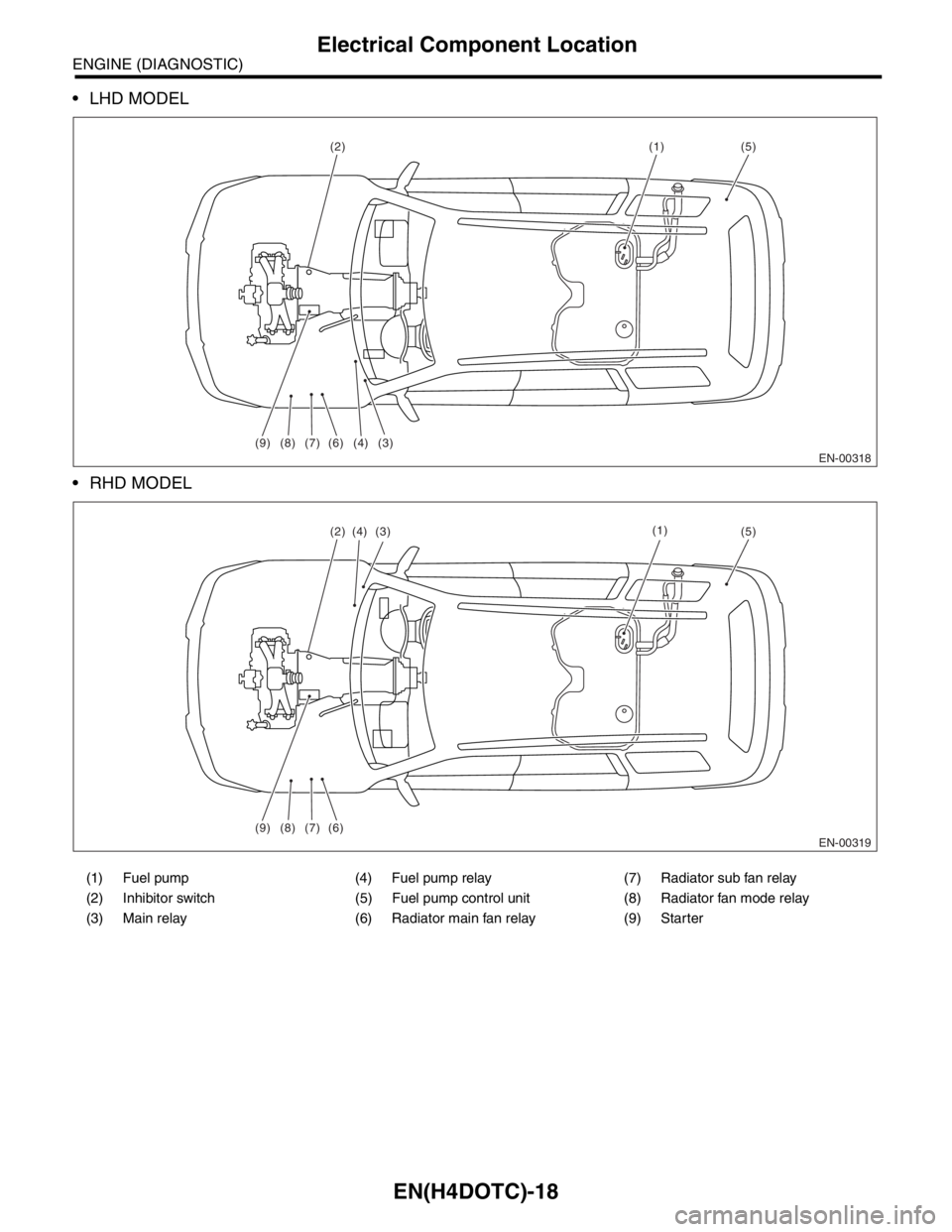
Electrical Component Location
LHD MODEL
RHD MODEL
(1) Fuel pump (4) Fuel pump relay (7) Radiator sub fan relay
(2) Inhibitor switch (5) Fuel pump control unit (8) Radiator fan mode relay
(3) Main relay (6) Radiator main fan relay (9) Starter
EN-00318
(1)
(9)
(2)
(3) (4) (7) (8) (6)
(5)
EN-00319
(1)
(9) (7)(8) (6)
(2)(5)(3)(4)
Page 1655 of 2870

EN(H4DOTC)-25
ENGINE (DIAGNOSTIC)
Engine Control Module (ECM) I/O Signal
Sensor power supply B136 16 5 5 —
Oil flow
control
solenoid
valve RHSignal (+) B134 18ON: 10 — 13
OFF: 0ON: 13 — 14
OFF: 0—
Signal (−) B134 28 0 0 —
Oil flow
control
solenoid
valve LHSignal (+) B134 19ON: 10 — 13
OFF: 0ON: 13 — 14
OFF: 0—
Signal (−) B134 29 0 0 —
Ignition
control#1 B135 18 0 13 — 14 Waveform
#2 B135 17 0 13 — 14 Waveform
#3 B135 16 0 13 — 14 Waveform
#4 B135 15 0 13 — 14 Waveform
Fuel injec-
tor#1 B136 6 10 — 13 1 — 14 Waveform
#2 B136 5 10 — 13 1 — 14 Waveform
#3 B136 4 10 — 13 1 — 14 Waveform
#4 B136 3 10 — 13 1 — 14 Waveform
Idle air
control
solenoid
valveSignal B134 27 0 or 13 — 14 0 or 13 — 14 Waveform
Fuel pump
control unitDiagnosis
signalB137 28 10 — 13 13 — 14 Waveform
Control
signalB135 27 0 or 5 0 or 5 —
A/C relay control B135 33ON: 0.5, or less
OFF: 10 — 13ON: 0.5, or less
OFF: 13 — 14—
Radiator fan relay 1 con-
trolB135 25ON: 0.5, or less
OFF: 10 — 13ON: 0.5, or less
OFF: 13 — 14—
Radiator fan relay 2 con-
trolB135 24ON: 0.5, or less
OFF: 10 — 13ON: 0.5, or less
OFF: 13 — 14Model with A/C
Malfunction indicator
lightB134 17 — —Light “ON”: 1, or less
Light “OFF”: 10 — 14
Engine speed output B134 23 — 0 — 13, or more Waveform
Purge control solenoid
valveB134 14ON: 1, or less
OFF: 10 — 13ON: 1, or less
OFF: 13 — 14Wavefor m
Manifold
absolute
pressure
sensorSignal B136 22 1.7 — 2.4 1.1 — 1.6
— Pow er
supplyB136 16 5 5
GND
(sensors)B136 35 0 0
Fuel level sensor B136 20 0.12 — 4.75 0.12 — 4.75 —
Small light switch B137 12ON: 0
OFF: 10 — 13ON: 0
OFF: 13 — 14—
Blower fan switch B137 13ON: 0
OFF: 10 — 13ON: 0
OFF: 13 — 14—
Rear defogger switch B137 11ON: 0
OFF: 10 — 13ON: 0
OFF: 13 — 14—
Power steering oil pres-
sure switchB137 10 10 — 13ON: 0
OFF: 13 — 14—
Wiper switch B137 23ON: 10 — 13
OFF: 0ON: 13 — 14
OFF: 0— DESCRIPTION Connector No. Terminal No.Signal (V)
NOTE
Ignition SW ON
(engine OFF)Engine ON
(Idling)
Page 1665 of 2870

EN(H4DOTC)-35
ENGINE (DIAGNOSTIC)
Subaru Select Monitor
NOTE:
For detailed operation procedure, refer to the “SUBARU SELECT MONITOR OPERATION MANUAL”.
5. READ CURRENT DATA FOR ENGINE (OBD MODE)
1) On the «Main Menu» display screen, select the {Each System Check} and press the [YES] key.
2) On the «System Selection Menu» display screen, select the {Engine} and press the [YES] key.
3) Press the [YES] key after the information of engine type was displayed.
4) On the «Engine Diagnosis» display screen, select the {OBD System} and press the [YES] key.
5) On the «OBD Menu» screen, select the {Current Data Display/Save}, and then press the [YES] key.
6) On the «Data Display Menu» screen, select the {Data Display} and press the [YES] key.
7) Using the scroll key, move the display screen up or down until the desired data is shown.
A list of the support data is shown in the following table.
Air conditioning signal A/C Compressor Signal ON or OFF
Radiator main fan relay signal Radiator Fan Relay #1 ON or OFF
Knocking signal Knocking Signal ON or OFF
Radiator sub fan relay signal Radiator Fan Relay #2 ON or OFF
Power steering switch signal P/S Switch ON or OFF
Engine torque control permission signal Torque Permission Signal ON or OFF
Rear oxygen sensor rich signal Rear Oxygen Rich Signal ON or OFF
Starter switch signal Starter Switch ON or OFF
Idle switch signal Idle Switch ON or OFF
Crankshaft position sensor signal Crankshaft Position Sig. ON or OFF
Camshaft position sensor signal Camshaft Position Sig. ON or OFF
Rear defogger switch signal Rear Defogger SW ON or OFF
Blower fan switch signal Blower Fan SW ON or OFF
Small light switch signal Light Switch ON or OFF
Tumble generated valve output signal TGV Output ON or OFF
Exhaust temperature signal Exhaust Gas Temperature°C
Estimated cumulative driving distance Odd Meter km
Roughness Monitor for #1 cylinder Roughness Monitor #1 —
Roughness Monitor for #2 cylinder Roughness Monitor #2 —
Roughness Monitor for #3 cylinder Roughness Monitor #3 —
Roughness Monitor for #4 cylinder Roughness Monitor #4 —
Wiper switch signal Wiper Switch ON or OFF
A/C middle pressure switch signal A/C Mid pressure switch ON or OFF
AT retard angle demand signal Retard Signal from AT ON or OFF
AT fuel cut demand signal Fuel Cut Signal from AT ON or OFF
Description Display Unit of measure
Number of diagnosis code Number of Diag. Code —
Condition of malfunction indicator light MI (MIL) ON or OFF
Monitoring test of misfire Misfire monitoring Complete or incomplete
Monitoring test of fuel system Fuel system monitoring Complete or incomplete
Monitoring test of comprehensive component Component monitoring Complete or incomplete
Test of catalyst Catalyst Diagnosis Complete or incomplete
Test of heating-type catalyst Heated catalyst No support
Test of evaporative emission purge control system Evaporative purge system No support
Test of secondary air system Secondary air system No support
Test of air conditioning system refrigerant A/C system refrigerant No support
Test of oxygen sensor Oxygen sensor Complete or incomplete
Test of oxygen sensor heater Oxygen Heater Diagnosis Complete or incomplete
Test of EGR system EGR system No supportRemarks Display Unit of measure