2004 SUBARU FORESTER radiator
[x] Cancel search: radiatorPage 997 of 2870

CO(H4SO)-14
COOLING
Radiator Fan System
B: INSPECTION
DETECTING CONDITION:
Engine coolant temperature is above 95°C (203°F).
Vehicle speed is below 19 km/h (12 MPH).
TROUBLE SYMPTOM:
Radiator main fan and sub fan does not rotate under the above conditions.
Step Check Yes No
1 CHECK OPERATION OF RADIATOR FAN.
1) Connect the test mode connector.
2) Turn the ignition switch to ON.
3) Using Subaru Select Monitor, check the
compulsory operation of radiator fan relay.
N
OTE:
With Subaru Select Monitor
When checking the compulsory operation of
radiator fan, the radiator main and sub fan
repeat the rotation in order of following: low
speed rotation → high speed rotation → off.
Subaru Select Monitor
Refer to Compulsory Valve Operation Check
Mode for detail procedures.
Check Mode.>Do the radiator main and sub
fan rotate at low speed?Go to step 2.Go to step 3.
2 CHECK OPERATION OF RADIATOR FAN.
1) Connect the test mode connector.
2) Turn the ignition switch to ON.
3) Using Subaru Select Monitor, check the
compulsory operation of radiator fan relay.
N
OTE:
With Subaru Select Monitor
When checking the compulsory operation of
radiator fan, the radiator main and sub fan
repeat the rotation in order of following: low
speed rotation → high speed rotation → off.
Subaru Select Monitor
Refer to Compulsory Valve Operation Check
Mode for detail procedures.
Check Mode.>Do the radiator main and sub
fan rotate at high speed?Radiator main fan
system is okay.Go to step 32.
3 CHECK POWER SUPPLY TO MAIN FAN RE-
LAY.
1) Turn the ignition switch to OFF.
2) Remove the fan relay 1 from A/C relay
holder.
3) Measure the voltage between main fan
relay terminal and chassis ground.
Connector & terminal
(F27) No. 31 (+) — Chassis ground (
−):Is the voltage more than 10 V? Go to step 4.Go to step 5.
4 CHECK POWER SUPPLY TO MAIN FAN RE-
LAY.
1) Turn the ignition switch to ON.
2) Measure the voltage between main fan
relay terminal and chassis ground.
Connector & terminal
(F27) No. 34 (+) — Chassis ground (
−):Is the voltage more than 10 V? Go to step 8.Go to step 7.
5 CHECK FUSE.
1) Remove the fuse from A/C relay holder.
2) Check the condition of fuse.Is the fuse blown out? Replace the fuse. Go to step 6.
Page 998 of 2870

CO(H4SO)-15
COOLING
Radiator Fan System
6 CHECK HARNESS OF FUSE TERMINAL
AND MAIN FAN RELAY TERMINAL.
1) Turn the ignition switch to OFF.
2) Measure the resistance between 20 A fuse
terminal and main fan relay terminal.
Te r m i n a l
No. 2 — No. 31:Is the resistance less than 1
Ω?Repair the power
supply line.Repair the open
harness.
7 CHECK FUSE.
1) Turn the ignition switch to OFF
2) Remove the fuse No. 18.
3) Check the condition of fuse.Is the fuse blown out? Replace the fuse. Repair the power
supply line.
8 CHECK MAIN FAN RELAY.
1) Turn the ignition switch to OFF.
2) Measure the resistance between main fan
relay terminals.
Te r m i n a l
No. 30 — No. 31:Is the resistance more than 1
MΩ?Go to step 9.Replace the main
fan relay.
9 CHECK MAIN FAN RELAY.
1) Connect the battery to main fan relay termi-
nals No. 32 and No. 34.
2) Measure the resistance between main fan
relay terminals.
Te r m i n a l
No. 30 — No. 31:Is the resistance less than 1
Ω?Go to step 10.Replace the main
fan relay.
10 CHECK HARNESS BETWEEN MAIN FAN
RELAY TERMINAL AND MAIN FAN MOTOR
CONNECTOR.
1) Disconnect the connector from main fan
motor.
2) Measure the resistance between main fan
relay terminal and main fan motor connector.
Connector & terminal
Turbo AT model
(F17) No. 1 — (F27) No. 30:
Except turbo AT model
(F17) No. 2 — (F27) No. 30:Is the resistance less than 1
Ω?Go to step 11.Repair the open
harness between
main fan relay ter-
minal and main fan
motor connector.
11 CHECK HARNESS BETWEEN MAIN FAN
MOTOR CONNECTOR AND FAN MODE RE-
LAY CONNECTOR.
1) Remove the fan mode relay from A/C relay
holder.
2) Measure the resistance between main fan
motor connector and fan mode relay connec-
tor.
Connector & terminal
Turbo AT model
(F17) No. 2 — (F27) No. 9:
Except turbo AT model
(F17) No. 1 — (F27) No. 9:Is the resistance less than 1
Ω?Go to step 12.Repair the open
harness between
main fan motor
connector and fan
mode relay con-
nector.
12 CHECK POOR CONTACT.
Check poor contact in main fan motor connec-
tor.Is there poor contact in main
fan motor connector?Repair poor con-
tact in main fan
motor connector.Go to step 13.
13 CHECK MAIN FAN MOTOR.
Connect the battery positive (+) terminal to ter-
minal No. 2 (except turbo AT model), No. 1
(turbo AT model), and ground (−) terminal to
terminal No. 1 (except turbo AT model), No. 2
(turbo AT model) of main fan motor.Does the main fan rotate? Go to step 14.Replace the main
fan motor with new
one. Step Check Yes No
Page 999 of 2870

CO(H4SO)-16
COOLING
Radiator Fan System
14 CHECK FAN MODE RELAY.
Measure the resistance of fan mode relay.
Te r m i n a l
No. 6 — No. 9:Is the resistance less than 1
Ω?Go to step 15.Replace the fan
mode relay.
15 CHECK RESISTANCE BETWEEN FAN
MODE RELAY TERMINAL AND SUB FAN
MOTOR CONNECTOR.
1) Disconnect the connector from sub fan
motor.
2) Measure the resistance between fan mode
relay terminal and sub fan motor connector.
Connector & terminal
Turbo AT model
(F16) No. 1 — (F27) No. 6:
Except turbo AT model
(F16) No. 2 — (F27) No. 6:Is the resistance less than 1
Ω?Go to step 16.Repair the open
harness between
fan mode relay ter-
minal and sub fan
motor connector.
16 CHECK SUB FAN MOTOR AND GROUND
CIRCUIT.
Measure the resistance between sub fan motor
connector and chassis ground.
Connector & terminal
Turbo AT model
(F16) No. 2 — Chassis ground:
Except turbo AT model
(F16) No. 1 — Chassis ground:Is the resistance less than 5
Ω?Go to step 17.Repair the open
harness between
sub fan motor con-
nector and chassis
ground.
17 CHECK POOR CONTACT.
Check poor contact in sub fan motor connec-
tor.Is there poor contact in sub fan
motor connector?Repair poor con-
tact in sub fan
motor connector.Go to step 18.
18 CHECK SUB FAN MOTOR.
Connect the battery positive (+) terminal to ter-
minal No. 2 (except turbo AT model), No. 1
(turbo AT model), and ground (−) terminal to
terminal No. 1 (except turbo AT model), No. 2
(turbo AT model) of sub fan motor.Does the sub fan rotate? Go to step 19.Replace the sub
fan motor with new
one.
19 CHECK HARNESS BETWEEN MAIN FAN
RELAY AND ECM.
1) Disconnect the connector from ECM.
2) Measure the resistance between fan relay 1
terminal and ECM connector.
Connector & terminal
Turbo model
(B135) No. 25 — (F27) No. 32:
Non-turbo model
(B134) No. 14 — (F27) No. 32:Is the resistance less than 1
Ω?Go to step 20.Repair the open
harness between
fan relay 1 terminal
and ECM.
20 CHECK POOR CONTACT.
Check poor contact in ECM connector.Is there poor contact in ECM
connector?Repair poor con-
tact in ECM con-
nector.Contact with SUB-
ARU dealers.
21 CHECK POWER SUPPLY TO SUB FAN RE-
LAY.
1) Turn the ignition switch to OFF.
2) Remove the sub fan relay from A/C relay
holder.
3) Measure the voltage between sub fan relay
terminal and chassis ground.
Connector & terminal
(F27) No. 28 (+) — Chassis ground (
−):Is the voltage more than 10 V? Go to step 22.Go to step 23. Step Check Yes No
Page 1000 of 2870

CO(H4SO)-17
COOLING
Radiator Fan System
22 CHECK POWER SUPPLY TO SUB FAN RE-
LAY.
1) Turn the ignition switch to ON.
2) Measure the voltage between sub fan relay
terminal and chassis ground.
Connector & terminal
(F27) No. 25 (+) — Chassis ground (
−):Is the voltage more than 10 V? Go to step 26.Go to step 25.
23 CHECK FUSE.
1) Remove the fuse from A/C relay holder.
2) Check the condition of fuse.Is the fuse blown out? Replace the fuse. Go to step 24.
24 CHECK HARNESS BETWEEN FUSE TERMI-
NAL AND SUB FAN RELAY TERMINAL.
1) Turn the ignition switch to OFF.
2) Measure the resistance between fuse ter-
minal and sub fan relay terminal.
Te r m i n a l
No. 4 — No. 28:Is the resistance less than 1
Ω?Repair the power
supply line.Repair the open
harness.
25 CHECK FUSE.
1) Turn the ignition switch to OFF.
2) Remove the fuse No. 17.
3) Check the condition of fuse.Is the fuse blown out? Replace the fuse. Repair the power
supply line.
26 CHECK SUB FAN RELAY.
1) Turn the ignition switch to OFF.
2) Remove the sub fan relay from A/C relay
holder.
3) Measure the resistance of sub fan relay.
Te r m i n a l
No. 28 — No. 29:Is the resistance more than 1
MΩ?Go to step 27.Replace the sub
fan relay.
27 CHECK SUB FAN RELAY.
1) Connect the battery to terminals No. 25 and
No. 27 of sub fan relay.
2) Measure the resistance of sub fan relay.
Te r m i n a l
No. 28 — No. 29:Is the resistance less than 1
Ω?Go to step 28.Replace the sub
fan relay.
28 CHECK HARNESS BETWEEN SUB FAN RE-
LAY TERMINAL AND SUB FAN MOTOR
CONNECTOR.
1) Disconnect the connector from sub fan
motor.
2) Measure the resistance between sub fan
relay terminal and sub fan motor connector.
Connector & terminal
Turbo AT model
(F16) No. 1 — (F27) No. 29:
Except turbo AT model
(F16) No. 2 — (F27) No. 29:Is the resistance less than 1
Ω?Go to step 30.Repair the open
harness between
sub fan relay ter-
minal and sub fan
motor connector.
29 CHECK HARNESS BETWEEN SUB FAN RE-
LAY AND ECM.
1) Disconnect the connector from ECM.
2) Measure the resistance between sub fan
relay terminal and ECM connector.
Connector & terminal
Non-turbo model: (B134) No. 13 — (F27)
No. 27:
Turbo model: (B135) No. 24 — (F27) No.
27:Is the resistance less than 1
Ω?Go to step 30.Repair the open
harness between
sub fan relay ter-
minal and ECM. Step Check Yes No
Page 1001 of 2870

CO(H4SO)-18
COOLING
Radiator Fan System
30 CHECK HARNESS BETWEEN FAN MODE
RELAY AND ECM.
Measure the resistance between fan mode
relay terminal and ECM connector.
Connector & terminal
Non-turbo model
(B134) No. 13 — (F27) No. 7:
Turbo model
(B135) No. 24 — (F27) No. 7:Is the resistance less than 1
Ω?Go to step 31.Repair the open
harness between
fan mode relay ter-
minal and ECM.
31 CHECK POOR CONTACT.
Check poor contact in ECM connector.Is there poor contact in ECM
connector?Repair the poor
contact in ECM
connector.Contact with SUB-
ARU dealers.
N
OTE:
Probable cause is
deterioration of
multiple parts.
32 CHECK OPERATION OF RADIATOR FAN.Does the radiator main fan
rotate when the radiator main
and sub fan do not rotate at
high speed?Go to step 21.Go to step 33.
33 CHECK GROUND CIRCUIT OF FAN MODE
RELAY.
1) Remove the fan mode relay from A/C relay
holder.
2) Measure the resistance between fan mode
relay terminal and chassis ground.
Connector & terminal
(F27) No. 8 — Chassis ground:Is the resistance less than 1
Ω?Go to step 34.Repair the open
harness between
fan mode relay
and chassis
ground.
34 CHECK POWER SUPPLY TO FAN MODE
RELAY.
1) Turn the ignition switch to ON.
2) Measure the voltage between fan mode
relay terminal and chassis ground.
Connector & terminal
(F27) No. 5 (+) — Chassis ground (
−):Is the voltage more than 10 V? Go to step 35.Repair the power
supply line.
35 CHECK FAN MODE RELAY.
1) Turn the ignition switch to OFF.
2) Remove the fan mode relay.
3) Measure the resistance of fan mode relay.
Te r m i n a l
(F27) No. 8 — (F27) No. 9:Is the resistance more than 1
MΩ?Go to step 36.Replace the fan
mode relay.
36 CHECK FAN MODE RELAY.
1) Connect the battery to terminals No. 5 and
No. 7 of fan mode relay.
2) Measure the resistance of fan mode relay.
Te r m i n a l
(F27) No. 8 — (F27) No. 9:Is the resistance less than 1
Ω?Go to step 29.Replace the fan
mode relay. Step Check Yes No
Page 1002 of 2870

CO(H4SO)-19
COOLING
Engine Coolant
3. Engine Coolant
A: REPLACEMENT
1. DRAINING OF ENGINE COOLANT
1) Lift-up the vehicle.
2) Remove the under cover.
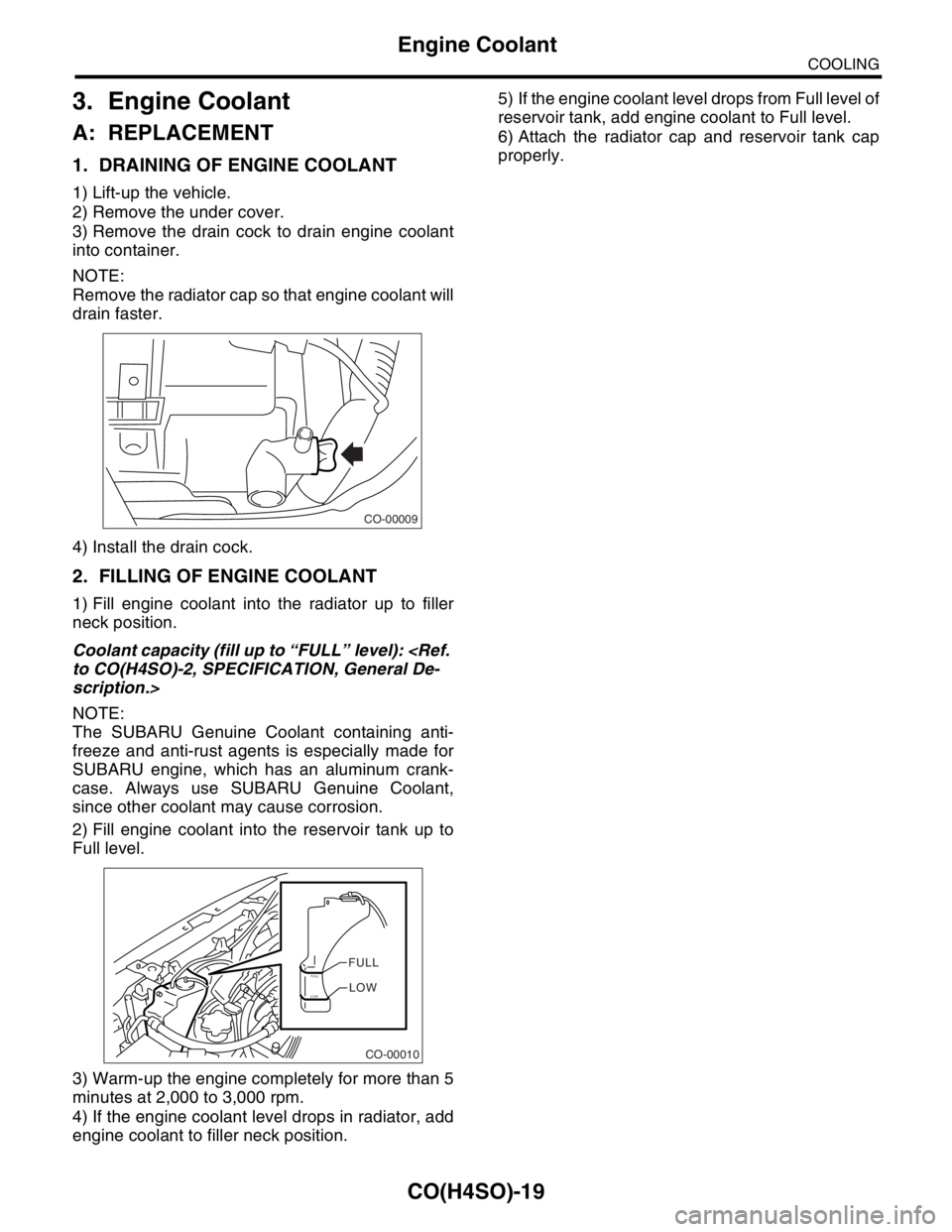
3) Remove the drain cock to drain engine coolant
into container.
NOTE:
Remove the radiator cap so that engine coolant will
drain faster.
4) Install the drain cock.
2. FILLING OF ENGINE COOLANT
1) Fill engine coolant into the radiator up to filler
neck position.
Coolant capacity (fill up to “FULL” level):
scription.>
NOTE:
The SUBARU Genuine Coolant containing anti-
freeze and anti-rust agents is especially made for
SUBARU engine, which has an aluminum crank-
case. Always use SUBARU Genuine Coolant,
since other coolant may cause corrosion.
2) Fill engine coolant into the reservoir tank up to
Full level.
3) Warm-up the engine completely for more than 5
minutes at 2,000 to 3,000 rpm.
4) If the engine coolant level drops in radiator, add
engine coolant to filler neck position.5) If the engine coolant level drops from Full level of
reservoir tank, add engine coolant to Full level.
6) Attach the radiator cap and reservoir tank cap
properly.
CO-00009
CO-00010
FULLFULLLOWLOW
Page 1004 of 2870

CO(H4SO)-21
COOLING
Water Pump
4. Water Pump
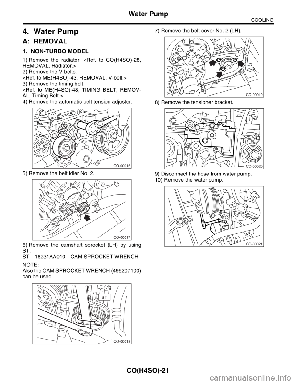
A: REMOVAL
1. NON-TURBO MODEL
1) Remove the radiator.
2) Remove the V-belts.
3) Remove the timing belt.
4) Remove the automatic belt tension adjuster.
5) Remove the belt idler No. 2.
6) Remove the camshaft sprocket (LH) by using
ST.
ST 18231AA010 CAM SPROCKET WRENCH
NOTE:
Also the CAM SPROCKET WRENCH (499207100)
can be used.7) Remove the belt cover No. 2 (LH).
8) Remove the tensioner bracket.
9) Disconnect the hose from water pump.
10) Remove the water pump.
CO-00016
CO-00017
CO-00018
ST
CO-00019
CO-00020
CO-00021
Page 1005 of 2870

CO(H4SO)-22
COOLING
Water Pump
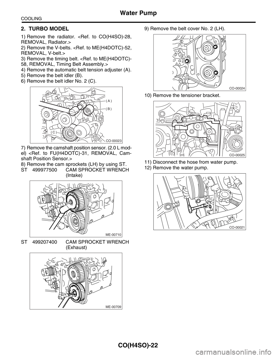
2. TURBO MODEL
1) Remove the radiator.
2) Remove the V-belts.
3) Remove the timing belt.
4) Remove the automatic belt tension adjuster (A).
5) Remove the belt idler (B).
6) Remove the belt idler No. 2 (C).
7) Remove the camshaft position sensor. (2.0 L mod-
el)
8) Remove the cam sprockets (LH) by using ST.
ST 499977500 CAM SPROCKET WRENCH
(Intake)
ST 499207400 CAM SPROCKET WRENCH
(Exhaust)9) Remove the belt cover No. 2 (LH).
10) Remove the tensioner bracket.
11) Disconnect the hose from water pump.
12) Remove the water pump.
CO-00023
(A)
(B)
(C)
ME-00710
ME-00709
CO-00024
CO-00025
CO-00021