Page 903 of 2870
ME(H4SO)-34
MECHANICAL
Engine Assembly
9. Engine Assembly
A: REMOVAL
1) Set the vehicle on lift arms.
2) Open the front hood fully, and then support with
the front hood stay.
3) Release the fuel pressure.
47, RELEASING OF FUEL PRESSURE, OPERA-
TION, Fuel.>
4) Disconnect the A/C pressure hoses from A/C
compressor.
5) Remove the fuel filler cap.
6) Disconnect the ground cable from battery.
7) Remove the air intake duct and air cleaner case.
Case.>
8) Remove the under cover.
9) Remove the radiator from vehicle.
CO(H4SO)-28, REMOVAL, Radiator.>
10) Remove the air cleaner case stay.
MT model
AT model11) Disconnect the following connectors and ca-
bles.
(1) Front oxygen (A/F) sensor connector
(2) Rear oxygen sensor connector
(3) Engine ground cable
FU-00009
ME-00204
ME-00205
EX-00029
EX-00030
ME-00206
Page 909 of 2870

ME(H4SO)-40
MECHANICAL
Engine Assembly
11) Tighten the nuts which hold lower side of trans-
mission to engine.
Tightening torque:
50 N
⋅m (5.1 kgf-m, 36.9 ft-lb)
12) Tighten the nuts which install front cushion rub-
ber onto crossmember.
Tightening torque:
85 N
⋅m (8.7 kgf-m, 63 ft-lb)
NOTE:
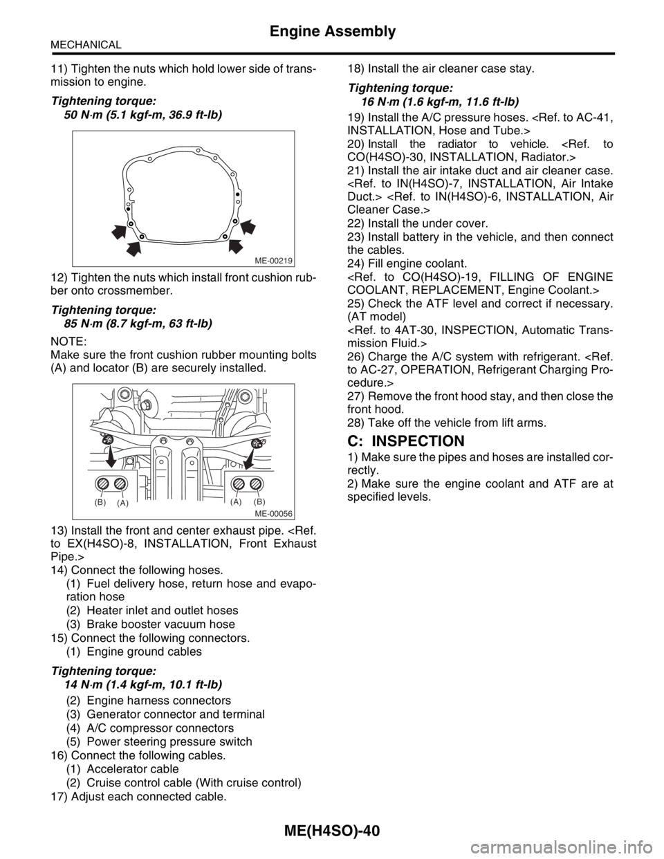
Make sure the front cushion rubber mounting bolts
(A) and locator (B) are securely installed.
13) Install the front and center exhaust pipe.
to EX(H4SO)-8, INSTALLATION, Front Exhaust
Pipe.>
14) Connect the following hoses.
(1) Fuel delivery hose, return hose and evapo-
ration hose
(2) Heater inlet and outlet hoses
(3) Brake booster vacuum hose
15) Connect the following connectors.
(1) Engine ground cables
Tightening torque:
14 N
⋅m (1.4 kgf-m, 10.1 ft-lb)
(2) Engine harness connectors
(3) Generator connector and terminal
(4) A/C compressor connectors
(5) Power steering pressure switch
16) Connect the following cables.
(1) Accelerator cable
(2) Cruise control cable (With cruise control)
17) Adjust each connected cable.18) Install the air cleaner case stay.
Tightening torque:
16 N
⋅m (1.6 kgf-m, 11.6 ft-lb)
19) Install the A/C pressure hoses.
INSTALLATION, Hose and Tube.>
20) Install the radiator to vehicle.
CO(H4SO)-30, INSTALLATION, Radiator.>
21) Install the air intake duct and air cleaner case.
Duct.>
Cleaner Case.>
22) Install the under cover.
23) Install battery in the vehicle, and then connect
the cables.
24) Fill engine coolant.
COOLANT, REPLACEMENT, Engine Coolant.>
25) Check the ATF level and correct if necessary.
(AT model)
mission Fluid.>
26) Charge the A/C system with refrigerant.
to AC-27, OPERATION, Refrigerant Charging Pro-
cedure.>
27) Remove the front hood stay, and then close the
front hood.
28) Take off the vehicle from lift arms.
C: INSPECTION
1) Make sure the pipes and hoses are installed cor-
rectly.
2) Make sure the engine coolant and ATF are at
specified levels.
ME-00219
ME-00056
(A)
(A)(B)
(B)
Page 984 of 2870

COOLING
CO(H4SO)
Page
1. General Description ....................................................................................2
2. Radiator Fan System ................................................................................13
3. Engine Coolant..........................................................................................19
4. Water Pump ..............................................................................................21
5. Thermostat ................................................................................................26
6. Radiator.....................................................................................................28
7. Radiator Cap .............................................................................................34
8. Radiator Main Fan and Fan Motor ............................................................35
9. Radiator Sub Fan and Fan Motor..............................................................40
10. Reservoir Tank ..........................................................................................41
11. Coolant Filler Tank ....................................................................................42
12. Engine Cooling System Trouble in General ..............................................43
Page 985 of 2870

CO(H4SO)-2
COOLING
General Description
1. General Description
A: SPECIFICATION
ModelNon-turbo Turbo
Cooling system Electric fan+Forced engine coolant circulation system
Total engine coolant capacity2(US qt, Imp qt)2.0L with ATF warmer:
Approx. 6.9 (7.29, 6.07)
2.0L AT:
Approx. 6.5 (6.87, 5.72)
2.0L MT:
Approx. 6.6 (6.98, 5.81)
2.5L AT:
Approx. 6.8 (7.19, 5.98)
2.5L MT:
Approx. 6.9 (7.29, 6.07)AT :
Approx. 7.3 (7.71, 6.42)
MT with oil cooler:
Approx. 7.3 (7.71, 6.42)
MT without oil cooler:
Approx. 7.4 (7.82, 6.51)
Water pumpType Centrifugal impeller type
Discharge perfor-
mance IDischarge 202 (5.3 US gal, 4.4 Imp gal)/min.
Pump speed — Discharge
pressure760 rpm — 2.9 kPa (0.3 mAq)
Engine coolant temperature 85°C (185°F)
Discharge perfor-
mance IIDischarge 1002 (26.4 US gal, 22.0 Imp gal)/min.
Pump speed — Discharge
pressure3,000 rpm — 49.0 kPa (5.0 mAq)
Engine coolant temperature 85°C (185°F)
Discharge perfor-
mance IIIDischarge 2002 (52.8 US gal, 44.0 Imp gal)/min.
Pump speed — Discharge
pressure6,000 rpm — 225.4 kPa (23.0 mAq)
Engine coolant temperature 85°C (185°F)
Impeller diameter 76 mm (2.99 in)
Number of impeller vanes 8
Pump pulley diameter 60 mm (2.36 in)
Clearance between
impeller and caseStandard 0.5 — 0.7 mm (0.020 — 0.028 in)
Limit 1.0 mm (0.039 in)
“Thrust” runout of impeller end 0.5 mm (0.020 in)
ThermostatType Wax pellet type
Starts to open 80 — 84°C (176 — 183°F) 76 — 80°C (169 — 176°F)
Fully opened 95°C (203°F) 91°C (196°F)
Valve lift 9.0 mm (0.354 in) or more
Valve bore 35 mm (1.38 in)
Radiator fanMotorMain fan 70 W2.0L AT (K4
★1) : 70 W
2.0L AT (EC, EK★1) :
120 W
2.0 L MT: 70 W
2.5 L: 120 W
Sub fan 70 W2.0L AT (K4
★1) : 70 W
2.0L AT (EC, EK★1) :
120 W
2.0 L MT: 70 W
2.5 L: 120 W
Fan diameter×Blade320 mm (11.81 in)×5 (main fan)
320 mm (11.81 in)×7 (sub fan)
Page 986 of 2870
CO(H4SO)-3
COOLING
General Description
★1: For option code, refer to ID section. RadiatorType Down flow, pressure type
Core dimensions Width×Height×Thickness691.5×360×16 mm
(27.22×14.17×0.63 in)
Pressure range in which cap valve is openAbove: 108±15 kPa
(1.1±0.15 kg/cm
2, 16±2 psi)
Below: −1.0 to −4.9 kPa
(−0.01 to −0.05 kg/cm
2, −0.1 to −0.7 psi)
Fins Corrugated fin type
Reservoir
tankCapacity 0.52 (0.5 US qt, 0.4 Imp qt)
Page 990 of 2870

CO(H4SO)-7
COOLING
General Description
2. RADIATOR AND RADIATOR FAN
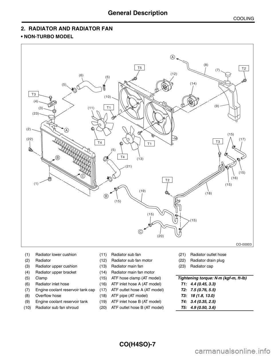
NON-TURBO MODEL
(1) Radiator lower cushion (11) Radiator sub fan (21) Radiator outlet hose
(2) Radiator (12) Radiator sub fan motor (22) Radiator drain plug
(3) Radiator upper cushion (13) Radiator main fan (23) Radiator cap
(4) Radiator upper bracket (14) Radiator main fan motor
(5) Clamp (15) ATF hose clamp (AT model)Tightening torque: N
⋅m (kgf-m, ft-lb)
(6) Radiator inlet hose (16) ATF inlet hose A (AT model)T1: 4.4 (0.45, 3.3)
(7) Engine coolant reservoir tank cap (17) ATF outlet hose A (AT model)T2: 7.5 (0.76, 5.5)
(8) Overflow hose (18) ATF pipe (AT model)T3: 18 (1.8, 13.0)
(9) Engine coolant reservoir tank (19) ATF inlet hose B (AT model)T4: 3.4 (0.35, 2.5)
(10) Radiator sub fan shroud (20) ATF outlet hose B (AT model)T5: 4.9 (0.50, 3.6)
CO-00003
(9)
(1)(10)(8)
(2)
T3
T2
T2
T4
T4(14)
(20) (22)(3) (4)
(19)(16)
(18)(7)
(17)
(15) (15)
(15)
(15) (15) (15)(12)
(11)
(13)
T5
T1
T1
(5) (5)
(5)(6)
(21)
A
A
C
T3
B
B
C
(23)
Page 992 of 2870

CO(H4SO)-9
COOLING
General Description
(1) Radiator lower cushion (18) ATF pipe (AT model) (31) Oil cooler inlet hose B (MT model
with oil cooler)
(2) Radiator (19) ATF inlet hose B (AT model)
(3) Radiator upper cushion (20) ATF outlet hose B (AT model) (32) Oil cooler outlet hose B (MT
model with oil cooler)
(4) Radiator upper bracket (21) Radiator outlet hose
(5) Clamp (22) Radiator drain plug (33) Spacer (MT model with oil cooler)
(6) Radiator inlet hose (23) Engine coolant filler tank (34) Cushion (MT model with oil
cooler)
(7) Engine coolant reservoir tank cap (24) Engine coolant filler tank cap
(8) Over flow hose (25) Engine overflow hose (35) Setting washer (MT model with oil
cooler)
(9) Engine coolant reservoir tank (26) Radiator under cover (AT model)
(10) Radiator fan shroud (27) Engine air breather hose
(11) Radiator sub fan (28) Oil cooler inlet hose A (MT model
with oil cooler)Tightening torque: N
⋅m (kgf-m, ft-lb)
(12) Radiator sub fan motorT1: 4.4 (0.45, 3.3)
(13) Radiator main fan (29) Oil cooler outlet hose A (MT
model with oil cooler)T2: 7.5 (0.76, 5.5)
(14) Radiator main fan motorT3: 18 (1.8, 13.0)
(15) ATF hose clamp (AT model) (30) Oil cooler pipe (MT model with oil
cooler)T4: 3.4 (0.35, 2.5)
(16) ATF inlet hose A (AT model)T5: 4.9 (0.50, 3.6)
(17) ATF outlet hose A (AT model)
Page 996 of 2870

CO(H4SO)-13
COOLING
Radiator Fan System
2. Radiator Fan System
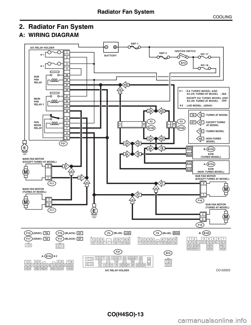
A: WIRING DIAGRAM
CO-02003
B72 SBF-1
SBF-4
NO.17
NO.18
MAIN FAN MOTOR
(EXCEPT TURBO AT MODEL)
F17
2
1
ET
MAIN
FA N
RELAY-1
FA N
MODE
RELAY31
34
32
30
5
9
7
8
6 SUB
FA N
RELAY A/C RELAY HOLDER
28
25
3
4
27
29
RHD
RHD
RHD
RHDLHD
LHD
LHD
F2
B1001110F2
B100197
2
1
F27
B25
B24
A14
ECM
(NON- TURBO MODEL)B134 A:
A13
NA
F17
F16
21
LHD
RHD
F2(BLACK)
(BLACK) (GRAY)
(GRAY)F2
A/C RELAY HOLDER
F27
12
34
567891110
1312142120
2322243130
333234
1615171819
26252728293536
B:B135
A:
B134
1234567891011121314151617181920212223242526272829303132333435
: : ::
ET
TA
1234 5678910 11 12 13 14 15 16 17 18 19 2012345
678910
11 12 19 20 2113 14 15 16 17 18 22
B135 B:
ECM
(TURBO MODEL)
(BLUE)
(BLUE)
567 2 134
2910
1112131415252416
30
98171819202821222332312627333435
: TURBO MODELTB
: NON-TURBO
MODEL
NA: TURBO AT MODEL
TA
: EXCEPT TURBO
AT MODEL
ET
: KA TURBO MODEL AND
EC,EK TURBO AT MODEL : 30A 1*
1*
1*
: LHD MODEL : (GRAY) 2*
2*
SUB FAN MOTOR
(TURBO AT MODEL)
F16
1
2
MAIN FAN MOTOR
(TURBO AT MODEL)
F17
1
2
SUB FAN MOTOR
(EXCEPT TURBO AT MODEL)
F16
2
1
TA
ET
TA
TA
LHD
TA
ET
ET
TBNA
TB
12
F17
F16TA
:
TA
ET
:
ET
E
EXCEPT KA TURBO MODEL AND
EC,EK TURBO AT MODEL: 20A
IGNITION SWITCH
BATTERY
3412
B72