2004 SUBARU FORESTER relay
[x] Cancel search: relayPage 1648 of 2870

EN(H4DOTC)-18
ENGINE (DIAGNOSTIC)
Electrical Component Location
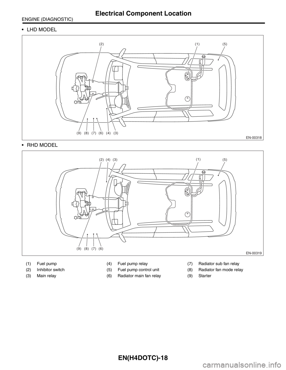
LHD MODEL
RHD MODEL
(1) Fuel pump (4) Fuel pump relay (7) Radiator sub fan relay
(2) Inhibitor switch (5) Fuel pump control unit (8) Radiator fan mode relay
(3) Main relay (6) Radiator main fan relay (9) Starter
EN-00318
(1)
(9)
(2)
(3) (4) (7) (8) (6)
(5)
EN-00319
(1)
(9) (7)(8) (6)
(2)(5)(3)(4)
Page 1655 of 2870

EN(H4DOTC)-25
ENGINE (DIAGNOSTIC)
Engine Control Module (ECM) I/O Signal
Sensor power supply B136 16 5 5 —
Oil flow
control
solenoid
valve RHSignal (+) B134 18ON: 10 — 13
OFF: 0ON: 13 — 14
OFF: 0—
Signal (−) B134 28 0 0 —
Oil flow
control
solenoid
valve LHSignal (+) B134 19ON: 10 — 13
OFF: 0ON: 13 — 14
OFF: 0—
Signal (−) B134 29 0 0 —
Ignition
control#1 B135 18 0 13 — 14 Waveform
#2 B135 17 0 13 — 14 Waveform
#3 B135 16 0 13 — 14 Waveform
#4 B135 15 0 13 — 14 Waveform
Fuel injec-
tor#1 B136 6 10 — 13 1 — 14 Waveform
#2 B136 5 10 — 13 1 — 14 Waveform
#3 B136 4 10 — 13 1 — 14 Waveform
#4 B136 3 10 — 13 1 — 14 Waveform
Idle air
control
solenoid
valveSignal B134 27 0 or 13 — 14 0 or 13 — 14 Waveform
Fuel pump
control unitDiagnosis
signalB137 28 10 — 13 13 — 14 Waveform
Control
signalB135 27 0 or 5 0 or 5 —
A/C relay control B135 33ON: 0.5, or less
OFF: 10 — 13ON: 0.5, or less
OFF: 13 — 14—
Radiator fan relay 1 con-
trolB135 25ON: 0.5, or less
OFF: 10 — 13ON: 0.5, or less
OFF: 13 — 14—
Radiator fan relay 2 con-
trolB135 24ON: 0.5, or less
OFF: 10 — 13ON: 0.5, or less
OFF: 13 — 14Model with A/C
Malfunction indicator
lightB134 17 — —Light “ON”: 1, or less
Light “OFF”: 10 — 14
Engine speed output B134 23 — 0 — 13, or more Waveform
Purge control solenoid
valveB134 14ON: 1, or less
OFF: 10 — 13ON: 1, or less
OFF: 13 — 14Wavefor m
Manifold
absolute
pressure
sensorSignal B136 22 1.7 — 2.4 1.1 — 1.6
— Pow er
supplyB136 16 5 5
GND
(sensors)B136 35 0 0
Fuel level sensor B136 20 0.12 — 4.75 0.12 — 4.75 —
Small light switch B137 12ON: 0
OFF: 10 — 13ON: 0
OFF: 13 — 14—
Blower fan switch B137 13ON: 0
OFF: 10 — 13ON: 0
OFF: 13 — 14—
Rear defogger switch B137 11ON: 0
OFF: 10 — 13ON: 0
OFF: 13 — 14—
Power steering oil pres-
sure switchB137 10 10 — 13ON: 0
OFF: 13 — 14—
Wiper switch B137 23ON: 10 — 13
OFF: 0ON: 13 — 14
OFF: 0— DESCRIPTION Connector No. Terminal No.Signal (V)
NOTE
Ignition SW ON
(engine OFF)Engine ON
(Idling)
Page 1665 of 2870

EN(H4DOTC)-35
ENGINE (DIAGNOSTIC)
Subaru Select Monitor
NOTE:
For detailed operation procedure, refer to the “SUBARU SELECT MONITOR OPERATION MANUAL”.
5. READ CURRENT DATA FOR ENGINE (OBD MODE)
1) On the «Main Menu» display screen, select the {Each System Check} and press the [YES] key.
2) On the «System Selection Menu» display screen, select the {Engine} and press the [YES] key.
3) Press the [YES] key after the information of engine type was displayed.
4) On the «Engine Diagnosis» display screen, select the {OBD System} and press the [YES] key.
5) On the «OBD Menu» screen, select the {Current Data Display/Save}, and then press the [YES] key.
6) On the «Data Display Menu» screen, select the {Data Display} and press the [YES] key.
7) Using the scroll key, move the display screen up or down until the desired data is shown.
A list of the support data is shown in the following table.
Air conditioning signal A/C Compressor Signal ON or OFF
Radiator main fan relay signal Radiator Fan Relay #1 ON or OFF
Knocking signal Knocking Signal ON or OFF
Radiator sub fan relay signal Radiator Fan Relay #2 ON or OFF
Power steering switch signal P/S Switch ON or OFF
Engine torque control permission signal Torque Permission Signal ON or OFF
Rear oxygen sensor rich signal Rear Oxygen Rich Signal ON or OFF
Starter switch signal Starter Switch ON or OFF
Idle switch signal Idle Switch ON or OFF
Crankshaft position sensor signal Crankshaft Position Sig. ON or OFF
Camshaft position sensor signal Camshaft Position Sig. ON or OFF
Rear defogger switch signal Rear Defogger SW ON or OFF
Blower fan switch signal Blower Fan SW ON or OFF
Small light switch signal Light Switch ON or OFF
Tumble generated valve output signal TGV Output ON or OFF
Exhaust temperature signal Exhaust Gas Temperature°C
Estimated cumulative driving distance Odd Meter km
Roughness Monitor for #1 cylinder Roughness Monitor #1 —
Roughness Monitor for #2 cylinder Roughness Monitor #2 —
Roughness Monitor for #3 cylinder Roughness Monitor #3 —
Roughness Monitor for #4 cylinder Roughness Monitor #4 —
Wiper switch signal Wiper Switch ON or OFF
A/C middle pressure switch signal A/C Mid pressure switch ON or OFF
AT retard angle demand signal Retard Signal from AT ON or OFF
AT fuel cut demand signal Fuel Cut Signal from AT ON or OFF
Description Display Unit of measure
Number of diagnosis code Number of Diag. Code —
Condition of malfunction indicator light MI (MIL) ON or OFF
Monitoring test of misfire Misfire monitoring Complete or incomplete
Monitoring test of fuel system Fuel system monitoring Complete or incomplete
Monitoring test of comprehensive component Component monitoring Complete or incomplete
Test of catalyst Catalyst Diagnosis Complete or incomplete
Test of heating-type catalyst Heated catalyst No support
Test of evaporative emission purge control system Evaporative purge system No support
Test of secondary air system Secondary air system No support
Test of air conditioning system refrigerant A/C system refrigerant No support
Test of oxygen sensor Oxygen sensor Complete or incomplete
Test of oxygen sensor heater Oxygen Heater Diagnosis Complete or incomplete
Test of EGR system EGR system No supportRemarks Display Unit of measure
Page 1667 of 2870
![SUBARU FORESTER 2004 Service Repair Manual EN(H4DOTC)-37
ENGINE (DIAGNOSTIC)
Subaru Select Monitor
7. LED OPERATION MODE FOR ENGINE
1) On the «Main Menu» display screen, select the {Each System Check} and press the [YES] key.
2) On the «Sys SUBARU FORESTER 2004 Service Repair Manual EN(H4DOTC)-37
ENGINE (DIAGNOSTIC)
Subaru Select Monitor
7. LED OPERATION MODE FOR ENGINE
1) On the «Main Menu» display screen, select the {Each System Check} and press the [YES] key.
2) On the «Sys](/manual-img/17/57426/w960_57426-1666.png)
EN(H4DOTC)-37
ENGINE (DIAGNOSTIC)
Subaru Select Monitor
7. LED OPERATION MODE FOR ENGINE
1) On the «Main Menu» display screen, select the {Each System Check} and press the [YES] key.
2) On the «System Selection Menu» display screen, select the {Engine} and press the [YES] key.
3) Press the [YES] key after the information of engine type was displayed.
4) On the «Engine Diagnosis» screen, select the {Current Data Display/Save}, and then press the [YES] key.
5) On the «Data Display» screen, select the {Data & LED Display} and press the [YES] key.
6) Using the scroll key, move the display screen up or down until the desired data is shown.
A list of the support data is shown in the following table.
NOTE:
For detailed operation procedure, refer to the “SUBARU SELECT MONITOR OPERATION MANUAL”.
Description Display Message LED “ON” requirements
Ignition switch signal Ignition Switch ON or OFF When ignition switch is ON.
Test mode connector signal Test Mode Signal ON or OFF When test mode connector is connected.
Neutral position switch signal Neutral Position Switch ON or OFF When neutral position signal is entered.
Air conditioning switch signal A/C Switch ON or OFF When air conditioning switch is ON.
Air conditioning relay signal A/C Compressor Signal ON or OFF When air conditioning relay is in function.
Radiator main fan relay signal Radiator Fan Relay #1 ON or OFF When radiator main fan relay is in function.
Knocking signal Knocking Signal ON or OFF When knocking signal is input.
Radiator sub fan relay signal Radiator Fan Relay #2 ON or OFF When radiator sub fan relay is in function.
Engine torque control permission
signalTorque Control Permission ON or OFFWhen engine torque control permission sig-
nal is entered.
Rear oxygen sensor rich signalRear O
2 Rich Signal
ON or OFFWhen rear oxygen sensor mixture ratio is
rich.
Starter switch signal Starter Switch ON or OFF When starter switch signal is entered.
Idle switch signal Idle Switch ON or OFF When idle switch signal is entered.
Crankshaft position sensor signal Crankshaft Position Signal ON or OFFWhen crankshaft position sensor signal is
input.
Camshaft position sensor signal Camshaft Position Signal ON or OFFWhen camshaft position sensor signal is
entered.
Power steering switch signal P/S Switch ON or OFF When power steering switch is entered.
Rear defogger switch signal Rear Defogger Switch ON or OFF When rear defogger switch is ON.
Blower fan switch signal Blower Fan Switch ON or OFF When blower fan switch is ON.
Light switch signal Light Switch ON or OFF When small light switch is ON.
Wiper switch signal Wiper Switch ON or OFF When wiper switch is ON.
A/C middle pressure switch signal A/C Mid Pressure Switch ON or OFF When A/C switch is ON.
AT retard angle demand signal Retard Signal from AT ON or OFF When AT retard angle demand signal exists.
AT fuel cut demand signal Fuel Cut Signal from AT ON or OFF When AT fuel cut demand signal exists.
AT/MT identification signal AT Vehicle ID Signal ON or OFF For AT model
Tumble generated valve actuator
signalTGV Output ON or OFF When TGV actuator signal is output.
Tumble generated valve drive sig-
nalTGV DriveOPEN or
CLOSEWhen TGV moves and valve opens.
Page 1679 of 2870
![SUBARU FORESTER 2004 Service Repair Manual EN(H4DOTC)-49
ENGINE (DIAGNOSTIC)
Compulsory Valve Operation Check Mode
13) Pressing the [NO] key completes the compul-
sory operation check mode.The display will then re-
turn to the «Actuator ON/OF SUBARU FORESTER 2004 Service Repair Manual EN(H4DOTC)-49
ENGINE (DIAGNOSTIC)
Compulsory Valve Operation Check Mode
13) Pressing the [NO] key completes the compul-
sory operation check mode.The display will then re-
turn to the «Actuator ON/OF](/manual-img/17/57426/w960_57426-1678.png)
EN(H4DOTC)-49
ENGINE (DIAGNOSTIC)
Compulsory Valve Operation Check Mode
13) Pressing the [NO] key completes the compul-
sory operation check mode.The display will then re-
turn to the «Actuator ON/OFF Operation» screen.
A list of the support data is shown in the following
table.
NOTE:
The following parts will be displayed but not func-
tional.
For detailed operation procedure, refer to the
“SUBARU SELECT MONITOR OPERATION MAN-
UAL”.
Description Display
Compulsory fuel pump relay operation
checkFuel Pump
Compulsory radiator fan relay operation
checkRadiator Fan
Relay
Compulsory air conditioning relay oper-
ation checkA/C Compressor
Relay
Compulsory purge control solenoid
valve operation checkCPC Solenoid
Compulsory wastegate control sole-
noid valve operation checkWastegate con-
trol solenoid
Display
EGR Solenoid
ASV Solenoid
PCV Solenoid
Vent Control Solenoid
FICD Solenoid
Pressure Switching Solenoid1
Pressure Switching Solenoid2
EXH. Bypass Control Permit Flag
AAI Solenoid
Atmospheric pressure switching solenoid
Page 1692 of 2870

EN(H4DOTC)-62
ENGINE (DIAGNOSTIC)
Diagnostics for Engine Starting Failure
C: CHECK POWER SUPPLY AND GROUND LINE OF ENGINE CONTROL MOD-
ULE (ECM)
CAUTION:
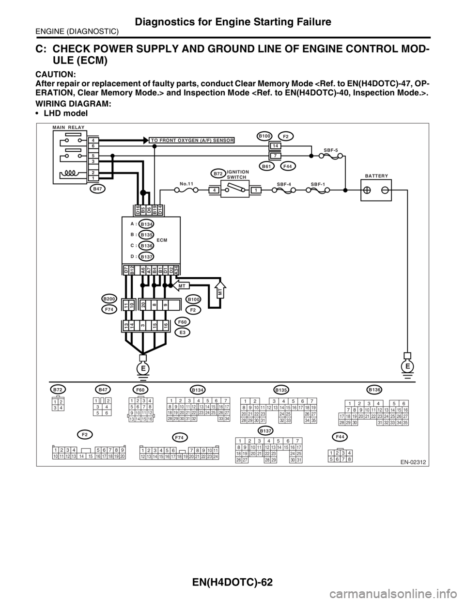
After repair or replacement of faulty parts, conduct Clear Memory Mode
WIRING DIAGRAM:
LHD model
EN-02312
F74
B72
34
12
BATTERYIGNITION
SWITCH MAIN RELAY
SBF-4SBF-1
SBF-5
B72 TO FRONT OXYGEN (A/F) SENSOR
D16 D7
B12
A6
A7
B4
B1
D1
D2
A34B5
D6
B19
D14
No.11
B61F44
B47
B100
F2
E3 F60 1 2 3 5 6 4
ECM
EE
14
B134
B137 B135 A :
B :
C :B136
D :
14
7
3412
56
123
4
56
78
9
1011 12
1314 15 16
F60B47
B137
F2
B100F2
11
10
20
8
9 13
14
3
15
16
B135
F44
567
82 1
94 310
24 22 23 2511 12 13 14 15
26 27
2816 17 18 19
20 21
29 30 31 32 33 34 35
12345678
34
12 8910 11
12 13 14 15 16 17 18 19 20 21 22 23 2456 71234 5678910 11 12 13 14 15 16 17 18 19 20
567
82 1
94 310
22 23 11 12 13 14 15
24 25
2616 17
18 19 20 21
27 28 29 30 31
F74 B200
MT
MT
B134
56 7
82 1
94 310
24 22 23 25 11 12 13 14 15
26 27
2816 17
18 19 20 21
33 34 29
32 30 31
B136
56
782 1
94 310
24 22 23 2511 12 13
1415
26 27
2816
17 18 19 20 21
33 34 29
32 30
31 35
Page 1693 of 2870

EN(H4DOTC)-63
ENGINE (DIAGNOSTIC)
Diagnostics for Engine Starting Failure
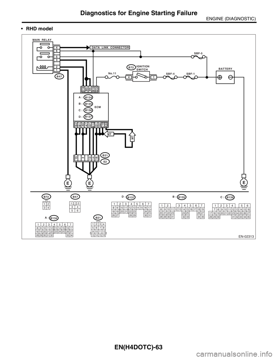
RHD model
B72B136
34
12
BATTERYIGNITION
SWITCH MAIN RELAY
SBF-4SBF-1
SBF-5
B72 DATA LINK CONNECTOR
D16 B4
B1
A6
A7
D7
B12
D1
D2
C19B5
B6
B19
D14
No.11B47
E2 B21 1 2 3 5 6 4
ECM
14
B134
B135
B136 A :
B :
C :
B137
D :
15
3
16 14 13
3412
56
123
4
56
78
9
1011 12
1314 15 16
B134B21
B47B135B137
EN-02313
E
E E
567
82 1
94 310
24 22 23 2511 12 13 14 15
26 27
2816 17 18 19
20 21
29 30 31 32 33 34 35
567
82 1
94 310
22 23 11 12 13 14 15
24 25
2616 17
18 19 20 21
27 28 29 30 31
A34
MTMT
56
782 1
94 310
24 22 23 2511 12 13
1415
26 27
2816
17 18 19 20 21
33 34 29
32 30
31 35
56 7
82 1
94 310
24 22 23 25 11 12 13 14 15
26 27
2816 17
18 19 20 21
33 34 29
32 30 31
D :
B :
C :
A :
Page 1694 of 2870

EN(H4DOTC)-64
ENGINE (DIAGNOSTIC)
Diagnostics for Engine Starting Failure
Step Check Yes No
1 CHECK MAIN RELAY.
1) Turn the ignition switch to OFF.
2) Remove the main relay.
3) Connect the battery to main relay terminals
No. 1 and No. 2.
4) Measure the resistance between main relay
terminals.
Te r m i n a l s
No. 3 — No. 5:
No. 4 — No. 6:Is the resistance less than 10
Ω?Go to step 2.Replace the main
relay.
2 CHECK GROUND CIRCUIT FOR ECM.
1) Disconnect the connector from ECM.
2) Measure the resistance of harness
between ECM and chassis ground.
Connector & terminal
(B134) No. 6 — Chassis ground:
(B134) No. 7 — Chassis ground:
(B134) No. 34 — Chassis ground:
(B135) No. 1 — Chassis ground:
(B135) No. 12 — Chassis ground:
(B137) No. 1 — Chassis ground:
(B137) No. 2 — Chassis ground:
(B137) No. 7 — Chassis ground:
(B134) No. 34 — Chassis ground: (MT
model)Is the resistance less than 5
Ω?Go to step 3.Repair open circuit
in harness
between ECM
connector and
engine ground ter-
minal.
3 CHECK INPUT VOLTAGE OF ECM.
Measure the voltage between ECM connector
and chassis ground.
Connector & terminal
(B135) No. 19 (+) — Chassis ground (
−):Is the voltage more than 10 V? Go to step 4.Repair open or
ground short cir-
cuit of power sup-
ply circuit.
4 CHECK INPUT VOLTAGE OF ECM.
1) Turn the ignition switch to ON.
2) Measure the voltage between ECM con-
nector and chassis ground.
Connector & terminal
(B137) No. 14 (+) — Chassis ground (
−):Is the voltage more than 10 V? Go to step 5.Repair open or
ground short cir-
cuit of power sup-
ply circuit.
5 CHECK INPUT VOLTAGE OF MAIN RELAY.
Measure the voltage between main relay con-
nector and chassis ground.
Connector & terminal
(B47) No. 1 (+) — Chassis ground (
−):
(B47) No. 5 (+) — Chassis ground (
−):
(B47) No. 6 (+) — Chassis ground (
−):Is the voltage more than 10 V? Go to step 6.Repair open or
ground short cir-
cuit of power sup-
ply circuit.
6 CHECK INPUT VOLTAGE OF ECM.
1) Connect the main relay and ECM connec-
tor.
2) Turn the ignition switch to ON.
3) Measure the voltage between ECM con-
nector and chassis ground.
Connector & terminal
(B135) No. 5 (+) — Chassis ground (
−):
(B135) No. 6 (+) — Chassis ground (
−):
(B137) No. 16 (+) — Chassis ground (
−):Is the voltage more than 10 V? Check ignition
control system.
IGNITION CON-
TROL SYSTEM,
Diagnostics for
Engine Starting
Fa il u r e. >Repair open or
ground short cir-
cuit in harness
between ECM
connector and
main relay connec-
tor.