2004 SUBARU FORESTER relay
[x] Cancel search: relayPage 1412 of 2870
FU(H4DOTC)-57
FUEL INJECTION (FUEL SYSTEM)
Fuel Tank
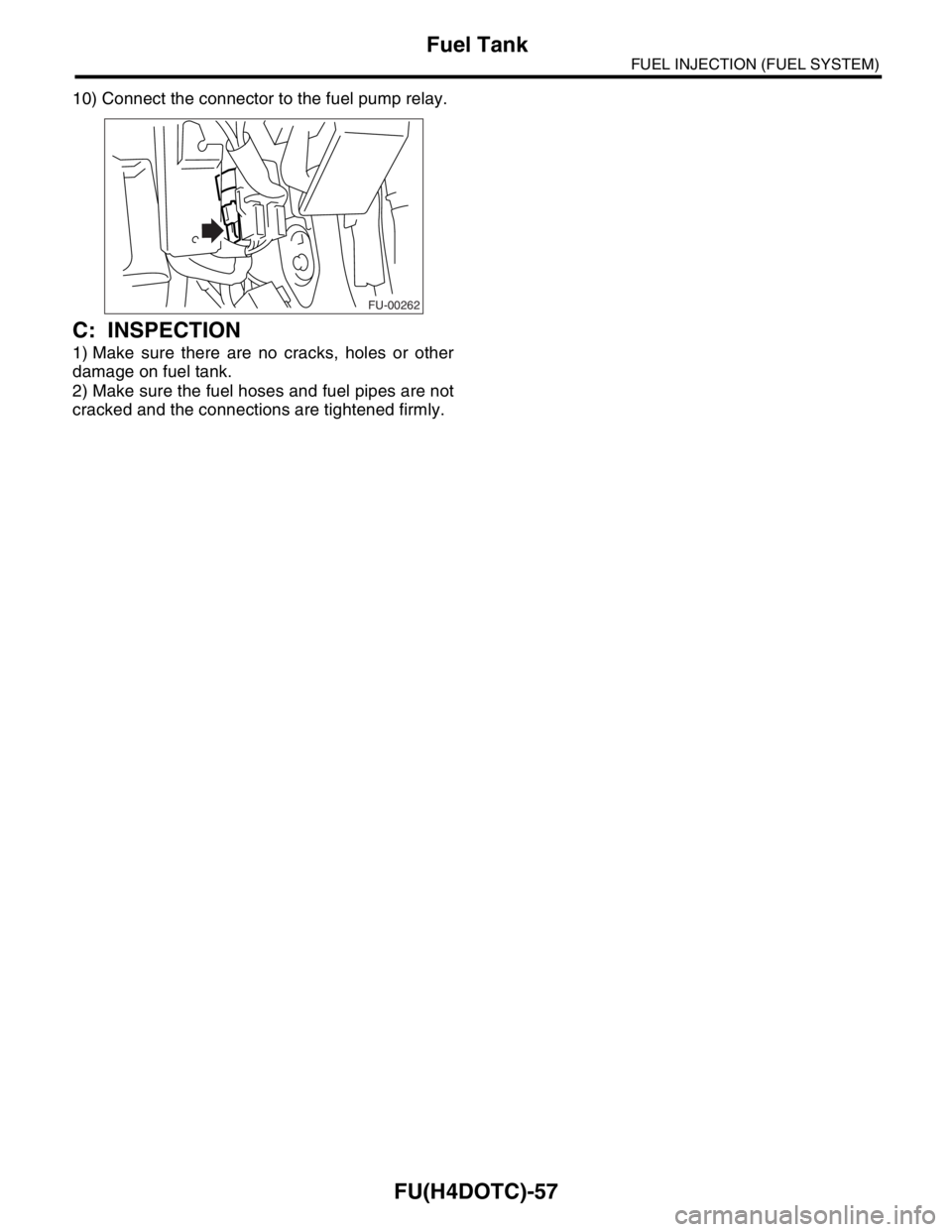
10) Connect the connector to the fuel pump relay.
C: INSPECTION
1) Make sure there are no cracks, holes or other
damage on fuel tank.
2) Make sure the fuel hoses and fuel pipes are not
cracked and the connections are tightened firmly.
FU-00262
Page 1415 of 2870
FU(H4DOTC)-60
FUEL INJECTION (FUEL SYSTEM)
Fuel Filler Pipe
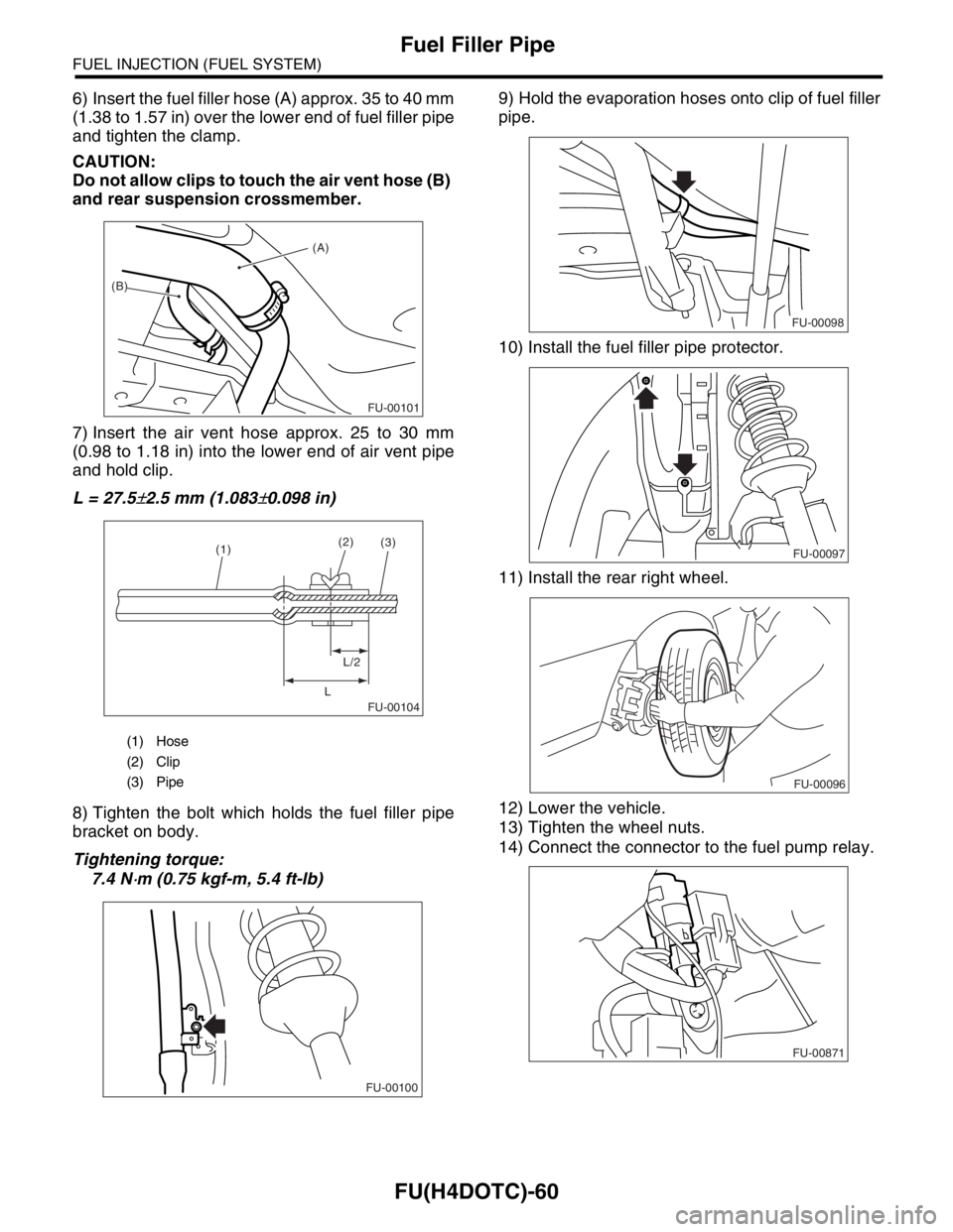
6) Insert the fuel filler hose (A) approx. 35 to 40 mm
(1.38 to 1.57 in) over the lower end of fuel filler pipe
and tighten the clamp.
CAUTION:
Do not allow clips to touch the air vent hose (B)
and rear suspension crossmember.
7) Insert the air vent hose approx. 25 to 30 mm
(0.98 to 1.18 in) into the lower end of air vent pipe
and hold clip.
L = 27.5
±2.5 mm (1.083±0.098 in)
8) Tighten the bolt which holds the fuel filler pipe
bracket on body.
Tightening torque:
7.4 N
⋅m (0.75 kgf-m, 5.4 ft-lb)9) Hold the evaporation hoses onto clip of fuel filler
pipe.
10) Install the fuel filler pipe protector.
11) Install the rear right wheel.
12) Lower the vehicle.
13) Tighten the wheel nuts.
14) Connect the connector to the fuel pump relay.
(1) Hose
(2) Clip
(3) Pipe
(A)
(B)
FU-00101
FU-00104
(1)(2)
L/2
L(3)
FU-00100
FU-00098
FU-00097
FU-00096
FU-00871
Page 1492 of 2870
ME(H4DOTC)-36
MECHANICAL
Fuel Pressure
7. Fuel Pressure
A: INSPECTION
CAUTION:
Before removing the fuel pressure gauge, re-
lease the fuel pressure.
NOTE:
If out of specification, check or replace the pressure
regulator and pressure regulator vacuum hose.
1) Release the fuel pressure.
SURE, OPERATION, Fuel.>
2) Open the fuel filler flap lid, and then remove the
fuel filler cap.
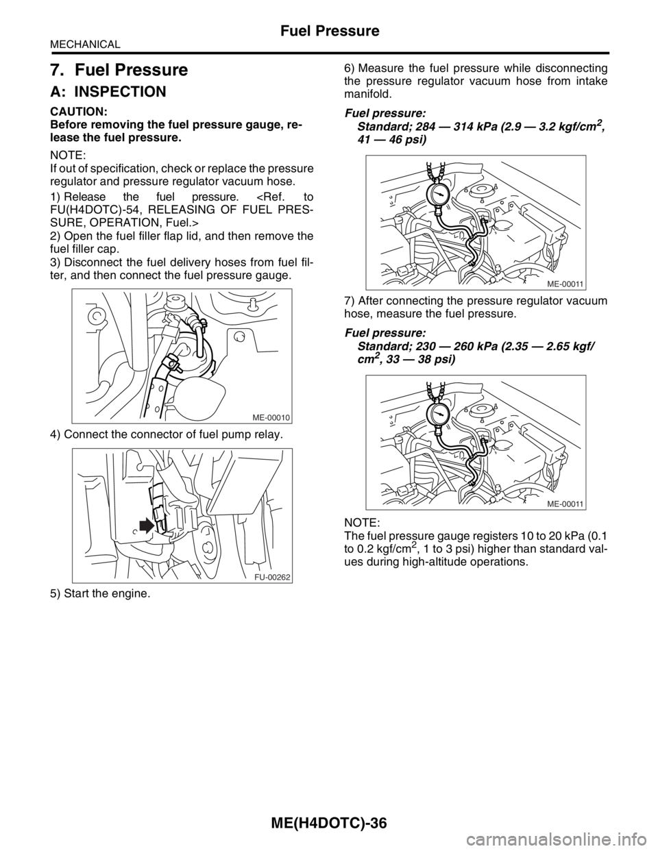
3) Disconnect the fuel delivery hoses from fuel fil-
ter, and then connect the fuel pressure gauge.
4) Connect the connector of fuel pump relay.
5) Start the engine.6) Measure the fuel pressure while disconnecting
the pressure regulator vacuum hose from intake
manifold.
Fuel pressure:
Standard; 284 — 314 kPa (2.9 — 3.2 kgf/cm2,
41 — 46 psi)
7) After connecting the pressure regulator vacuum
hose, measure the fuel pressure.
Fuel pressure:
Standard; 230 — 260 kPa (2.35 — 2.65 kgf/
cm
2, 33 — 38 psi)
NOTE:
The fuel pressure gauge registers 10 to 20 kPa (0.1
to 0.2 kgf/cm
2, 1 to 3 psi) higher than standard val-
ues during high-altitude operations.
ME-00010
FU-00262
ME-00011
ME-00011
Page 1499 of 2870
ME(H4DOTC)-41
MECHANICAL
Engine Assembly
9. Engine Assembly
A: REMOVAL
1) Set the vehicle on a lift.
2) Open the front hood fully, and then support with
the hood stay.
3) Collect the refrigerant from A/C system.
4) Release the fuel pressure.
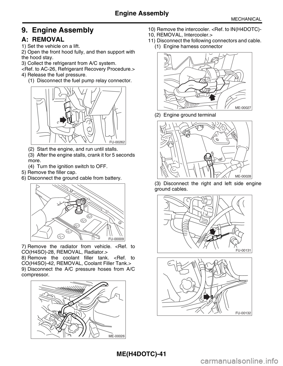
(1) Disconnect the fuel pump relay connector.
(2) Start the engine, and run until stalls.
(3) After the engine stalls, crank it for 5 seconds
more.
(4) Turn the ignition switch to OFF.
5) Remove the filler cap.
6) Disconnect the ground cable from battery.
7) Remove the radiator from vehicle.
8) Remove the coolant filler tank.
9) Disconnect the A/C pressure hoses from A/C
compressor.10) Remove the intercooler.
11) Disconnect the following connectors and cable.
(1) Engine harness connector
(2) Engine ground terminal
(3) Disconnect the right and left side engine
ground cables.
FU-00262
FU-00009
ME-00026
ME-00027
ME-00028
FU-00131
FU-00132
Page 1578 of 2870

ME(H4DOTC)-118
MECHANICAL
Engine Trouble in General
25.Engine Trouble in General
A: INSPECTION
NOTE:
“RANK” shown in the chart refers to the possibility of reason for the trouble in order (“Very often” to “Rarely”)
A — Very often
B — Sometimes
C — Rarely
TROUBLE PROBLEM PARTS, ETC. POSSIBLE CAUSE RANK
1. Engine will not start.
1) Starter does not turn. Starter Defective battery-to-starter harness B
Defective starter switch C
Defective inhibitor switch or neutral switch C
Defective starter B
Battery Poor terminal connection A
Run-down battery A
Defective charging system B
Friction Seizure of crankshaft and connecting rod bearing C
Seized camshaft C
Seized or stuck piston and cylinder C
2) Initial combustion does
not occur. Starter Defective starter C
Engine control system
Fuel line Defective fuel pump and relay A
Lack of or insufficient fuel B
Belt Defective (deterioration, etc.) B
Defective timing B
Compression Incorrect valve clearance C
Loosened spark plugs or defective gasket C
Loosened cylinder head bolts or defective gasket C
Improper valve seating C
Defective valve stem C
Worn or broken valve spring B
Worn or stuck piston rings, cylinder and piston C
Incorrect valve timing B
Improper engine oil (low viscosity) B
3) Initial combustion occurs. Engine control system
Intake system Defective intake manifold gasket B
Defective throttle body gasket B
Fuel line Defective fuel pump and relay C
Clogged fuel line C
Lack of or insufficient fuel B
Belt Defective (deterioration, etc.) B
Defective timing B
Compression Incorrect valve clearance C
Loosened spark plugs or defective gasket C
Loosened cylinder head bolts or defective gasket C
Improper valve seating C
Defective valve stem C
Worn or broken valve spring B
Worn or stuck piston rings, cylinder and piston C
Incorrect valve timing B
Improper engine oil (low viscosity) B
Page 1579 of 2870

ME(H4DOTC)-119
MECHANICAL
Engine Trouble in General
4) Engine stalls after initial
combustion. Engine control system
Intake system Loosened or cracked intake duct B
Loosened or cracked PCV hose C
Loosened or cracked vacuum hose C
Defective intake manifold gasket B
Defective throttle body gasket B
Dirty air cleaner element C
Fuel line Clogged fuel line C
Lack of or insufficient fuel B
Belt Defective (deterioration, etc.) B
Defective timing B
Compression Incorrect valve clearance C
Loosened spark plugs or defective gasket C
Loosened cylinder head bolts or defective gasket C
Improper valve seating C
Defective valve stem C
Worn or broken valve spring B
Worn or stuck piston rings, cylinder and piston C
Incorrect valve timing B
Improper engine oil (low viscosity) B
2. Rough idle and engine
stallEngine control system
Intake system Loosened or cracked intake duct A
Loosened or cracked PCV hose A
Loosened or cracked vacuum hose A
Defective intake manifold gasket B
Defective throttle body gasket B
Defective PCV valve C
Loosened oil filler cap B
Dirty air cleaner element C
Fuel line Defective fuel pump and relay C
Clogged fuel line C
Lack of or insufficient fuel B
Belt Defective timing C
Compression Incorrect valve clearance B
Loosened spark plugs or defective gasket B
Loosened cylinder head bolts or defective gasket B
Improper valve seating B
Defective valve stem C
Worn or broken valve spring B
Worn or stuck piston rings, cylinder and piston B
Incorrect valve timing A
Improper engine oil (low viscosity) B
Lubrication system Incorrect oil pressure B
Defective rocker cover gasket C
Cooling system Overheating C
Others Malfunction of evaporative emission control system A
Stuck or damaged throttle valve B
Accelerator cable out of adjustment C TROUBLE PROBLEM PARTS, ETC. POSSIBLE CAUSE RANK
Page 1580 of 2870

ME(H4DOTC)-120
MECHANICAL
Engine Trouble in General
3. Low output, hesitation and
poor accelerationEngine control system
Intake system Loosened or cracked intake duct A
Loosened or cracked PCV hose A
Loosened or cracked vacuum hose B
Defective intake manifold gasket B
Defective throttle body gasket B
Defective PCV valve B
Loosened oil filler cap B
Dirty air cleaner element A
Fuel line Defective fuel pump and relay B
Clogged fuel line B
Lack of or insufficient fuel C
Belt Defective timing B
Compression Incorrect valve clearance B
Loosened spark plugs or defective gasket B
Loosened cylinder head bolts or defective gasket B
Improper valve seating B
Defective valve stem C
Worn or broken valve spring B
Worn or stuck piston rings, cylinder and piston C
Incorrect valve timing A
Improper engine oil (low viscosity) B
Lubrication system Incorrect oil pressure B
Cooling system Overheating C
Over cooling C
Others Malfunction of evaporative emission control system A
4. Surging Engine control system
Intake system Loosened or cracked intake duct A
Loosened or cracked PCV hose A
Loosened or cracked vacuum hose A
Defective intake manifold gasket B
Defective throttle body gasket B
Defective PCV valve B
Loosened oil filler cap B
Dirty air cleaner element B
Fuel line Defective fuel pump and relay B
Clogged fuel line B
Lack of or insufficient fuel C
Belt Defective timing B
Compression Incorrect valve clearance B
Loosened spark plugs or defective gasket C
Loosened cylinder head bolts or defective gasket C
Improper valve seating C
Defective valve stem C
Worn or broken valve spring C
Worn or stuck piston rings, cylinder and piston C
Incorrect valve timing A
Improper engine oil (low viscosity) B
Cooling system Overheating B
Others Malfunction of evaporative emission control system C TROUBLE PROBLEM PARTS, ETC. POSSIBLE CAUSE RANK
Page 1636 of 2870
EN(H4DOTC)-6
ENGINE (DIAGNOSTIC)
General Description
3. General Description
A: CAUTION
1) Airbag system wiring harness is routed near the
ECM, main relay and fuel pump relay.
CAUTION:
All airbag system wiring harness and con-
nectors are all colored yellow.Do not use the
electrical test equipment on these circuits.
Be careful not to damage the Airbag system
wiring harness when servicing the ECM, TCM,
main relay and fuel pump relay.
2) Never connect the battery in reverse polarity.
The ECM will be destroyed immediately.
The fuel injector and other part will be damaged.
3) Do not disconnect the battery terminals while the
engine is running.
A large counter electromotive force will be gener-
ated in the generator, and this voltage may damage
electronic parts such as ECM, etc.
4) Before disconnecting the connectors of each
sensor and the ECM, be sure to turn OFF the igni-
tion switch.
5) Poor contact has been identified as a primary
cause of this problem.Measure the voltage or resis-
tance of individual sensor or all electrical control
modules using a tapered pin with a diameter of less
than 0.64 mm (0.025 in).Do not insert the pin more
than 5 mm (0.20 in) into the part.
6) Remove the ECM from the located position after
disconnecting two cables on battery.
Otherwise, the ECM may be damaged.
CAUTION:
When replacing the ECM, be careful not to use
the wrong spec. ECM to avoid damaging the
fuel injection system.
7) Connectors to each sensor in the engine com-
partment and the harness connectors on the en-
gine side and body side are all designed to be
waterproof.However, take care not to allow water to
get into the connectors when washing the vehicle,
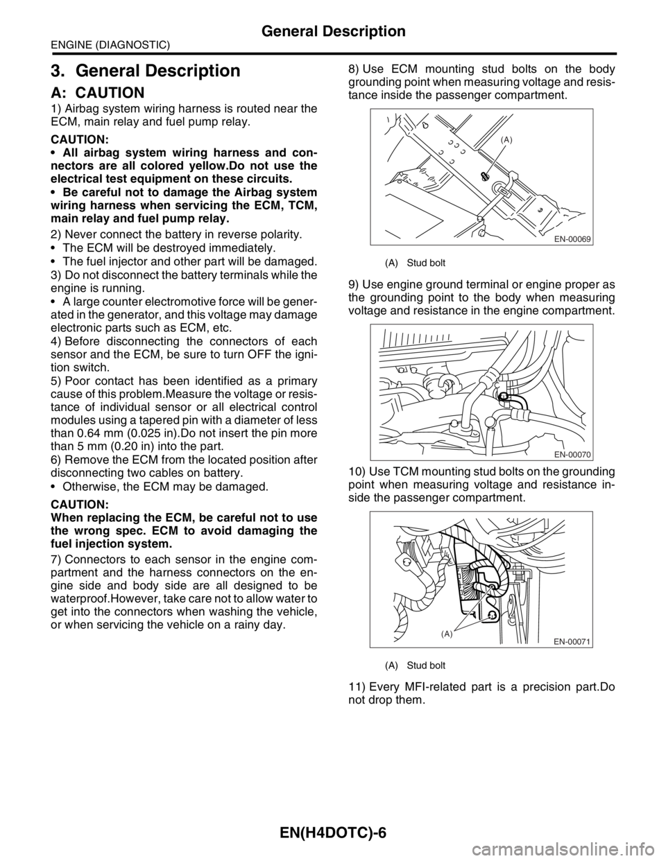
or when servicing the vehicle on a rainy day. 8) Use ECM mounting stud bolts on the body
grounding point when measuring voltage and resis-
tance inside the passenger compartment.
9) Use engine ground terminal or engine proper as
the grounding point to the body when measuring
voltage and resistance in the engine compartment.
10) Use TCM mounting stud bolts on the grounding
point when measuring voltage and resistance in-
side the passenger compartment.
11) Every MFI-related part is a precision part.Do
not drop them.
(A) Stud bolt
(A) Stud bolt
EN-00069
(A)
EN-00070
EN-00071(A)