Page 799 of 2870
FU(H4SO)-17
FUEL INJECTION (FUEL SYSTEM)
Intake Manifold
2) Connect the fuel hoses.
3) Connect the EGR pipe to intake manifold.
Tightening torque:
34 N
⋅m (3.4 kgf-m, 24.6 ft-lb)
4) Connect the connector to the camshaft position
sensor.
5) Connect the connector to the oil pressure switch.6) Connect the connector to the crankshaft position
sensor.
7) Connect the knock sensor connector.
8) Connect the connectors to the engine coolant
temperature sensor.
9) Install the air cleaner case stay RH and engine
harness bracket, and connect the engine harness
connectors to the bulkhead connectors.
(A) Fuel delivery hose
(B) Fuel return hose
(C) Evaporation hose
(B) (A)
(C)
FU-00259
FU-00148
FU-00147
FU-00146
FU-00056
FU-00062
FU-00145
FU-00258
Page 807 of 2870
FU(H4SO)-25
FUEL INJECTION (FUEL SYSTEM)
Engine Coolant Temperature Sensor
4. Engine Coolant Temperature
Sensor
A: REMOVAL
1) Disconnect the ground cable from battery.
2) Remove the air intake duct and air cleaner as-
sembly.
take Duct.>
Cleaner Case.>
3) Disconnect the connector from the engine cool-
ant temperature sensor.
4) Remove the engine coolant temperature sensor.
B: INSTALLATION
Install in the reverse order of removal.
Tightening torque:
18 N
⋅m (1.8 kgf-m, 13.0 ft-lb)
FU-00009
FU-00145
FU-00288
Page 808 of 2870
FU(H4SO)-26
FUEL INJECTION (FUEL SYSTEM)
Crankshaft Position Sensor
5. Crankshaft Position Sensor
A: REMOVAL
1) Disconnect the ground cable from battery.
2) Remove the bolt which install crankshaft position
sensor to the cylinder block.
3) Remove the crankshaft position sensor, and dis-
connect the connector from it.
B: INSTALLATION
Install in the reverse order of removal.
Tightening torque:
T: 6.4 N
⋅m (0.65 kgf-m, 4.7 ft-lb)
FU-00009
FU-00056
FU-00057
FU-00058
T
Page 809 of 2870
FU(H4SO)-27
FUEL INJECTION (FUEL SYSTEM)
Camshaft Position Sensor
6. Camshaft Position Sensor
A: REMOVAL
1) Disconnect the ground cable from battery.
2) Disconnect the connector from the camshaft po-
sition sensor.
3) Remove the bolt which installs camshaft position
sensor to the camshaft position sensor support.
4) Remove the bolt which installs camshaft position
sensor support to the camshaft cap LH.
5) Remove the camshaft position sensor and cam-
shaft position sensor support as a unit.6) Remove the camshaft position sensor itself.
B: INSTALLATION
Install in the reverse order of removal.
Tightening torque:
Camshaft position sensor support;
6.4 N
⋅m (0.65 kgf-m, 4.7 ft-lb)
Camshaft position sensor;
6.4 N
⋅m (0.65 kgf-m, 4.7 ft-lb)
FU-00009
FU-00147
FU-00177
FU-00178
FU-00179
Page 810 of 2870
FU(H4SO)-28
FUEL INJECTION (FUEL SYSTEM)
Knock Sensor
7. Knock Sensor
A: REMOVAL
1) Disconnect the ground cable from battery.
2) Remove the air cleaner case.
IN(H4SO)-6, REMOVAL, Air Cleaner Case.>
3) Disconnect the knock sensor connector.
4) Remove the knock sensor from the cylinder
block.
B: INSTALLATION
1) Install the knock sensor to the cylinder block.
Tightening torque:
24 N
⋅m (2.4 kgf-m, 17.4 ft-lb)
NOTE:
The extraction area of the knock sensor cord must
be positioned at a 60° angle relative to the engine
rear.
2) Connect the knock sensor connector.
3) Install the air cleaner case.
Case.>
4) Connect the battery ground cable to battery.
FU-00009
FU-00062
FU-00519
(A) Front side
FU-00413
(A)
60
FU-00062
FU-00009
Page 811 of 2870

FU(H4SO)-29
FUEL INJECTION (FUEL SYSTEM)
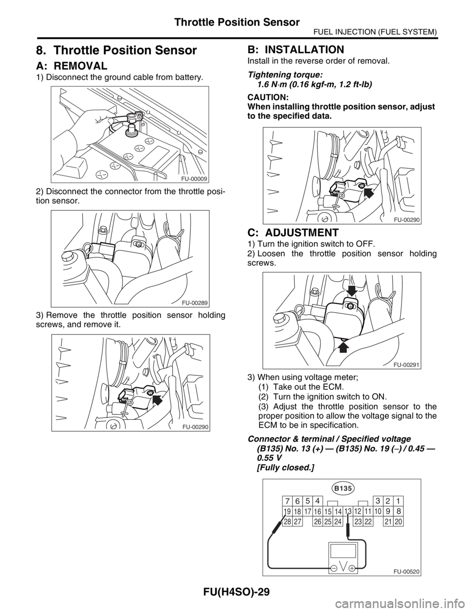
Throttle Position Sensor
8. Throttle Position Sensor
A: REMOVAL
1) Disconnect the ground cable from battery.
2) Disconnect the connector from the throttle posi-
tion sensor.
3) Remove the throttle position sensor holding
screws, and remove it.
B: INSTALLATION
Install in the reverse order of removal.
Tightening torque:
1.6 N
⋅m (0.16 kgf-m, 1.2 ft-lb)
CAUTION:
When installing throttle position sensor, adjust
to the specified data.
C: ADJUSTMENT
1) Turn the ignition switch to OFF.
2) Loosen the throttle position sensor holding
screws.
3) When using voltage meter;
(1) Take out the ECM.
(2) Turn the ignition switch to ON.
(3) Adjust the throttle position sensor to the
proper position to allow the voltage signal to the
ECM to be in specification.
Connector & terminal / Specified voltage
(B135) No. 13 (+) — (B135) No. 19 (
−) / 0.45 —
0.55 V
[Fully closed.]
FU-00009
FU-00289
FU-00290
FU-00290
FU-00291
FU-00520
4
1 526
18 1516
7
891011
17
19
20121314
B135
3
2122232425262728
Page 812 of 2870

FU(H4SO)-30
FUEL INJECTION (FUEL SYSTEM)
Throttle Position Sensor
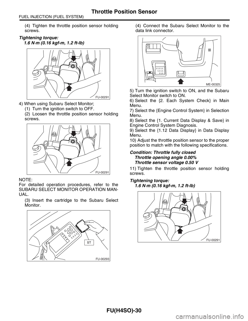
(4) Tighten the throttle position sensor holding
screws.
Tightening torque:
1.6 N
⋅m (0.16 kgf-m, 1.2 ft-lb)
4) When using Subaru Select Monitor;
(1) Turn the ignition switch to OFF.
(2) Loosen the throttle position sensor holding
screws.
NOTE:
For detailed operation procedures, refer to the
SUBARU SELECT MONITOR OPERATION MAN-
UAL.
(3) Insert the cartridge to the Subaru Select
Monitor.(4) Connect the Subaru Select Monitor to the
data link connector.
5) Turn the ignition switch to ON, and the Subaru
Select Monitor switch to ON.
6) Select the {2. Each System Check} in Main
Menu.
7) Select the {Engine Control System} in Selection
Menu.
8) Select the {1. Current Data Display & Save} in
Engine Control System Diagnosis.
9) Select the {1.12 Data Display} in Data Display
Menu.
10) Adjust the throttle position sensor to the proper
position to match with the following specifications.
Condition: Throttle fully closed
Throttle opening angle 0.00%
Throttle sensor voltage 0.50 V
11) Tighten the throttle position sensor holding
screws.
Tightening torque:
1.6 N
⋅m (0.16 kgf-m, 1.2 ft-lb)
FU-00291
FU-00291
FU-00293
ST
ME-00325
FU-00291
Page 813 of 2870
FU(H4SO)-31
FUEL INJECTION (FUEL SYSTEM)
Manifold Absolute Pressure Sensor
9. Manifold Absolute Pressure
Sensor
A: REMOVAL
1) Disconnect the ground cable from battery.
2) Disconnect the connector from the manifold ab-
solute pressure sensor.
3) Remove the manifold absolute pressure sensor.
B: INSTALLATION
Install in the reverse order of removal.
Tightening torque:
1.6 N
⋅m (0.16 kgf-m, 1.2 ft-lb)
NOTE:
Replace the O-ring with a new one.
FU-00009
FU-00294
FU-00295
FU-00295
FU-00296