Page 401 of 2870
IDI-17
INSTRUMENTATION/DRIVER INFO
Ambient Sensor
8. Ambient Sensor
A: REMOVAL
1) Disconnect the ground cable from battery.
2) Disconnect the ambient sensor connector.
3) Remove the ambient sensor (A) from radiator lower
panel.
B: INSTALLATION
Install in the reverse order of removal.
C: INSPECTION
Measure the ambient sensor resistance.
If NG, replace the ambient sensor.
Terminal Resistance
1 and 2 3 kΩ/25°C (77°F)
IDI00008
(A)
IDI-00009
21
Page 402 of 2870
IDI-18
INSTRUMENTATION/DRIVER INFO
Ambient Sensor
Page 516 of 2870

EI-40
EXTERIOR/INTERIOR TRIM
Instrument Panel Assembly
16.Instrument Panel Assembly
A: REMOVAL
CAUTION:
All airbag system wiring harness and connec-
tors are colored yellow. Do not use electrical test
equipment on these circuits.
Be careful not to damage the airbag system
harness when servicing the instrument panel.
1. REMOVAL OF INSTRUMENT PANEL
ONLY
1) Disconnect the ground cable from battery.
2) Loosen the screws and clips, and then remove
the lower cover.
3) Disconnect the in-vehicle sensor hose and con-
nector.
4) Remove the console front cover and console
cover.
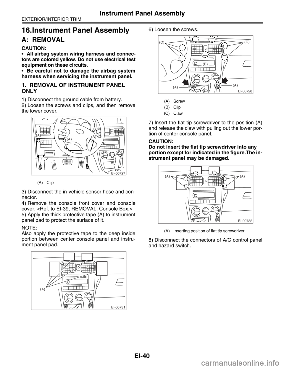
5) Apply the thick protective tape (A) to instrument
panel pad to protect the surface of it.
NOTE:
Also apply the protective tape to the deep inside
portion between center console panel and instru-
ment panel pad.6) Loosen the screws.
7) Insert the flat tip screwdriver to the position (A)
and release the claw with pulling out the lower por-
tion of center console panel.
CAUTION:
Do not insert the flat tip screwdriver into any
portion except for indicated in the figure.The in-
strument panel may be damaged.
8) Disconnect the connectors of A/C control panel
and hazard switch.
(A) Clip
EI-00727
(A)
(A)(A)
EI-00731
(A)
(A) Screw
(B) Clip
(C) Claw
(A) Inserting position of flat tip screwdriver
EI-00728
(C)
(A)(A)(C)
(B)
EI-00732
(A) (A)
Page 576 of 2870

CC(H4SO)-8
CRUISE CONTROL SYSTEM (DIAGNOSTIC)
Cruise Control Module I/O Signal
B: WIRING DIAGRAM
Brake switch/Clutch switch
(MT model)16 Leave clutch pedal released (MT model), while cruise control main switch is
turned ON.
Then check that;
Battery voltage is present when brake pedal is released.
“0” volt is present when brake pedal is depressed.
Additionally only in MT model, keep the cruise control main switch to ON and
leave brake pedal released.
Then check that;
Battery voltage is present when clutch pedal is released.
“0” volt is present when clutch pedal is depressed.
Data link connector 17 —
Data link connector 18 —
Vehicle speed sensor (MT
model)
TCM (AT model)19 Lift-up the vehicle until all four wheels are raised off ground, and then rotate any
wheel manually.
Approx. “5” and “0” volt pulse signals are alternately input to cruise control mod-
ule.
Stop light switch 20 Turn ignition switch to OFF.
Then check that;
Battery voltage is present when brake pedal is depressed.
“0” volt is present when brake pedal is released.
NOTE:
Voltage at terminals 5, 7, 13 and 14 cannot be checked unless vehicle is driving by cruise control operation.Content Terminal No. Measuring conditions and I/O signals (ignition switch ON and engine idling)
Page 577 of 2870

CC(H4SO)-9
CRUISE CONTROL SYSTEM (DIAGNOSTIC)
Subaru Select Monitor
5. Subaru Select Monitor
A: OPERATION
1. GENERAL
The on-board diagnosis function of the cruise control
system uses an external Subaru Select Monitor.
The on-board diagnosis function operates in two cat-
egories, which are used depending on the type of
problems;
1) Cruise cancel conditions diagnosis:
(1) This category of diagnosis requires actual
vehicle driving in order to determine the cause,
(as when cruise speed is cancelled during driv-
ing although cruise cancel condition is not en-
tered).
(2) Cruise control module memory stores the
cancel condition (Code No.) which occurred dur-
ing driving. When there are plural cancel condi-
tions (Code No.), they are shown on the Subaru
Select Monitor.
CAUTION:
The cruise control memory stores not only the
cruise “cancel” which occurred (although “can-
cel” operation is not entered by the driver), but
also the “cancel” condition input by the driver.
The content of memory is cleared when igni-
tion switch or cruise main switch is turned OFF.
2) Real-time diagnosis:
The real-time diagnosis function is used to deter-
mine whether or not the input signal system is in
good order, according to signal emitted from
switches, sensors, etc.
(1) Vehicle cannot be driven at cruise speed be-
cause problem occurs in the cruise control sys-
tem or its associated circuits.
(2) Monitor the signal conditions from switches
and sensors.
2. CRUISE CANCEL CONDITIONS DIAG-
NOSIS
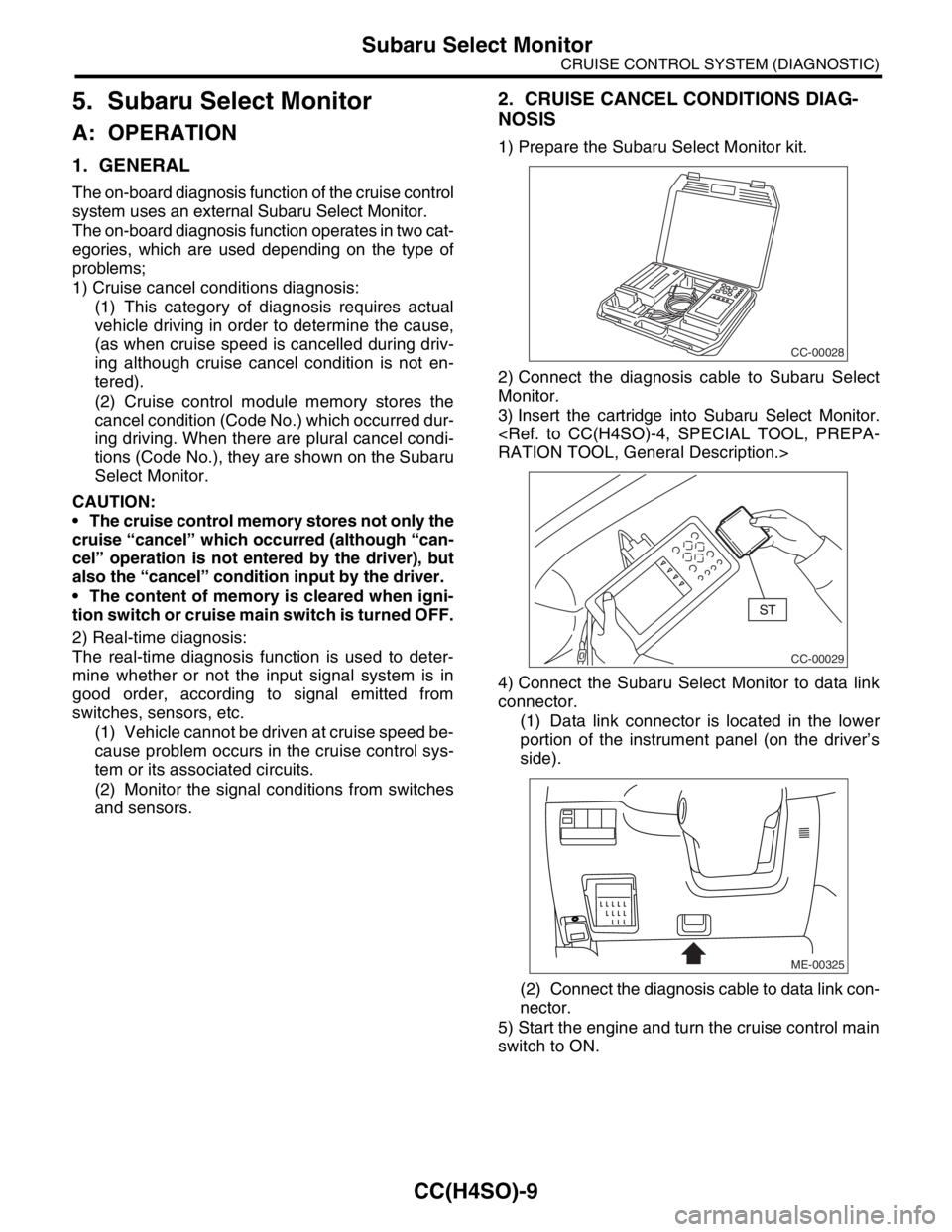
1) Prepare the Subaru Select Monitor kit.
2) Connect the diagnosis cable to Subaru Select
Monitor.
3) Insert the cartridge into Subaru Select Monitor.
RATION TOOL, General Description.>
4) Connect the Subaru Select Monitor to data link
connector.
(1) Data link connector is located in the lower
portion of the instrument panel (on the driver’s
side).
(2) Connect the diagnosis cable to data link con-
nector.
5) Start the engine and turn the cruise control main
switch to ON.
CC-00028
CC-00029
ME-00325
Page 579 of 2870

CC(H4SO)-11
CRUISE CONTROL SYSTEM (DIAGNOSTIC)
Diagnostic Procedure with Symptom
6. Diagnostic Procedure with Symptom
A: SYMPTOM CHART
Symptom Repair area Reference
1Cruise control main switch is
not turned ON. (1) Check the power supply.
nostic Procedure with Symptom.>
(2) Check the cruise control
main switch.
MAIN SWITCH, Diagnostic Procedure with Symptom.>
2Cruise indicator light does not
illuminate.Check the cruise indicator
light.
LIGHT, Diagnostic Procedure with Symptom.>
3Cruise control cannot be set. (1) Check the SET/COAST
switch.
COMMAND SWITCH, Diagnostic Procedure with Symp-
tom.>
(2) Check the stop light switch
and brake switch.
AND BRAKE SWITCH, Diagnostic Procedure with Symp-
tom.>
(3) Check the clutch switch
(MT model).
MODEL), Diagnostic Procedure with Symptom.>
(4) Check the inhibitor switch
(AT model).
(AT MODEL), Diagnostic Procedure with Symptom.>
(5) Check the vehicle speed
sensor.
SOR, Diagnostic Procedure with Diagnostic Trouble
Code (DTC).>
(6) Check the motor drive
system.
MOTOR, Diagnostic Procedure with Diagnostic Trouble
Code (DTC).>
(7) Check the motor clutch
drive system.
CLUTCH, Diagnostic Procedure with Diagnostic Trouble
Code (DTC).>
4Vehicle speed is not held
within set speed ±3 km/h (±2
MPH). (1) Check the vehicle speed
sensor.
SOR, Diagnostic Procedure with Diagnostic Trouble
Code (DTC).>
(2) Check the motor drive
system.
MOTOR, Diagnostic Procedure with Diagnostic Trouble
Code (DTC).>
(3) Check the motor clutch
drive system.
CLUTCH, Diagnostic Procedure with Diagnostic Trouble
Code (DTC).>
5Vehicle speed does not
increase or does not return to
set speed after RESUME/
ACCEL switch has been
pressed.(1) Check the RESUME/
AC CEL switch.
COMMAND SWITCH, Diagnostic Procedure with Symp-
tom.>
(2) Check the motor drive
system.
MOTOR, Diagnostic Procedure with Diagnostic Trouble
Code (DTC).>
(3) Check the motor clutch
drive system.
CLUTCH, Diagnostic Procedure with Diagnostic Trouble
Code (DTC).>
6Vehicle speed does not
decrease after SET/COAST
switch has been pressed. (1) Check the SET/COAST
switch.
COMMAND SWITCH, Diagnostic Procedure with Symp-
tom.>
(2) Check the motor drive
system.
MOTOR, Diagnostic Procedure with Diagnostic Trouble
Code (DTC).>
(3) Check the motor clutch
drive system.
CLUTCH, Diagnostic Procedure with Diagnostic Trouble
Code (DTC).>
Page 595 of 2870

CC(H4SO)-27
CRUISE CONTROL SYSTEM (DIAGNOSTIC)
List of Diagnostic Trouble Code (DTC)
7. List of Diagnostic Trouble Code (DTC)
A: LIST
DTC Item Contents of diagnosis Reference
21 Inner relay is seized. Cruise control module inner relay is seized when main
switch is OFF.
DTC 21, 24, 25 AND 2A
CRUISE CONTROL
MODULE BUILT-IN
RELAY, CPU RAM, Diag-
nostic Procedure with
Diagnostic Trouble Code
(DTC).>
22 Vehicle speed sensor Vehicle speed signal changes more than 10 km/h (6
MPH) within 350 ms.
DTC 22 VEHICLE SPEED
SENSOR, Diagnostic Pro-
cedure with Diagnostic
Trouble Code (DTC).>
24 Cruise control module is
abnormal.Two vehicle speed values stored in cruise control module
memory are not the same.
DTC 21, 24, 25 AND 2A
CRUISE CONTROL
MODULE BUILT-IN
RELAY, CPU RAM, Diag-
nostic Procedure with
Diagnostic Trouble Code
(DTC).>
25 Cruise control module is
abnormal.Two output values stored in cruise control module mem-
ory are not the same.
DTC 21, 24, 25 AND 2A
CRUISE CONTROL
MODULE BUILT-IN
RELAY, CPU RAM, Diag-
nostic Procedure with
Diagnostic Trouble Code
(DTC).>
28 Wiring harness opened. Open wiring harness circuit is detected via control mod-
ule relay when main switch is ON.
DTC 28 WIRING HAR-
NESS OPENED., Diag-
nostic Procedure with
Diagnostic Trouble Code
(DTC).>
35 Motor drive system is
abnormal. Motor output circuit is open or shorted.
Motor drive circuit is open or shorted.
DTC 35 AND 36 ACTUA-
TOR MOTOR, Diagnostic
Procedure with Diagnos-
tic Trouble Code (DTC).>
36 Trouble of motor turning
speedMotor turning speed is low.
DTC 35 AND 36 ACTUA-
TOR MOTOR, Diagnostic
Procedure with Diagnos-
tic Trouble Code (DTC).>
37 Motor clutch drive system
is abnormal. Motor clutch output circuit is open or shorted.
Motor clutch drive circuit is open or shorted.
DTC 37 ACTUATOR
MOTOR CLUTCH, Diag-
nostic Procedure with
Diagnostic Trouble Code
(DTC).>
Page 598 of 2870
CC(H4SO)-30
CRUISE CONTROL SYSTEM (DIAGNOSTIC)
Diagnostic Procedure with Diagnostic Trouble Code (DTC)
B: DTC 22 VEHICLE SPEED SENSOR
DIAGNOSIS:
Disconnection or short circuit of vehicle speed sensor system.
TROUBLE SYMPTOM:
Cruise control cannot be set. (Cancelled immediately.)
WIRING DIAGRAM:
CC-00042
BATTERY
CRUISE
CONTROL
MODULE
M/B No.5IGNITION
RELAY
B17 TCM
E
C17
B17
B21
B94E2
B56
B56 C:
GEVEHICLE SPEED
SENSOR
(MT MODEL) 1
2
3
619
B94
E
16
MT
AT : AT MODEL C:
MT : MT MODELAT
12312345678910
11 12 13 14 15 16 17 18 19 20
123
4
56
78
9
1011 12
1314 15 16
12
789 56 3410 11 12
19 20 2113 14 15 16 17 18
22
23
24
F60
E216
B100
F29
LT
LT
XLXL
LT : LHD TURBO
MODEL
XL : EXCEPT LHD
TURBO MODEL
: TURBO MODEL
: NON-TURBO
MODELXL
LT
TB
NA
B17
3412
F2
1234 5678910 11 12 13 14 15 16 17 18 19 20
NA
TB :
:
F60LT :
B21XL :