2004 SUBARU FORESTER sensor
[x] Cancel search: sensorPage 599 of 2870

CC(H4SO)-31
CRUISE CONTROL SYSTEM (DIAGNOSTIC)
Diagnostic Procedure with Diagnostic Trouble Code (DTC)
Step Check Yes No
1 CHECK TRANSMISSION TYPE.Is the target MT model? Go to step 2.Go to step 6.
2 CHECK HARNESS BETWEEN BATTERY
AND VEHICLE SPEED SENSOR.
1) Turn the ignition switch to OFF.
2) Disconnect the harness connector from
vehicle speed sensor.
3) Turn the ignition switch to ON.
4) Measure the voltage between vehicle
speed sensor harness connector terminal and
chassis ground.
Connector & terminal
(B17) No. 3 (+) — Chassis ground (
−):Is the voltage more than 10 V? Go to step 3.Check the harness
for open or short
between fuse relay
and vehicle speed
sensor.
3 CHECK HARNESS BETWEEN CRUISE CON-
TROL MODULE AND VEHICLE SPEED SEN-
SOR.
1) Turn the ignition switch to OFF.
2) Disconnect the harness connector from
cruise control module.
3) Measure the resistance between vehicle
speed sensor harness connector terminal and
cruise control module harness connector ter-
minal.
Connector & terminal
(B17) No. 1 — (B94) No. 19:Is the resistance less than 10
Ω?Go to step 4.Repair the har-
ness.
4 CHECK HARNESS BETWEEN VEHICLE
SPEED SENSOR AND ENGINE GROUND.
1) Turn the ignition switch to OFF.
2) Measure the resistance between vehicle
speed sensor harness connector terminal and
engine ground.
Connector & terminal
(B17) No. 2 — Engine ground:Is the resistance less than 10
Ω?Go to step 5.Repair the har-
ness.
5 CHECK VEHICLE SPEED SENSOR.
1) Connect the harness connector to vehicle
speed sensor.
2) Lift-up the vehicle and support with rigid
racks.
3) Drive the vehicle at speed greater than 20
km/h (12 MPH).
Warning:
Be careful not to be caught up by the run-
ning wheels.
4) Measure the voltage between cruise control
module harness connector terminal and chas-
sis ground.
Connector & terminal
(B94) No. 19 (+) — Chassis ground (
−):Is the voltage less than 0 V ←
→ more than 5 V?Replace the cruise
control module.
Module.>Replace the vehi-
cle speed sensor.
6 CHECK HARNESS BETWEEN CRUISE CON-
TROL MODULE AND TCM.
1) Turn the ignition switch to OFF.
2) Disconnect the harness connector from
TCM and cruise control module.
3) Measure the resistance between cruise
control module harness connector terminal
and TCM harness connector terminal.
Connector & terminal
(B94) No. 19 — (B56) No. 17:Is the resistance less than 10
Ω?Go to step 7.Repair the har-
ness.
Page 620 of 2870

CC(H4DOTC 2.5)-8
CRUISE CONTROL SYSTEM (DIAGNOSTIC)
Subaru Select Monitor
5. Subaru Select Monitor
A: OPERATION
1. GENERAL
The on-board diagnosis function of the cruise con-
trol system uses the Subaru Select Monitor.
The on-board diagnosis function operates in two
categories, which are used depending on the type
of problems;
1) Cruise cancel conditions diagnosis:
(1) This category of diagnosis requires actual ve-
hicle driving in order to determine the cause, (as
when cruise speed is cancelled during driving al-
though cruise cancel condition is not entered).
(2) Cruise control memory of ECM stores the
cancel condition (Code No.) which occurred dur-
ing driving. When there are plural cancel condi-
tions (Code No.), they are shown on the Subaru
Select Monitor.
CAUTION:
The cruise control memory stores not only the
cruise “cancel” which occurred (although “can-
cel” operation is not entered by the driver), but
also the “cancel” condition input by the driver.
The content of memory is cleared when igni-
tion switch or cruise main switch is turned OFF.
2) Real-time diagnosis:
The real-time diagnosis function is used to deter-
mine whether or not the input signal system is in
good order, according to signal emitted from
switches, sensors, etc.
(1) Vehicle cannot be driven at cruise speed be-
cause problem occurs in the cruise control sys-
tem or its associated circuits.
(2) Monitor the signal conditions from switches
and sensors.
2. CRUISE CANCEL CONDITIONS DIAG-
NOSIS
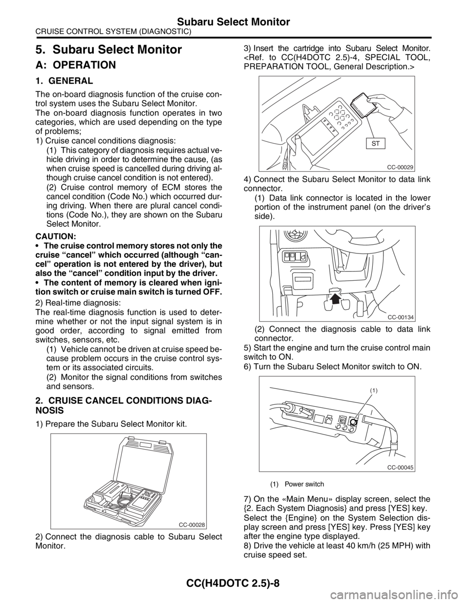
1) Prepare the Subaru Select Monitor kit.
2) Connect the diagnosis cable to Subaru Select
Monitor.3) Insert the cartridge into Subaru Select Monitor.
4) Connect the Subaru Select Monitor to data link
connector.
(1) Data link connector is located in the lower
portion of the instrument panel (on the driver’s
side).
(2) Connect the diagnosis cable to data link
connector.
5) Start the engine and turn the cruise control main
switch to ON.
6) Turn the Subaru Select Monitor switch to ON.
7) On the «Main Menu» display screen, select the
{2. Each System Diagnosis} and press [YES] key.
Select the {Engine} on the System Selection dis-
play screen and press [YES] key. Press [YES] key
after the engine type displayed.
8) Drive the vehicle at least 40 km/h (25 MPH) with
cruise speed set.
CC-00028
(1) Power switch
CC-00029
CC-00134
CC-00045
(1)
Page 622 of 2870

CC(H4DOTC 2.5)-10
CRUISE CONTROL SYSTEM (DIAGNOSTIC)
Diagnostic Procedure with Symptom
6. Diagnostic Procedure with Symptom
A: SYMPTOM CHART
Symptom Repair area Reference
1Cruise control main switch is
not turned to ON. (Cruise
indicator light does not illumi-
nate)(1) Check the cruise indicator
light.
(2) Check the cruise control
command switch.
Procedure with Diagnostic Trouble Code (DTC).>
2 Cruise control cannot be set. (1) Check the cruise control
command switch
Procedure with Diagnostic Trouble Code (DTC).>
(2) Check the stop light switch
and brake switch.
cedure with Diagnostic Trouble Code (DTC).>
(3) Check the clutch switch.
Code (DTC).>
(4) Check the neutral switch.
Trouble Code (DTC).>
(5) Check the vehicle speed
sensor.
Trouble Code (DTC).>
3Vehicle speed is not held
within set speed ±3 km/h (±2
MPH). Check the vehicle speed sen-
sor.
Trouble Code (DTC).>
4Vehicle speed does not
increase or does not return to
set speed after RESUME/
ACCEL switch has been
pressed.Check the RESUME/ACCEL
switch.
Procedure with Diagnostic Trouble Code (DTC).>
5Vehicle speed does not
decrease after SET/COAST
switch has been pressed. Check the SET/COAST
switch.
Procedure with Diagnostic Trouble Code (DTC).>
6Cruise control is not released
after CANCEL switch has
been pressed.Check the CANCEL switch.
Procedure with Diagnostic Trouble Code (DTC).>
7Cruise control is not released
after the brake pedal has
been depressed. Check the stop light switch
and brake switch.
cedure with Diagnostic Trouble Code (DTC).>
8Cruise control is not released
after the clutch pedal has
been depressed.Check the clutch switch.
Code (DTC).>
9Cruise control is not released
after shifting to neutral posi-
tion.Check the neutral switch.
Trouble Code (DTC).>
Page 626 of 2870

CC(H4DOTC 2.5)-14
CRUISE CONTROL SYSTEM (DIAGNOSTIC)
List of Diagnostic Trouble Code (DTC)
21 Cruise control switch is
abnormal when the igni-
tion switch is turned to ON.Each switch of cruise control command switch has
already been ON when the ignition switch is turned to
ON.This DTC is indicated
without operating the main
switch.
DTC 11, 15, 21 AND 24
CRUISE CONTROL
COMMAND SWITCH,
Diagnostic Procedure with
Diagnostic Trouble Code
(DTC).>
22 Vehicle speed variation is
abnormal.Abnormality of vehicle speed variation is detected.
VEHICLE SPEED SEN-
SOR, Diagnostic Proce-
dure with Diagnostic
Trouble Code (DTC).>
23 Engine-related sensor is
abnormal.Abnormality related to engine is detected.
Procedure.>
24 Cruise control-related
switch is abnormal.Abnormality of command switch is detected. (Open cir-
cuit is detected when continuing to be ON for an
extremely long time [approx. two minutes].)This DTC is indicated with
normal operation.
DTC 11, 15, 21 AND 24
CRUISE CONTROL
COMMAND SWITCH,
Diagnostic Procedure with
Diagnostic Trouble Code
(DTC).>
25 Brake switch input circuit
is abnormal.Abnormality of brake switch input circuit in ECM is
detected.
STOP LIGHT SWITCH
AND BRAKE SWITCH,
Diagnostic Procedure with
Diagnostic Trouble Code
(DTC).>
26 Engine speed signal. Abnormal increase of engine speed is detected.
Gear is shifted to neutral, 1st or reverse position.Cruise with more than 2nd
shift position.
32 Out of vehicle speed range
of cruise control operation. Vehicle speed becomes under the control limit during
cruise driving.
Set operation is conducted out of vehicle speed range
for setting
RESUME operation is conducted without vehicle
speed memory.This DTC is also indicated
when increasing the
speed to the cruise set
available vehicle speed
and conducting the set
operation again.
DTC 22 AND 32 VEHICLE
SPEED SENSOR, Diag-
nostic Procedure with
Diagnostic Trouble Code
(DTC).>
33 Prohibition of WAIT after
acceleration operation.Vehicle speed becomes over the control limit during
cruise driving.This DTC is indicated
when running at the high
speed which is not suit-
able for cruise control. In
this case, conduct the
cruise set operation again
after decreasing the
speed to the cruise set
available vehicle speed. DTC Item Contents of diagnosis Reference
Page 638 of 2870

CC(H4DOTC 2.5)-26
CRUISE CONTROL SYSTEM (DIAGNOSTIC)
Diagnostic Procedure with Diagnostic Trouble Code (DTC)
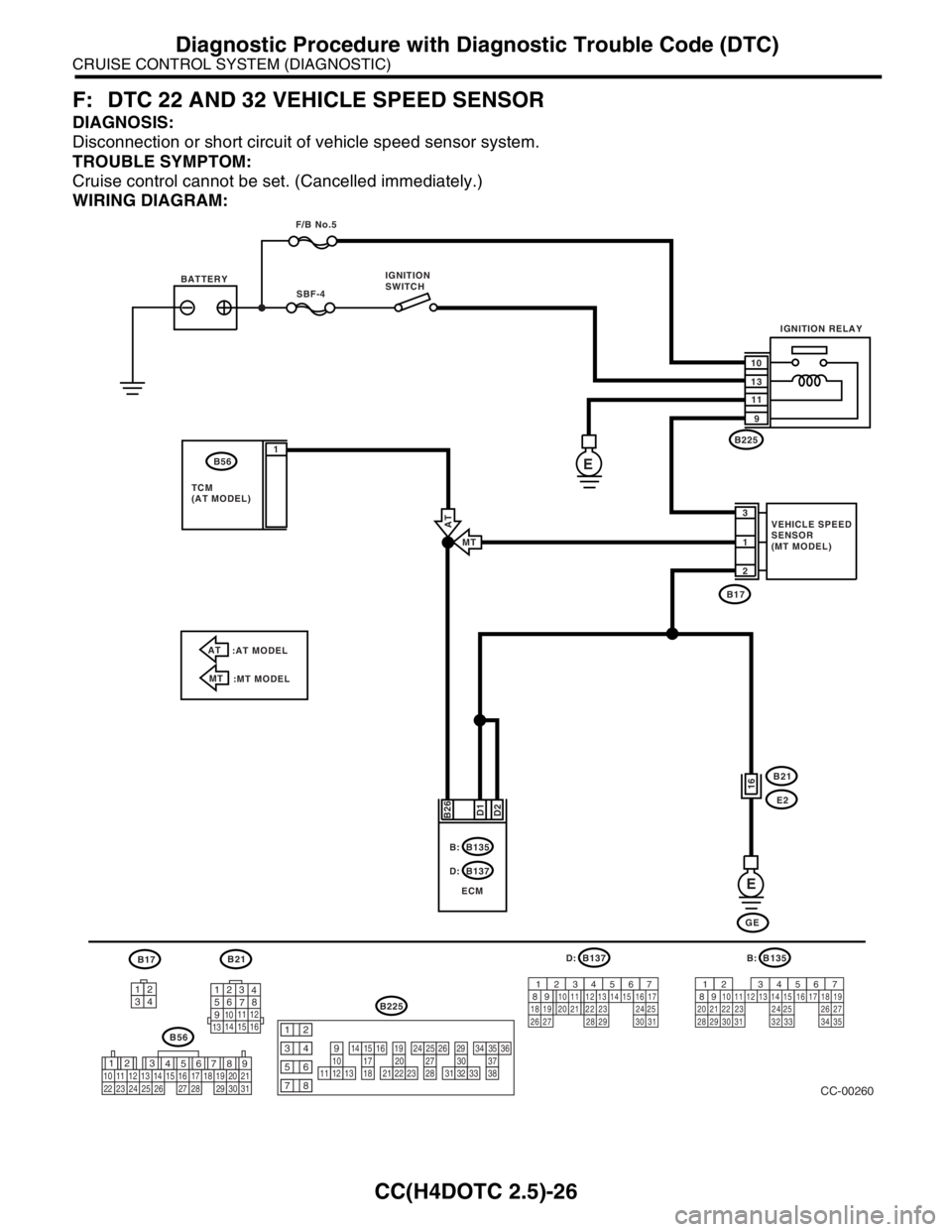
F: DTC 22 AND 32 VEHICLE SPEED SENSOR
DIAGNOSIS:
Disconnection or short circuit of vehicle speed sensor system.
TROUBLE SYMPTOM:
Cruise control cannot be set. (Cancelled immediately.)
WIRING DIAGRAM:
3412
12
789 56 3
410 11 1219 20 21
29 30 31 13
14 151617
27 2818
22 23 24 25 2610111213
1415161718
1920212223
2425262728
2930313233
3435363738
12
934
56
78
B21
123
4
56
78
9
1011 12
1314 15 16
B17B137
9
30
29 283120 19 18
22
211012
1114
24
27 26
17 16123456713
2315
258D:
B56
B225
B135
9
30
29 28312019 18
22 2110
12 1114
2427 2617 16123456713
2315
258B:
32 3334 35
CC-00260
SBF-4
B171
2 3
D2 B26
E
B21
E2
GE B137
ECM D:B135 B: BATTERYIGNITION
SWITCH
VEHICLE SPEED
SENSOR
(MT MODEL) F/B No.5
IGNITION RELAY
10
13
11
9
D1
16
E
B225
B56
TCM
(AT MODEL)1
AT
:AT MODEL
MT
:MT MODELMT
AT
Page 639 of 2870

CC(H4DOTC 2.5)-27
CRUISE CONTROL SYSTEM (DIAGNOSTIC)
Diagnostic Procedure with Diagnostic Trouble Code (DTC)
Step Check Yes No
1 CHECK TRANSMISSION TYPE.Is the target MT model? Go to step 2.Go to step 6.
2 CHECK HARNESS BETWEEN BATTERY
AND VEHICLE SPEED SENSOR.
1) Turn the ignition switch to OFF.
2) Disconnect the harness connector from
vehicle speed sensor.
3) Turn the ignition switch to ON.
4) Measure the voltage between vehicle
speed sensor harness connector terminal and
chassis ground.
Connector & terminal
(B17) No. 3 (+) — Chassis ground (
−):Is the voltage more than 10 V? Go to step 3.Check the harness
for open or short
between fuse and
vehicle speed sen-
sor.
3 CHECK HARNESS BETWEEN ECM AND VE-
HICLE SPEED SENSOR.
1) Turn the ignition switch to OFF.
2) Disconnect the harness connector from
ECM.
3) Measure the resistance between vehicle
speed sensor harness connector terminal and
ECM harness connector terminal.
Connector & terminal
(B17) No. 1 — (B135) No. 26:Is the resistance less than 10
Ω?Go to step 4.Repair the har-
ness.
4 CHECK HARNESS BETWEEN VEHICLE
SPEED SENSOR AND ENGINE GROUND.
1) Turn the ignition switch to OFF.
2) Measure the resistance between vehicle
speed sensor harness connector terminal and
engine ground.
Connector & terminal
(B17) No. 2 — Engine ground:Is the resistance less than 10
Ω?Go to step 5.Repair the har-
ness.
5 CHECK VEHICLE SPEED SENSOR.
1) Connect the harness connector to vehicle
speed sensor.
2) Lift-up the vehicle and support with rigid
racks.
3) Drive the vehicle at speed greater than 20
km/h (12 MPH).
Warning:
Be careful not to be caught up by the run-
ning wheels.
4) Measure the voltage between ECM har-
ness connector terminal and chassis ground.
Connector & terminal
(B135) No. 26 (+) — Chassis ground (
−):Is the voltage 1 V ← → 5 V? Check the poor
contact of ECM
connector.Replace the vehi-
cle speed sensor.
6 CHECK HARNESS BETWEEN ECM AND
TCM.
1) Turn the ignition switch to OFF.
2) Disconnect the harness connector from
ECM and TCM.
3) Measure the resistance between ECM har-
ness connector terminal and TCM harness
connector terminal.
Connector & terminal
(B135) No. 26 — (B56) No. 1:Is the resistance less than 10
Ω?Go to step 7.Repair the har-
ness.
Page 677 of 2870

TC-12
TRANSFER CASE
Transfer Duty Solenoid and Valve Body
11.Transfer Duty Solenoid and
Valve Body
A: NOTE
For removal, installation and inspection work, refer
to “4AT” section.
Page 720 of 2870

RM-5
RECOMMENDED MATERIAL
Recommended Materials
4. FLUID
Use the fluids specified in the table below. Do not mix two different kinds or makes of fluid.
5. COOLANT
Use genuine coolant to protect the engine.
6. REFRIGERANT
Standard air conditioners on Subaru vehicles use HFC134a refrigerant. Do not mix it with other refrigerants.
Also, do not use any air compressor oil except for ZXL200PG.
7. GREASE
Use the grease and supplementary lubricants shown in the table below.
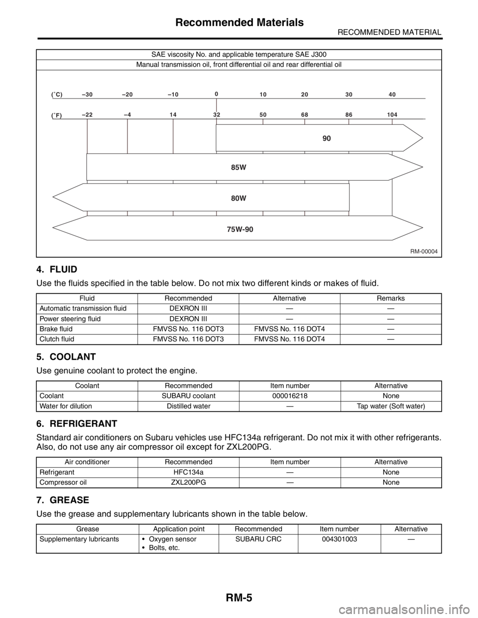
SAE viscosity No. and applicable temperature SAE J300
Manual transmission oil, front differential oil and rear differential oil
Fluid Recommended Alternative Remarks
Automatic transmission fluid DEXRON III — —
Power steering fluid DEXRON III — —
Brake fluid FMVSS No. 116 DOT3 FMVSS No. 116 DOT4 —
Clutch fluid FMVSS No. 116 DOT3 FMVSS No. 116 DOT4 —
Coolant Recommended Item number Alternative
Coolant SUBARU coolant 000016218 None
Water for dilution Distilled water — Tap water (Soft water)
Air conditioner Recommended Item number Alternative
Refrigerant HFC134a — None
Compressor oil ZXL200PG — None
Grease Application point Recommended Item number Alternative
Supplementary lubricants Oxygen sensor
Bolts, etc.SUBARU CRC 004301003 —
RM-00004 (�F)–22 –4 14 50 68 86 104 (�C)–30 –20 –100
10 20 30 40
85W
75W-9080W90
32